Cardas Internal Wire Replacement For The SDA SRS 1.2TL
Options

DarqueKnight
Posts: 6,765
Introduction
I decided to take a cue from Roger Russell and rewire my SDA SRS 1.2TL's with Cardas copper Litz wire in 15.5 gauge. The Cardas wire is slightly larger than the stock wire, which is 16 gauge. This Cardas wire is the same wire that Mr. Russell uses in his $18,000 IDS-25 loudspeaker system. However, Mr. Russell does not believe the Cardas wire offers any sonic advantage over ordinary wire. He just uses it for marketing reasons. [Link: Cardas wire and the IDS-25]
There is nothing wrong with the stock wire. I just wanted to see if the better wire would make a difference in this application. The Cardas wire is a lower noise design due to the Litz configuration (reduction of strand interaction by insulating individual wire strands) and due to the polished surface of the conductors. AudioQuest uses similar technologies in their cables.
The wire was conditioned for four days (96 hours) on the Audiodharma Cable Cooker prior to assembly.
The Cardas wire measured better with respect to conducted noise, but actually sounded much worse than the original wire.
Assembly Notes
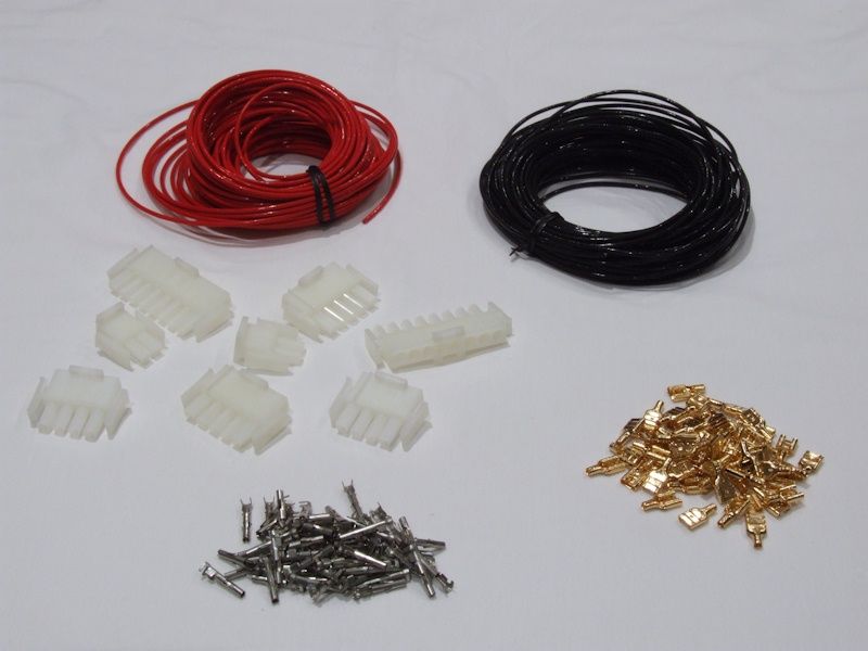
Figure 1. Main ingredients: wire and connectors.
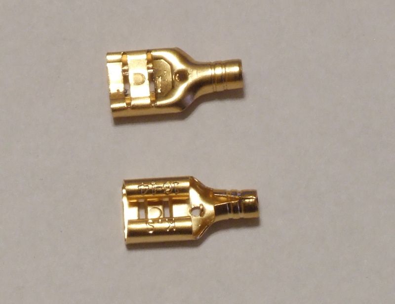
Figure2. 1/4" WBT quick disconnects, which are gold plated copper.
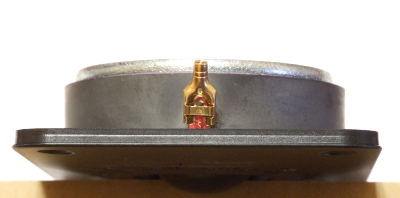
Figure 3. I found that I could use the WBT disconnects with the narrow tab on the RD0198 tweeters if I
gently pried up the middle band on the back of the disconnect and insert the tweeter tab under it.
Cardas wire has each individual strand coated with a clear polyurethane varnish. I tried two different Dremel attachments to remove the varnish:
428-Carbon Steel Brush - "Remove dirt, rust, and corrosion from most surfaces. Clean electrical connectors and other metal parts, remove buildup from faucets, clean camp stove burners and more."
530-Stainless Steel Brush - "Use on stainless steel, pewter, aluminum, silver and other white metals. Use for cleaning, deburring and surface finishing."
The carbon steel brush worked faster and better.
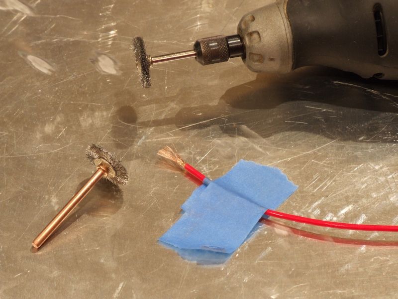
Figure 4. The carbon steel brush is attached to the Dremel. The stainless steel brush is at the lower left.
The work surface is the bottom of an aluminum baking pan.
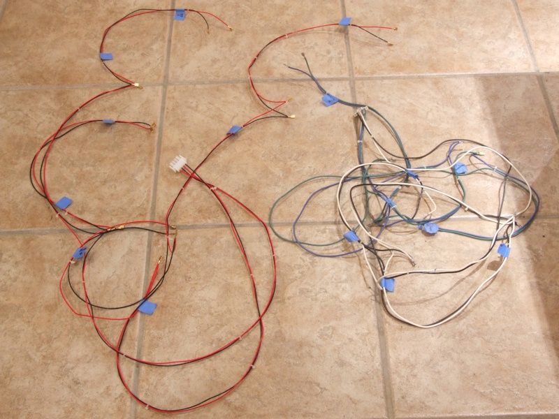
Figure 5. Driver wiring harnesses - Cardas on left, original on right.
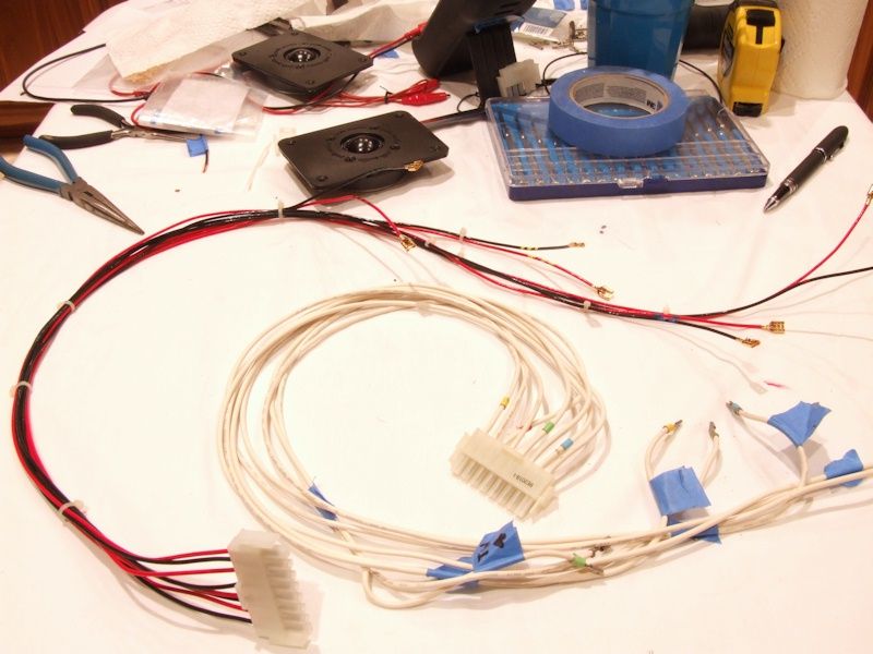
Figure 6. Tweeter wiring harness.
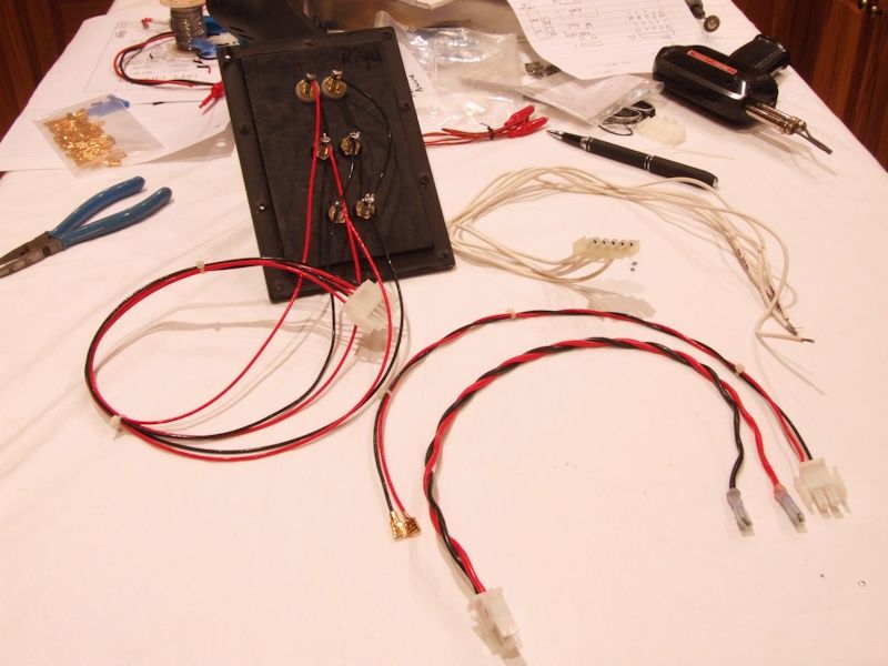
Figure 7. Binding post and SDA inductor wiring harness.
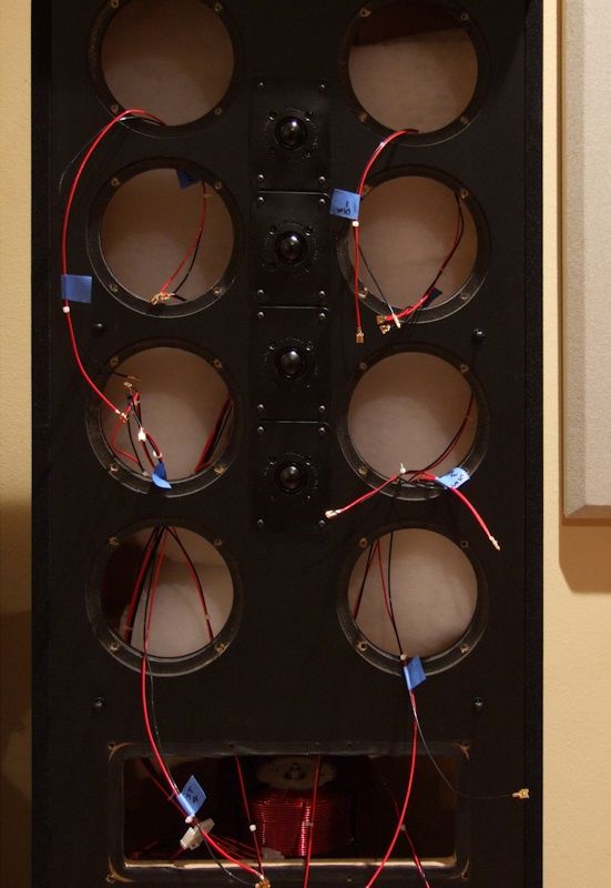
Figure 8. Cardas wire installed in the right 1.2TL.
Grinding off the clear, invisible insulation from each end of a piece of wire was a very tedious process. Added to that was the need to test for continuity with a multimeter after grinding.
Cable Conditioning
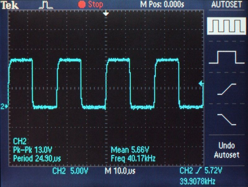
Figure 9. Cable Cooker output signal.
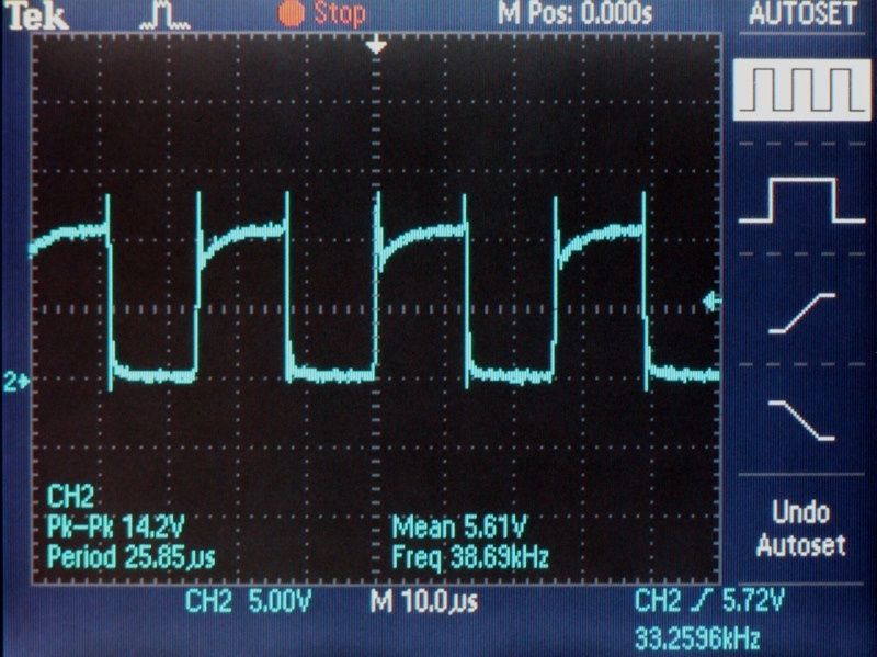
Figure 10. Cable Cooker output signal from original internal wiring.
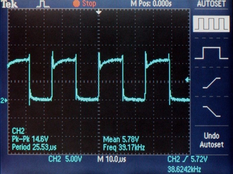
Figure 11. Cable Cooker output signal from Cardas wire after four days of conditioning.
The conditioned Cardas wire showed less ringing than the original wire.
Listening Evaluation
The right speaker was done first. However, since the results were not favorable, Cardas wire was not installed in the left speaker. With Cardas wire in the right speaker the following sonic results were obtained:
Stereo mode:
1. The sound stage on the right contracted 4 feet.
2. The right side sound level was apparently lower.
3. Less tactile sensation on the right side.
4. Less image weight on the right side.
Mono mode:
5. Less bass definition on the right.
6. Less overall detail on the right.
7. Less tactile sensation on the right.
I was expecting the Cardas wire to either sound better or the same as the original wire, not worse. I don't mean to discourage anyone from using this wire as many people, even members of this forum, have achieved good to excellent results with it. It just didn't work for me in this particular application.
I decided to take a cue from Roger Russell and rewire my SDA SRS 1.2TL's with Cardas copper Litz wire in 15.5 gauge. The Cardas wire is slightly larger than the stock wire, which is 16 gauge. This Cardas wire is the same wire that Mr. Russell uses in his $18,000 IDS-25 loudspeaker system. However, Mr. Russell does not believe the Cardas wire offers any sonic advantage over ordinary wire. He just uses it for marketing reasons. [Link: Cardas wire and the IDS-25]
There is nothing wrong with the stock wire. I just wanted to see if the better wire would make a difference in this application. The Cardas wire is a lower noise design due to the Litz configuration (reduction of strand interaction by insulating individual wire strands) and due to the polished surface of the conductors. AudioQuest uses similar technologies in their cables.
The wire was conditioned for four days (96 hours) on the Audiodharma Cable Cooker prior to assembly.
The Cardas wire measured better with respect to conducted noise, but actually sounded much worse than the original wire.
Assembly Notes
Figure 1. Main ingredients: wire and connectors.
Figure2. 1/4" WBT quick disconnects, which are gold plated copper.
Figure 3. I found that I could use the WBT disconnects with the narrow tab on the RD0198 tweeters if I
gently pried up the middle band on the back of the disconnect and insert the tweeter tab under it.
Cardas wire has each individual strand coated with a clear polyurethane varnish. I tried two different Dremel attachments to remove the varnish:
428-Carbon Steel Brush - "Remove dirt, rust, and corrosion from most surfaces. Clean electrical connectors and other metal parts, remove buildup from faucets, clean camp stove burners and more."
530-Stainless Steel Brush - "Use on stainless steel, pewter, aluminum, silver and other white metals. Use for cleaning, deburring and surface finishing."
The carbon steel brush worked faster and better.
Figure 4. The carbon steel brush is attached to the Dremel. The stainless steel brush is at the lower left.
The work surface is the bottom of an aluminum baking pan.
Figure 5. Driver wiring harnesses - Cardas on left, original on right.
Figure 6. Tweeter wiring harness.
Figure 7. Binding post and SDA inductor wiring harness.
Figure 8. Cardas wire installed in the right 1.2TL.
Grinding off the clear, invisible insulation from each end of a piece of wire was a very tedious process. Added to that was the need to test for continuity with a multimeter after grinding.
Cable Conditioning
Figure 9. Cable Cooker output signal.
Figure 10. Cable Cooker output signal from original internal wiring.
Figure 11. Cable Cooker output signal from Cardas wire after four days of conditioning.
The conditioned Cardas wire showed less ringing than the original wire.
Listening Evaluation
The right speaker was done first. However, since the results were not favorable, Cardas wire was not installed in the left speaker. With Cardas wire in the right speaker the following sonic results were obtained:
Stereo mode:
1. The sound stage on the right contracted 4 feet.
2. The right side sound level was apparently lower.
3. Less tactile sensation on the right side.
4. Less image weight on the right side.
Mono mode:
5. Less bass definition on the right.
6. Less overall detail on the right.
7. Less tactile sensation on the right.
I was expecting the Cardas wire to either sound better or the same as the original wire, not worse. I don't mean to discourage anyone from using this wire as many people, even members of this forum, have achieved good to excellent results with it. It just didn't work for me in this particular application.
Proud and loyal citizen of the Digital Domain and Solid State Country!
Post edited by DarqueKnight on
Comments
-
Well, at least it shows wire does make a difference, and it has to play well with the external speaker wire, and the internal components. Maybe 12 gauge would be better.
 Lumin X1 file player, Westminster Labs interconnect cable
Sony XA-5400ES SACD; Pass XP-22 pre; X600.5 amps
Magico S5 MKII Mcast Rose speakers; SPOD spikes
Shunyata Triton v3/Typhon QR on source, Denali 2000 (2) on amps
Shunyata Sigma XLR analog ICs, Sigma speaker cables
Shunyata Sigma HC (2), Sigma Analog, Sigma Digital, Z Anaconda (3) power cables
Mapleshade Samson V.3 four shelf solid maple rack, Micropoint brass footers
Three 20 amp circuits. -
I am highly suprised Raife. I was expecting good results. As I have said, I used it one spot in my DAC. However, it was not for the analog output signal, but for the digital input selection knob only (which worked well). I used VH Audio Pulsar Ag for the actual digital signal input. I am glad I used VH Audio wire for the analog output if this didn't yield improved results here. Thanks for your results Raife.

Taken from a recent Audioholics reply regarding "Club Polk" and Polk speakers:
"I'm yet to hear a Polk speaker that merits more than a sentence and 60 seconds discussion."
My response is: If you need 60 seconds to respond in one sentence, you probably should't be evaluating Polk speakers.....
"Green leaves reveal the heart spoken Khatru"- Jon Anderson
"Have A Little Faith! And Everything You'll Face, Will Jump From Out Right On Into Place! Yeah! Take A Little Time! And Everything You'll Find, Will Move From Gloom Right On Into Shine!"- Arthur Lee -
Thank you for posting this Raife. The results are indeed surprising as one would expect the Cardas to be audibly better than the stock tinned copper wire.
I wonder what other wire/geometries folks had good results with?"Science is suppose to explain observations not dismiss them as impossible" - Norm on AA; 2.3TL's w/sonicaps/mills/jantzen inductors, Gimpod's boards, Lg Solen SDA inductors, RD-0198's, MW's dynamatted, Armaflex speaker gaskets, H-nuts, brass spikes, Cardas CCGR BP's, upgraded IC Cable, Black Hole Damping Sheet strips, interior of cabinets sealed with Loctite Power Grab, AI-1 interface with 1000VA A-L transformer -
You should try Audioquest perfect surface wire. I find they do a much better job dollar for Dollar then Cardas does. We carry both and I much Prefer Audioquest.
They do however make really good quality cables , I never heard a standard 14 or 12 g wire sound better then a cardas of the same gauge.
Now I have to do a full head to head Cardas / Audioquest shootout IC's , speaker wire etc. I have done some IC's of a very unfair compare and kinda felt the Audioquest was as good if not better then the much higher costing Cardas cables.
Looks like a very fun and would have been rewarding project . Sorry dude it didn't come out in your favor.Dan
My personal quest is to save to world of bad audio, one thread at a time. -
Just shows to go ya, not all mods are zingers. Regardless, I think everyone truly appreciates the time and effort Ray puts into projects. Thank you for another informative article!
stubbySRS 3.1TL
Harman Kardon Citation 5.1
Anthem AVM2 -
You should try Audioquest perfect surface wire.
I did discuss this project with Alasdair Patrick at AudioQuest and he suggested their GO-4 speaker wire. GO-4 is Litz configuration perfect surface copper wire in 15 AWG and costs $15 per dual conductor foot. Go-4 is AQ's lowest priced perfect surface copper wire. Each 1.2TL requires 38 dual conductor feet, so 38 x 2 x $15 = $1140. The same amount of Cardas 15.5 AWG wire costs $266 (regular price at $3.50 per dual conductor foot). I bought my Cardas wire from Sonic Craft during a 20% off sale, so my cost was $212.80.
Understandably, I am reluctant to spend over $1K on something which may or may not work and which I can't return. In the future, when I am more dedicated to audio than I am now, I might order a small amount of the GO-4 and just wire the tweeters and or the binding post connections to see if I hear an improvement. If that works out, I might go ahead and replace all the wire.Proud and loyal citizen of the Digital Domain and Solid State Country! -
Raife, I rewired one of my 2.3tls with DH Labs S.S. wire. I had enough left over from "Gunning" my Maggie 2.7"s. The main difference on mine was the elimination of all connectors, All terminations are solder. At first I thought it was missing something but after several weeks it became obvious everything was just better focused and "faster". Several others also commented on the "faster" description without any input from me. The downside is I'm dreading pulling the left one apart to do Larry's rings! I wanted to get matching wire from Discovery to keep everything identical but they never got back with me. Hope you find wire you can appreciate that is actually an improvement.
-
DarqueKnight wrote: »In the future, when I am more dedicated to audio than I am now
Hey Raife.... is that statement above even possible? Cause I dont think so :biggrin: :razz:"....not everything that can be counted counts, and not everything that counts can be counted." William Bruce Cameron, Informal Sociology: A Casual Introduction to Sociological Thinking (1963) -
EndersShadow wrote: »Hey Raife.... is that statement above even possible? Cause I dont think so :biggrin: :razz:
He ALWAYS says that! I agree Dan! I'd like to see the AQ suggestion from mantis tried out, I wonder if more burn-in time may change it, I understand 96 hours is a long time but I'd like to hear results after 200 hours of burn in. It seems a lot of manufactures recommend 200 hours on their equipment. On a second thought, this seems a little light of a thread from DK, I think there is more to come. :biggrin: -
He ALWAYS says that! I agree Dan! I'd like to see the AQ suggestion from mantis tried out, I wonder if more burn-in time may change it, I understand 96 hours is a long time but I'd like to hear results after 200 hours of burn in. It seems a lot of manufactures recommend 200 hours on their equipment.
The Cable Cooker accelerates cable break in with a high-power, wide-bandwidth conditioning signal. The rule of thumb is 1 hour on the Cooker is roughly equivalent to 3 hours of music play. Recommended cooking times for interconnects is 36 to 60 hours and 48 to 84 hours for speaker cables. I went 96 hours (4 days) with the Cardas chassis wire because I wanted to be sure of adequate cooking time. In this case, it was impractical to follow my usual regimen of listening-cooking-listening because that would have required multiple tedious iterations of removing and reinstalling the drivers, tweeters, crossovers and binding post plates. The 96 hours of cooking time is roughly equal to 288 hours of music play time.
Figures 12-15 illustrate the changes in signal quality after cooking. A Tektronix TDS 2012 oscilloscope was used to take the time domain measurements in figures 12-15 and the frequency domain measurements (Fast Fourier Transform) in figures 16-19. It is easier to see differences in figures 14 and 15, figures 16 and 17 and figures 18 and 19 if they are saved and viewed in succession.
Figure 12. Cable Cooker output signal.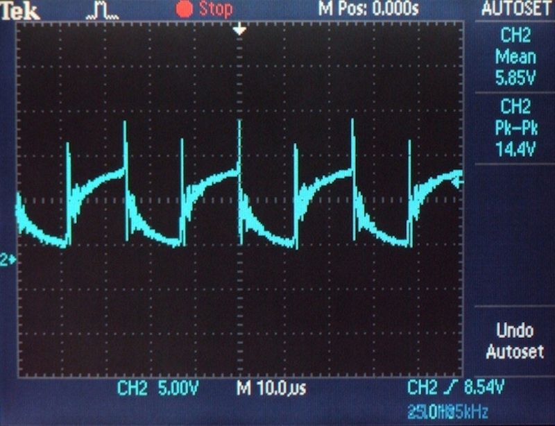
Figure 13. Cable Cooker output signal from Cardas chassis wire at the beginning of cooking.
Cardas chassis wire uses Teflon insulation which is a harsh sounding dielectric, until the molecules become polarized and saturated with energy.
Figure 14. The Cardas wire's ringing and distortion were significantly reduced after 24 hours of cooking. I did
not see any further improvements in the waveform after an additional three days of cooking. This plot is at the
96 hour point.
Figure 15. Cable Cooker output signal from the original SDA SRS 1.2TL internal wiring.
Comparing figures 14 and 15, the Cardas wire shows considerably less ringing on the falling edge of the conditioning signal pulses.On a second thought, this seems a little light of a thread from DK, I think there is more to come.
Yes, I have a little more to say.
While reviewing the Fast Fourier Transform plots, i realized that the Cardas wire showed lower noise with the 1000 Hz test signal than with the 100 Hz test signal. Another listening evaluation was done with the original tweeter wiring harness replaced with the Cardas wiring harness. Again, it is easier to see differences in figures 16 and 17 and figures 18 and 19 if they are saved and viewed in succession.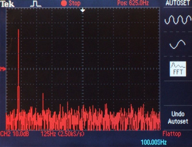
Figure 16. FFT plot of 100 Hz test signal from original internal wire.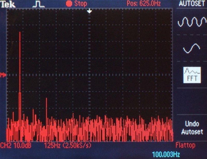
Figure 17. FFT plot of 100 Hz test signal from Cardas internal wire.
The Cardas wire demonstrated greater noise density and higher amplitude harmonics about 100 Hz than the original wire. The Cardas wire major noise amplitudes were +6 dB at the 50 Hz sub-harmonic, +3.5 dB at the 200 Hz second harmonic and +1 dB at the 300 Hz third harmonic.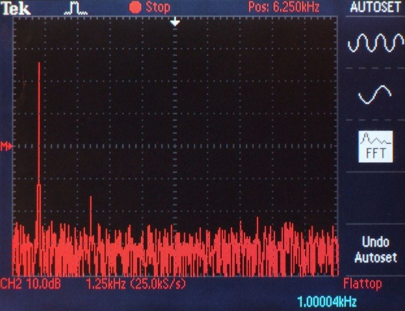
Figure 18. FFT plot of 1000 Hz test signal from original internal wire.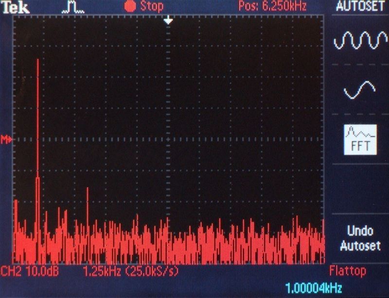
Figure 19. FFT plot of 1000 Hz test signal from Cardas internal wire.
The Cardas wire demonstrated much lower noise density and about 1000Hz, and much lower noise density overall, than the original wire. The Cardas wire major noise amplitudes were -0.5 dB at the 200 Hz second harmonic and exactly the same as the original wire at the 300 Hz third harmonic.
Listening Evaluation
With only the tweeter wiring harness replaced with Cardas wire in the right speaker, improvements similar to the "TL" modification for the SDA CRS+ and SDA 2B models were realized (4.1TL Modification-SDACRS+). The improvements were more discernable in stereo mode than in mono mode.
Mono mode with right speaker tweeter wires changed to Cardas:
1. Slight improvement in sustain and decay in stringed instruments (violins, guitar, bass, piano) and percussion instruments (shakers and cymbals) on the right.
2. The right speaker sounded louder.
3. More bass definition on the right.
4. More tactile sensation on the right.
Stereo mode with right speaker tweeter wires changed to Cardas
1. Moderate improvement in sustain and decay in stringed instruments (violins, guitar, bass, piano) and percussion instruments (shakers and cymbals) on the right.
2. More image weight on the right.
3. More bass definition and articulation on the right.
4. More tactile sensation on the right.
Since the right speaker delivered Such Good Sound with the Cardas wire in the tweeter section, I enthusiastically made a Cardas wiring harness for the left speaker.
Stereo mode with both speaker's tweeter wires changed to Cardas:
There were no changes in sound stage dimensions. There was an improvement in the sense of space between sound images (particularly front to back) and significant improvement in detail and clarity of sound images at the sides and rear of the sound stage. The sound stage was more holographic and three-dimensional. In addition to the improvments listed above, with both speaker's tweeter wires replaced, I realized:
1. More overall holography.
2. More detail in the sounds of ambient room reflections in the recording.
Assembly Addendum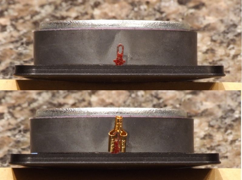
Figure 20. The topside of the WBT 1/4" quick disconnect will fit the RD0198 tweeter's narrow tab.
Figure 3 in post #1 shows how the bottom of the WBT 1/4" quick disconnect was adapted to fit the narrow positive tab of the RD0198 tweeter. It turns out that the little extensions at the bottom of the narrow tab are just the right size to fit into the front of the disconnect. I found that the disconnect's topside curved pressure plates needed to be gently bent downward with pliers for a snug fit on the positive and negative tabs of the tweeters and drivers.
Conclusion
The initial trial with the right speaker re-wired with Cardas chassis wire produced disappointing results with an overall loss of detail and detriments to spatial properties. A review of measurement data indicated that the Cardas wire might be better suited for the high frequency section alone. This was verified in listening evaluations. Prior experiments in changing internal speaker wiring provided no audible difference. In this case the results were mixed: detrimental results with a complete replacement using Cardas wire and beneficial results when Cardas wire was only used in the high frequency section.
The Cardas wire was difficult to work with due to the tedium of grinding off the polyurethane insulation, but this would not deter me from using it again in another project.
This experiment was precipitated by the good results achieved from switching to higher quality AudioQuest binding post jumpers (AQ Binding Post Jumpers). Now, I find that I must give some serious consideration to trying a higher quality Litz wire, such as AudioQuest's GO-4. I expect that the G0-4 will be much easier to work with as it is constructed of four Teflon insulated conductors that can be easily striped (2 x 17 AWG + 2 x 20 AWG for an effective AWG of 15).Proud and loyal citizen of the Digital Domain and Solid State Country! -
Raife, how much wire was required for each tweeter connection per speaker? (8 X ? in.)
Thanks for the further input.
Taken from a recent Audioholics reply regarding "Club Polk" and Polk speakers:
"I'm yet to hear a Polk speaker that merits more than a sentence and 60 seconds discussion."
My response is: If you need 60 seconds to respond in one sentence, you probably should't be evaluating Polk speakers.....
"Green leaves reveal the heart spoken Khatru"- Jon Anderson
"Have A Little Faith! And Everything You'll Face, Will Jump From Out Right On Into Place! Yeah! Take A Little Time! And Everything You'll Find, Will Move From Gloom Right On Into Shine!"- Arthur Lee -
39" for tweeter 1 (top)
35" for tweeter 2
31" for tweeter 3
27" for tweeter 4
This equated to 11 feet of black Cardas wire and 11 feet of red Cardas wire for the tweeters per speaker.Proud and loyal citizen of the Digital Domain and Solid State Country! -
Replacing the original tweeter wiring harnesses with Cardas wire harnesses resulted in sonic improvements, so I decided to revisit the Cardas wiring harnesses for the SDA inductor and the binding post plate. The Cardas binding post harness was reinstalled in the right speaker and compared to the left in mono and stereo.
1. There was a modest further improvement in bass weight, bass articulation and bass detail.
2. The right side sounded slightly louder.
3. Subtle background percussion sounds and background vocals had more detail
Reinstalling the Cardas wiring harness for the SDA inductor resulted in a further enhancement of depth. Depending on the recording, some sound images moved forward 1 foot in the center and at the sides.
The bad sound I experienced earlier has been isolated to the wiring harness for the stereo and dimensional drivers. I suspect that the length of the wires and the capacitive properties of the wire may be contributing factors. The SDA inductor harness wires and the binding post harness wires were each 24 inches long. The tweeter harness wires were
39" for tweeter 1 (top),
35" for tweeter 2,
31" for tweeter 3,
27" for tweeter 4.
The wires for the driver wiring harness comprise 19 feet 5 inches of wire (115" for positive leads and 118" for negative leads) for the stereo drivers and 19 feet 5 inches of wire (118" for positive leads and 118" for negative leads) for the dimensional drivers. This is a total of 38 feet 10 inches of wire per speaker for the drivers.
I have sent an email to Cardas, along with a wiring diagram showing the lengths of each wire segment, asking if the length of the wire is an issue in this application.
I had some concern that I might not like the Cardas wire because some reviews said it sounds "warm" and "laid back" and I like neutral. The Cardas wire does not sound warm or laid back to me. It just sounds more detailed and clear than the original wire.Proud and loyal citizen of the Digital Domain and Solid State Country! -
Just when I thought my 4.1TL's were finished.....
 Good music, a good source, and good power can make SDA's sing. Tubes make them dance.
 -
Just when I thought my 4.1TL's were finished.....
It's like trying to retire from the mafia.Can I buy your original wires?
I have a set of 1.2tl's I need to re-wire but I'm too busy to get to them.
No. I like to keep the original parts. Imagine the fun I'll have demonstrating how internal speaker wire can make an audible difference.Proud and loyal citizen of the Digital Domain and Solid State Country! -
DarqueKnight wrote: »It's like trying to retire from the mafia.
I gave up thinking I'm finished, even though I've done all the mods except using Gimpod's boards (which I have), replacing the small inductors and replacing the internal wiring.
My SDA's sound so good now it's hard to believe I could get further improvement, but you gotta test your assumptions! :cool:"Science is suppose to explain observations not dismiss them as impossible" - Norm on AA; 2.3TL's w/sonicaps/mills/jantzen inductors, Gimpod's boards, Lg Solen SDA inductors, RD-0198's, MW's dynamatted, Armaflex speaker gaskets, H-nuts, brass spikes, Cardas CCGR BP's, upgraded IC Cable, Black Hole Damping Sheet strips, interior of cabinets sealed with Loctite Power Grab, AI-1 interface with 1000VA A-L transformer -
You may want to reuse an AMP pin/socket housing and need to remove the contacts. The pin and socket contacts snap in place with two opposing metal flaps. AMP sells a $57 contact removal tool, but I was able to find a 10 cent option: using a modified socket contact.
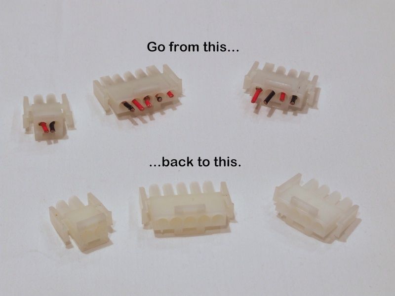
Figure 1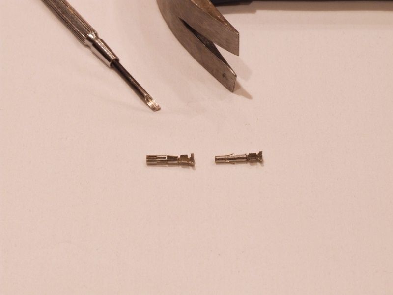
Figure 2. AMP socket contact pried open on left, regular socket contact on right.
I took a socket contact, stood it on its rear end and gently tapped a small screwdriver down the seam. The goal is to open it just wide enough so that it fits in the space between the socket to be removed and the housing. It may take some trial and error expanding the socket and then closing it down a bit with pliers.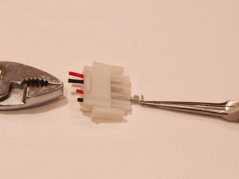
Figure 3. Push removal socket all the way in.
The AMP nylon housings are translucent, so you can see the retaining flaps and properly position the removal socket to cover them. If your housing is solid colored, like the stock SDA housings, you will have to use trial and error until you luckily cover the flaps.
Using a small pair of needle-nosed pliers, push in the removal socket all the way to the housing. Sometimes, just pushing in the removal socket pushes out the socket or pin. Sometimes, the retaining flaps are dug into the top of the housing sleeve and I need to rotate the removal socket a 1/4 or 1/2 turn, then I can easily remove the pin or socket from the top of the housing with ordinary pliers.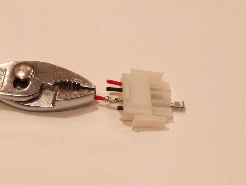
Figure 4. Pin easily pulls out once retaining flaps are held in by removal socket.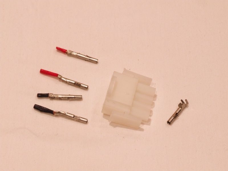
Figure 5. All done and housing is ready for reuse.Proud and loyal citizen of the Digital Domain and Solid State Country! -
Glad to hear you worked out the issue. I have a pair of Gimpod's boards sitting here, and I'm waiting for the right moment to do another round of mods.
Sure would be efficient to do the internal wiring at the same time as I populate the boards Gotta find the time though. "Science is suppose to explain observations not dismiss them as impossible" - Norm on AA; 2.3TL's w/sonicaps/mills/jantzen inductors, Gimpod's boards, Lg Solen SDA inductors, RD-0198's, MW's dynamatted, Armaflex speaker gaskets, H-nuts, brass spikes, Cardas CCGR BP's, upgraded IC Cable, Black Hole Damping Sheet strips, interior of cabinets sealed with Loctite Power Grab, AI-1 interface with 1000VA A-L transformer
 -
drumminman wrote: »I have a pair of Gimpod's boards sitting here, and I'm waiting for the right moment to do another round of mods.
Sure would be efficient to do the internal wiring at the same time as I populate the boards Gotta find the time though.
I strongly recommend doing the internal wiring some time after you have had time to assess the improvements from the crossover mod.
As nice as the Cardas wire is, I have already sent out requests for quotes on AudioQuest GO-4 speaker wire to replace the Cardas.:twisted:
The AQ wire will be much easier to work with as it only has 4 Teflon insulated conductors compared to the Cardas' 48 polyurethane insulated strands. The AQ wire just needs to be stripped and crimped compared to the Cardas wire's striping-grinding-soldering.Proud and loyal citizen of the Digital Domain and Solid State Country! -
I'm staying tuned
DK, wouldn't you be better off getting additional nylon connectors, rather than cutting the wires and re-wiring the original connector? This way it's easier to swap fully assembled wiring harnesses back and forth if you ever wanted to. Doesn't Mouser sell compatible connectors?Good music, a good source, and good power can make SDA's sing. Tubes make them dance. -
Don't suppose the AudioQuest comes in our favorite colors? Blue/Green/White/Black in particular.Good music, a good source, and good power can make SDA's sing. Tubes make them dance.
-
DarqueKnight wrote: »As nice as the Cardas wire is, I have already sent out requests for quotes on AudioQuest GO-4 speaker wire to replace the Cardas.:twisted:
So Raife it looks like your becoming more dedicated to audio again :razz:In the future, when I am more dedicated to audio than I am now, I might order a small amount of the GO-4 and just wire the tweeters and or the binding post connections to see if I hear an improvement."....not everything that can be counted counts, and not everything that counts can be counted." William Bruce Cameron, Informal Sociology: A Casual Introduction to Sociological Thinking (1963) -
I'm staying tuned
DK, wouldn't you be better off getting additional nylon connectors, rather than cutting the wires and re-wiring the original connector? This way it's easier to swap fully assembled wiring harnesses back and forth if you ever wanted to. Doesn't Mouser sell compatible connectors?
My suggestion was for cases where you no longer want to use the attached wiring configuration or, if for some reason, you need to remove the pins. For example, when assembling one of the Cardas driver wiring harnesses, I prematurely attached the pin housing and then went to put the harness on the Cable Cooker. With the AMP nylon connector on, I would have had to rig up additional wiring from the Cable Cooker terminals to the harness connector. Popping the pins out allowed me to connect the pins directly to the Cooker.
There might also be a time when someone might inserts pins in the wrong place.Don't suppose the AudioQuest comes in our favorite colors? Blue/Green/White/Black in particular.
I don't know if the bulk wire configuration for GO-4 comes in color coded jackets.EndersShadow wrote: »So Raife it looks like your becoming more dedicated to audio again :razz:
No...just curious. Proud and loyal citizen of the Digital Domain and Solid State Country! -
DarqueKnight wrote: »I strongly recommend doing the internal wiring some time after you have had time to assess the improvements from the crossover mod.
Agreed, except I've done the Xover mods (sonicaps/mills 700-1000 hours burn in) and this would only be swapping everything to the new boards. Still may confound the issue if the new boards bring about a positive change in sound as opposed to only providing more real estate for the sonicaps.
The AQ GO-4 wire will be an interesting comparison. Although teflon is a good insulator, it's typically applied thicker compared to the polyurethane on the Cardas Litz or any magnet wire. The polyurethane may come closer to the holy grail of dielectrics (air) simply because it's so thin. Also, because the wires in the Audioquest GO are much larger gauge, skin effect may cause the sound to be degraded c/w the Cardas.
Of course all this is conjecture on my part. The proof is in the pudding."Science is suppose to explain observations not dismiss them as impossible" - Norm on AA; 2.3TL's w/sonicaps/mills/jantzen inductors, Gimpod's boards, Lg Solen SDA inductors, RD-0198's, MW's dynamatted, Armaflex speaker gaskets, H-nuts, brass spikes, Cardas CCGR BP's, upgraded IC Cable, Black Hole Damping Sheet strips, interior of cabinets sealed with Loctite Power Grab, AI-1 interface with 1000VA A-L transformer -
I've got z-e-r-o experience with the AMP connectors and pins.
On the other hand, I've build a zillion GM Weatherpack wire harnesses.
Looks to me like the AMP pins are merely GM Weatherpack pins--or a close copy--that are then installed into a proprietary plastic block.
Unless I'm misled by some trick of scale, I bet an $11-or-less GM Weatherpack removal tool would work perfectly to dig the pins back out of the terminal blocks.
Close as the nearest auto parts house--NAPA, CarQuest, etc. NAPA p/n NW 725153
http://www.napaonline.com/Catalog/CatalogItemDetail.aspx?R=NW_725153_0312357064
or
http://www.amazon.com/Delphi-Packard-Weatherpack-Terminal-Release/dp/B000IIY56E
Essentially the same tool is available on eBay for ~$5 with free shipping. Search for "Weatherpack Tool"
In the same vein, one of the many styles of GM Weatherpack crimp tools would serve to make the special "W-crimp" around the bare wire that those connectors appreciate
Just to nit-pick...
The rearmost "fingers" of the pin terminal (in the GM world, anyway) are intended to grip the wire's insulation or a special silicone seal that keeps moisture (weather) out of the connector assembly. (the silicone seal would not be applicable when installing the wire into the AMP plastic connector block, I'm sure) Those rearmost fingers are not intended to grip the bare wire. Electrical contact with the wire is made with the smaller crimpable section just forward of the larger "fingers". This supports the wire better, reducing stress on the metal conductors. -
Cardas Technical Support suggested that the bad sound I was getting due only to the driver wiring harness might be due to all the polyurethane insulation not being completely ground off all the wire strands. It was suggested to solder the connects on in order to burn off any residual strand insulation. I was reluctant to do this because I wanted to avoid soldered connections.
Ok , what are they are you talking about? When you strip the conductor with lets say a 16g wire stripper , the internal conductors are left with Polyurethane Insulation left over? I don't get it? If this is true then it would be true internally of the conductor from beginning to end.
Signal travels on the outside of the conductor , we all know that , so how is it when you strip the insulation off , it's still on the end?
I ask this as I have built thousands of cables over the years and never had this issue. My other question here is these cables you purchased didn't come in a 2 conductor form? They are single conductors? Most speaker wires shield themselves with each conductor inside the Dielectric with a twisted pair design. This shields itself from EMI and RF while traveling a given distance.
From the looks of your pic's , it looks to me like you purchased single 15.5 conductors. I don't see the benefit of this unless your running single runs to things. I would use a 2 conductor pair inside a jacket of some kind even inside a speaker cabinet. I would find that to be where some benefits would be found.
Did Cardas suggest using said conductors?
I gotta re read this entire thread to get a closer handle on exactly what you are doing wrong here and now figured out what is right. Resistance is an issue of any conductor and you wouldn't want to add any unnecessary anywhere. At no point of a conductor should the Insulation not be Air floating or Non tacky. If you stip off any section of the conductor , you should get a clean copper bare conductor.Dan
My personal quest is to save to world of bad audio, one thread at a time. -
I thought using the stainless steel brush is for removing the Litz coating. From Cardas your suppose to use soldered connections to Burn off the Litz coating. I'm on the fence with this entire technology. I'd like to learn more about Cardas , we carry it and have reps that I can have long conversations about these technologies and learn more.
I terminate Cardas in the field all the time, we use Crosslink which is very nice wire. I never soldered any of my connections , I always use Pressure termination Banana or Spade connections. I have some Crosslink at the store right now I want to bring home and test the hell out of. But I'm starting to wonder if I have been doing my customers an injustice by not burning the ends. I'm gonna put in a call to our rep.Dan
My personal quest is to save to world of bad audio, one thread at a time. -
-
Ok , what are they are you talking about? When you strip the conductor with lets say a 16g wire stripper , the internal conductors are left with Polyurethane Insulation left over? I don't get it? If this is true then it would be true internally of the conductor from beginning to end.
Signal travels on the outside of the conductor , we all know that , so how is it when you strip the insulation off , it's still on the end?
The Cardas 15.5 gauge wire I used has an outer jacket of Teflon. The wire consists of 48 strands of copper. Each strand is coated with polyurethane.I ask this as I have built thousands of cables over the years and never had this issue. My other question here is these cables you purchased didn't come in a 2 conductor form? They are single conductors? Most speaker wires shield themselves with each conductor inside the Dielectric with a twisted pair design. This shields itself from EMI and RF while traveling a given distance.
From the looks of your pic's , it looks to me like you purchased single 15.5 conductors. I don't see the benefit of this unless your running single runs to things. I would use a 2 conductor pair inside a jacket of some kind even inside a speaker cabinet. I would find that to be where some benefits would be found. Did Cardas suggest using said conductors?
Cardas chassis (hookup) wire is single conductor wire which is used for electronics projects. It is not designed specifically for wiring speakers, although that is one of its recommended uses. I had to make cable pairs and bind them together with cable ties. The stock wiring uses single conductor 16 gauge wires with different colot jackets (black, white, blue, green) which are bound together into two-wire configurations with cable ties.I thought using the stainless steel brush is for removing the Litz coating. From Cardas your suppose to use soldered connections to Burn off the Litz coating. I'm on the fence with this entire technology. I'd like to learn more about Cardas , we carry it and have reps that I can have long conversations about these technologies and learn more.
I terminate Cardas in the field all the time, we use Crosslink which is very nice wire. I never soldered any of my connections , I always use Pressure termination Banana or Spade connections. I have some Crosslink at the store right now I want to bring home and test the hell out of. But I'm starting to wonder if I have been doing my customers an injustice by not burning the ends. I'm gonna put in a call to our rep.
To get ALL of the polyurethane coating off, you must use hot solder to burn it off.Proud and loyal citizen of the Digital Domain and Solid State Country! -
Unless I'm misled by some trick of scale, I bet an $11-or-less GM Weatherpack removal tool would work perfectly to dig the pins back out of the terminal blocks.
If you have one of the Weatherpack contact extration tools, would you measure the inside and outside diameter of the end? Thanks. The inside diameter of the AMP block tubes is ~4 mm. The outside diameter of the AMP socket contacts is ~2.5 mm. The inside diameter of the AMP extration tool is 2.74 mm.Just to nit-pick...The rearmost "fingers" of the pin terminal (in the GM world, anyway) are intended to grip the wire's insulation or a special silicone seal that keeps moisture (weather) out of the connector assembly.
This is true outside of GM also. Proud and loyal citizen of the Digital Domain and Solid State Country!