Improvements To Modified SDA SRS 1.2TL Crossover
Options

DarqueKnight
Posts: 6,765
Introduction
A preliminary report was posted here.
After years of being on my very long audio "to do" list, I decided it was time to give my SDA SRS 1.2TL's a proper crossover modification with an appropriately sized printed circuit board (PCB). This was first suggested to me a few years ago by forum member Madmax. In 2008, I discussed with Ken Swauger, Polk's customer service manager at that time, my interest in having a custom crossover board fabricated. However, Ken could not locate any information on the stock board's specifications or vendor, and I let the idea slip back into obscurity. More recently, forum members Gimpod and Janne discussed their good results with custom crossover circuit boards and improved custom SDA inductors.
The stock capacitors and resistors of my 1.2TL's were replaced immediately after purchase in December of 2001 with AudioCap polypropylene film capacitors and Mills MRA-12 resistors. The AudioCap capacitors were replaced with Sonicap polypropylene film capacitors in June of 2008.
This modification replaced the stock printed circuit boards and 16 mH SDA inductors.
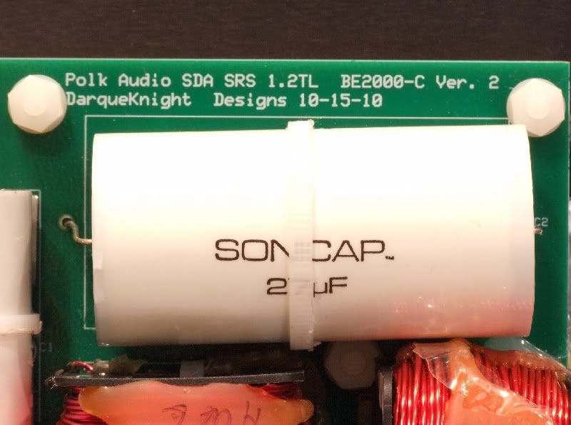
Figure 1. My big Sonicaps now have room to stretch out and breathe.
Physical Arrangement
The new PCB (printed circuit board) measures 12" long by 4.2" wide (50.4 sq. in.) with the standard thickness of 0.062". The new board is over twice the area of the original board, which measures 5-3/4" long by 4-5/16" wide (24.8 sq. in.). The populated new board main board weighs 1.8 pounds. For additional support against flexing and vibration, the main board is attached to a second board with eleven nylon standoffs. The support board rests on small sheets of Dynamat Xtreme vibration damping material. The boards were manufactured by ExpressPCB (www.expresspcb.com) using their express 4-day service. The boards were ordered on a Monday and were received the following Friday. I did the board design using Express PCB's ExpressSCH and ExpressPCB free schematic and board layout software.
The new boards are fabricated from FR-4 fiberglass epoxy with 1-1/4 ounce copper plated traces, plated through holes, silk screened top sides and solder masked under sides.
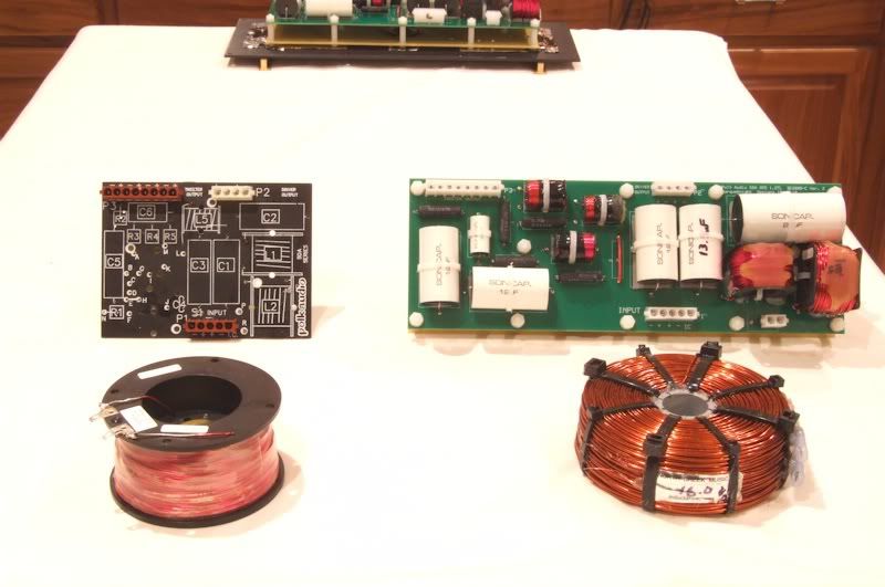
Figure 2. The original board (left) was already a very crowded configuration. Replacing the stock capacitors and resistors with larger
upgrade parts was a topological challenge. The diameter of the new custom 16 mH SDA North Creek inductor was too large (5") to fit
inside the cabinet opening (4-3/4" high) and could not be mounted flat on the crossover cover plate like the stock inductor. I asked North
Creek if they could wind the inductors to be taller with a maximum diameter of 4.5". They said their winding machines could only wind to
a maximum height of 2".
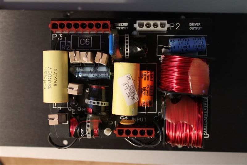
Figure 3. Stock SDA SRS 1.2TL crossover (photo by forum member Vmaxer). I was surprised to find this tiny little board inside my
1.2TL's, since the original SRS uses a large board similar in size to the new custom boards.
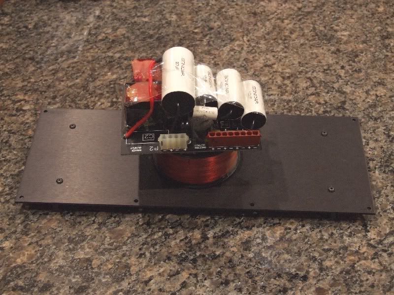
Figure 4. Modified 1.2TL crossover with piled-on Sonicap capacitors. The Mills resistors had to be mounted on the underside of the board.
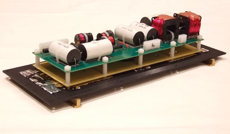
Figure 5. The original crossover had the large 16 mH SDA attached to the crossover cover plate, then the board attached to the inductor
spool with four nylon standoffs. The new inductor is mounted on a cabinet brace. The silver foil is Dynamat Xtreme vibration damping
material.
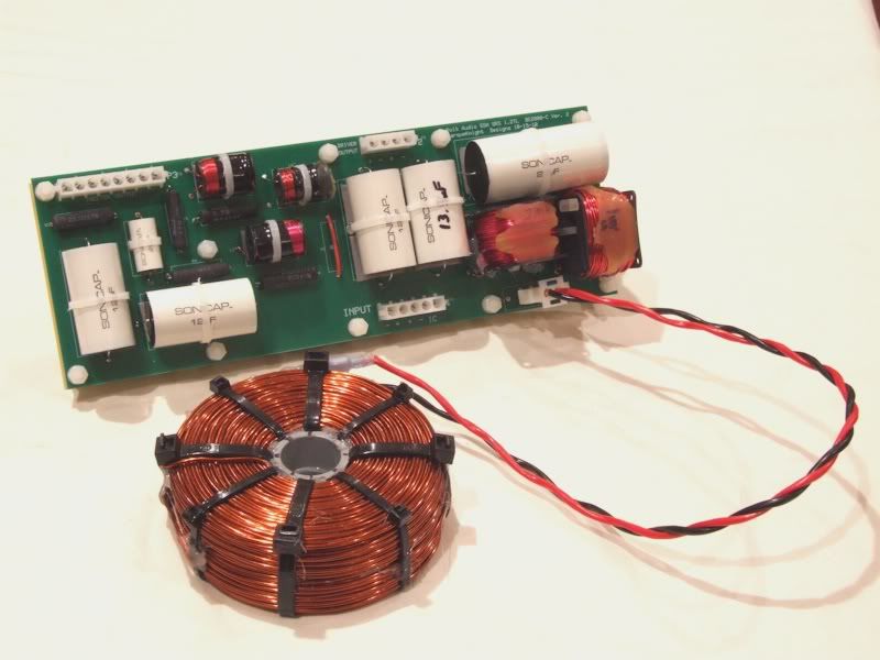
Figure 6. The wires for the new SDA inductor were first soldered to the board, just like the wires on the stock PCB. For greater removal
and installation convenience, a 2-pin header and wiring harness were installed for the inductor.
I did not think of adding a pin header for the SDA inductor until after both boards had been populated. Coincidentally, the copper traces for the SDA inductor were conveniently located so that all I needed to do to accommodate the pin header was to enlarge one of the existing holes and drill another hole 0.25" away in an adjacent trace.
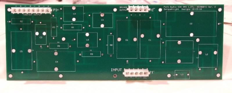
Figure 7. Silk screening on top side. This picture was taken prior to the SDA inductor wiring header being added at location L3 near the
lower right.
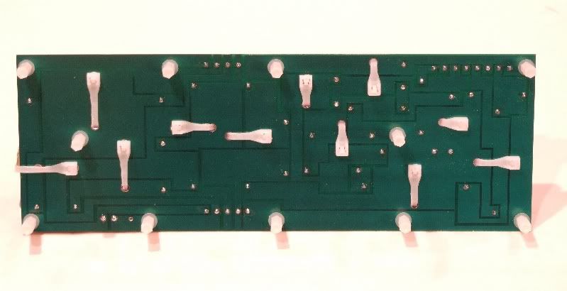
Figure 8. Solder masked copper traces on board rear.
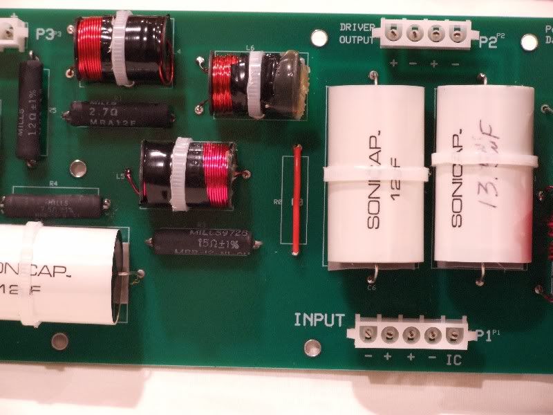
Figure 9. The red jumper is an 18 gauge solid copper wire that replaces the polyswitch.
I provided a space on the new board to replace the polyswitch with a resistor if I chose to do so. The RXE135 polyswitch has an untripped nominal DCR range of 0.12 to 0.19 ohm and a tripped DCR of 0.3 ohm. I measured the DCR's of four new RXE135 ployswitches (link). Two measured 0.16 ohm and two measured 0.17 ohm. Mills makes MRA-12 resistors in 0.1, 0.15 and 0.18 ohm. However, since removing the Polyswitches is a Polk recommended modification and since the RXE135 polyswitches have a next-to-nothing DC resistance of under 0.2 ohms, I am not in a big hurry to experiment in this area.
Mounting The SDA Inductor
The stock 16 mH SDA inductors are comprised of 18 gauge wire and have a DC resistance of 2.8 ohms. They were replaced with custom 16 mH inductors from North Creek Music Systems (14 gauge wire and 1.3 ohms DCR). Replacing the SDA inductors lowered the overall DCR of the loudspeakers from 3.8 and 3.9 ohms respectively to 3.4 ohms. My amplifiers did not seem to mind the slightly lower DCR and did not run any hotter than usual.
I experimented with three different locations for the SDA inductor: 1. A 2" wide cabinet brace running from front to back located just inside the cabinet's crossover opening. 2. The rear cabinet wall just behind, and near the top of, the passive radiator. 3. The rear cabinet wall to the side of the binding post plate.
I was surprised to find that this inductor was so sensitive to placement. Mounting the inductor behind the passive radiator (figure 12) resulted in muddy bass and diminished midrange detail. Mounting the inductor next to the binding post plate (figure 13) did not sound terrible like passive radiator location, but there was a significant loss of bass detail, articulation, and speed and some loss of midrange detail. Mounting the inductor on the narrow brace resulted in sound that was outstanding.
I sent these results to North Creek and this was the response I received:
"RE the 16mH coil, chances are it interacted with the bolt. Anything metallic anywhere near by will change its sound. It is not vibration dependent but we generally recommend mounting it to the bottom back corner so it can have adhesive on the bottom and two sides."
I used the same non-magnetic aluminum bolt, washers and nuts in each location. Perhaps the steel basket of the passive radiator had some effect. I don't know why the location near the binding post plate sounded bad. The vertical orientation might have also contributed to the sonic deterioration.
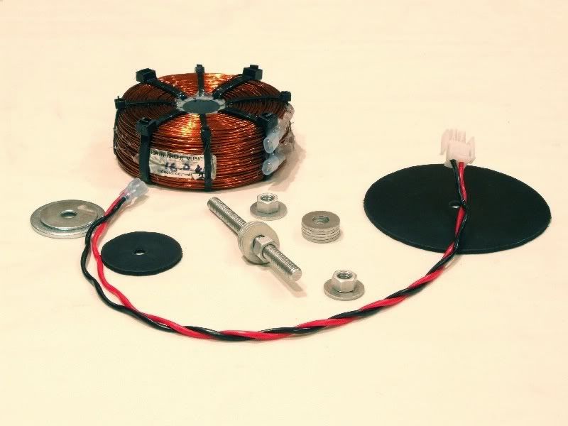
Figure 10. Toroidal inductors do not appreciate having magnetic metals inserted in their cores as this causes a rise in the amount of
inductance. The SDA inductors were attached to the cabinet brace with aluminum threaded studs, washers and hex nuts. Nylon nuts
and bolts were also tried, but were rejected in favor of sturdier metal parts.
Two inch wide aluminum fender washers for the tops of the inductors were not available locally. Steel washers were used as they only caused a little over a tenth of a mH increase in inductance, which was well within the 10% design tolerance. In contrast, a steel bolt through the center of the inductors caused a 2.5 mH increase. The 1/4" 1-1/2" steel bolt though the stock SDA inductor raised the inductance from 16.25 mH to 17 mH.
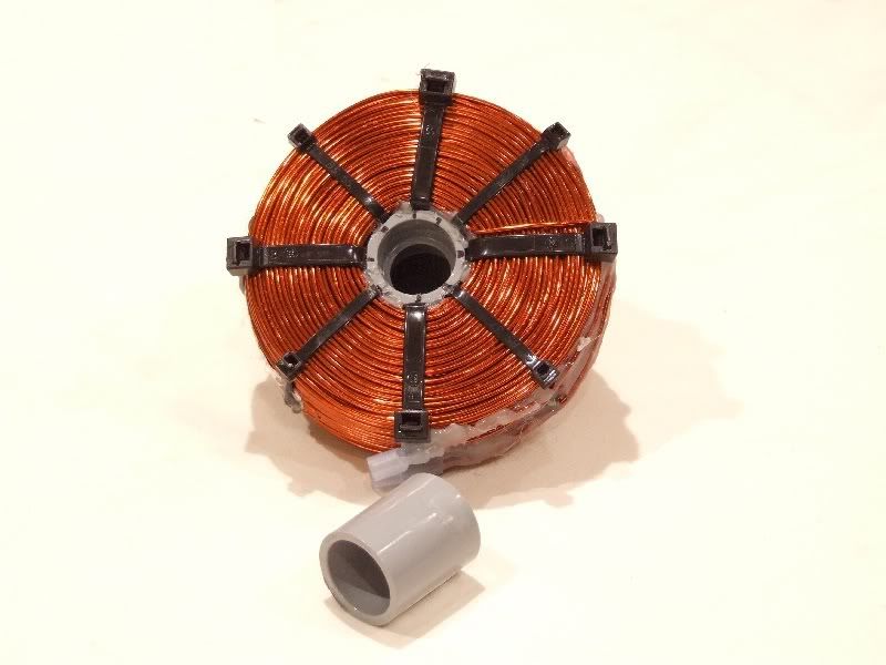
Figure 11. The inductor's mounting spool is a 3/4" plastic coupler. I found it in the plumbing department at Home Depot. It was exactly the
right length and diameter (1-9/16" long and 1-5/16" in diameter) to fit inside the inductor cores. The outside surface of the couplers had to
be ground flat in eight places to correspond to the inductor's eight binding straps.
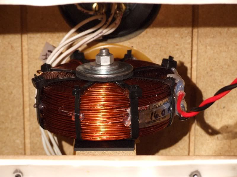
Figure 12. SDA inductor installed.
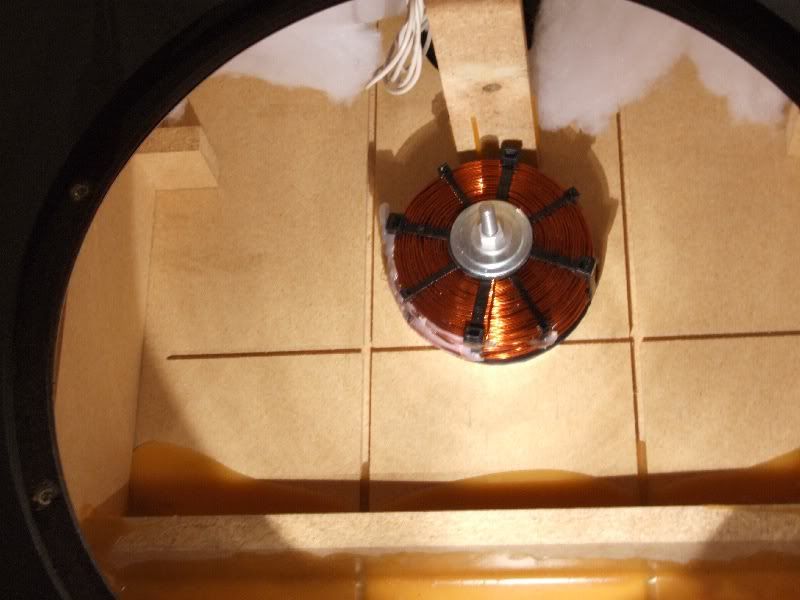
Figure 13. Nice location. Horrible sound.
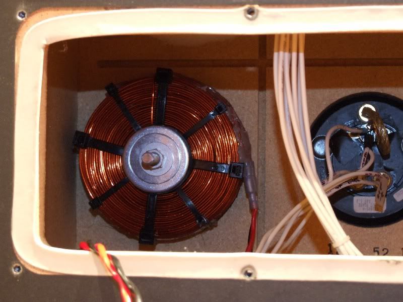
Figure 14. Nicer location, nicer sound, but nowhere near as good as the sound from the brace location.
A preliminary report was posted here.
After years of being on my very long audio "to do" list, I decided it was time to give my SDA SRS 1.2TL's a proper crossover modification with an appropriately sized printed circuit board (PCB). This was first suggested to me a few years ago by forum member Madmax. In 2008, I discussed with Ken Swauger, Polk's customer service manager at that time, my interest in having a custom crossover board fabricated. However, Ken could not locate any information on the stock board's specifications or vendor, and I let the idea slip back into obscurity. More recently, forum members Gimpod and Janne discussed their good results with custom crossover circuit boards and improved custom SDA inductors.
The stock capacitors and resistors of my 1.2TL's were replaced immediately after purchase in December of 2001 with AudioCap polypropylene film capacitors and Mills MRA-12 resistors. The AudioCap capacitors were replaced with Sonicap polypropylene film capacitors in June of 2008.
This modification replaced the stock printed circuit boards and 16 mH SDA inductors.
Figure 1. My big Sonicaps now have room to stretch out and breathe.
Physical Arrangement
The new PCB (printed circuit board) measures 12" long by 4.2" wide (50.4 sq. in.) with the standard thickness of 0.062". The new board is over twice the area of the original board, which measures 5-3/4" long by 4-5/16" wide (24.8 sq. in.). The populated new board main board weighs 1.8 pounds. For additional support against flexing and vibration, the main board is attached to a second board with eleven nylon standoffs. The support board rests on small sheets of Dynamat Xtreme vibration damping material. The boards were manufactured by ExpressPCB (www.expresspcb.com) using their express 4-day service. The boards were ordered on a Monday and were received the following Friday. I did the board design using Express PCB's ExpressSCH and ExpressPCB free schematic and board layout software.
The new boards are fabricated from FR-4 fiberglass epoxy with 1-1/4 ounce copper plated traces, plated through holes, silk screened top sides and solder masked under sides.
Figure 2. The original board (left) was already a very crowded configuration. Replacing the stock capacitors and resistors with larger
upgrade parts was a topological challenge. The diameter of the new custom 16 mH SDA North Creek inductor was too large (5") to fit
inside the cabinet opening (4-3/4" high) and could not be mounted flat on the crossover cover plate like the stock inductor. I asked North
Creek if they could wind the inductors to be taller with a maximum diameter of 4.5". They said their winding machines could only wind to
a maximum height of 2".
Figure 3. Stock SDA SRS 1.2TL crossover (photo by forum member Vmaxer). I was surprised to find this tiny little board inside my
1.2TL's, since the original SRS uses a large board similar in size to the new custom boards.
Figure 4. Modified 1.2TL crossover with piled-on Sonicap capacitors. The Mills resistors had to be mounted on the underside of the board.
Figure 5. The original crossover had the large 16 mH SDA attached to the crossover cover plate, then the board attached to the inductor
spool with four nylon standoffs. The new inductor is mounted on a cabinet brace. The silver foil is Dynamat Xtreme vibration damping
material.
Figure 6. The wires for the new SDA inductor were first soldered to the board, just like the wires on the stock PCB. For greater removal
and installation convenience, a 2-pin header and wiring harness were installed for the inductor.
I did not think of adding a pin header for the SDA inductor until after both boards had been populated. Coincidentally, the copper traces for the SDA inductor were conveniently located so that all I needed to do to accommodate the pin header was to enlarge one of the existing holes and drill another hole 0.25" away in an adjacent trace.
Figure 7. Silk screening on top side. This picture was taken prior to the SDA inductor wiring header being added at location L3 near the
lower right.
Figure 8. Solder masked copper traces on board rear.
Figure 9. The red jumper is an 18 gauge solid copper wire that replaces the polyswitch.
I provided a space on the new board to replace the polyswitch with a resistor if I chose to do so. The RXE135 polyswitch has an untripped nominal DCR range of 0.12 to 0.19 ohm and a tripped DCR of 0.3 ohm. I measured the DCR's of four new RXE135 ployswitches (link). Two measured 0.16 ohm and two measured 0.17 ohm. Mills makes MRA-12 resistors in 0.1, 0.15 and 0.18 ohm. However, since removing the Polyswitches is a Polk recommended modification and since the RXE135 polyswitches have a next-to-nothing DC resistance of under 0.2 ohms, I am not in a big hurry to experiment in this area.
Mounting The SDA Inductor
The stock 16 mH SDA inductors are comprised of 18 gauge wire and have a DC resistance of 2.8 ohms. They were replaced with custom 16 mH inductors from North Creek Music Systems (14 gauge wire and 1.3 ohms DCR). Replacing the SDA inductors lowered the overall DCR of the loudspeakers from 3.8 and 3.9 ohms respectively to 3.4 ohms. My amplifiers did not seem to mind the slightly lower DCR and did not run any hotter than usual.
I experimented with three different locations for the SDA inductor: 1. A 2" wide cabinet brace running from front to back located just inside the cabinet's crossover opening. 2. The rear cabinet wall just behind, and near the top of, the passive radiator. 3. The rear cabinet wall to the side of the binding post plate.
I was surprised to find that this inductor was so sensitive to placement. Mounting the inductor behind the passive radiator (figure 12) resulted in muddy bass and diminished midrange detail. Mounting the inductor next to the binding post plate (figure 13) did not sound terrible like passive radiator location, but there was a significant loss of bass detail, articulation, and speed and some loss of midrange detail. Mounting the inductor on the narrow brace resulted in sound that was outstanding.
I sent these results to North Creek and this was the response I received:
"RE the 16mH coil, chances are it interacted with the bolt. Anything metallic anywhere near by will change its sound. It is not vibration dependent but we generally recommend mounting it to the bottom back corner so it can have adhesive on the bottom and two sides."
I used the same non-magnetic aluminum bolt, washers and nuts in each location. Perhaps the steel basket of the passive radiator had some effect. I don't know why the location near the binding post plate sounded bad. The vertical orientation might have also contributed to the sonic deterioration.
Figure 10. Toroidal inductors do not appreciate having magnetic metals inserted in their cores as this causes a rise in the amount of
inductance. The SDA inductors were attached to the cabinet brace with aluminum threaded studs, washers and hex nuts. Nylon nuts
and bolts were also tried, but were rejected in favor of sturdier metal parts.
Two inch wide aluminum fender washers for the tops of the inductors were not available locally. Steel washers were used as they only caused a little over a tenth of a mH increase in inductance, which was well within the 10% design tolerance. In contrast, a steel bolt through the center of the inductors caused a 2.5 mH increase. The 1/4" 1-1/2" steel bolt though the stock SDA inductor raised the inductance from 16.25 mH to 17 mH.
Figure 11. The inductor's mounting spool is a 3/4" plastic coupler. I found it in the plumbing department at Home Depot. It was exactly the
right length and diameter (1-9/16" long and 1-5/16" in diameter) to fit inside the inductor cores. The outside surface of the couplers had to
be ground flat in eight places to correspond to the inductor's eight binding straps.
Figure 12. SDA inductor installed.
Figure 13. Nice location. Horrible sound.
Figure 14. Nicer location, nicer sound, but nowhere near as good as the sound from the brace location.
Proud and loyal citizen of the Digital Domain and Solid State Country!
Post edited by DarqueKnight on
Comments
-
Replacement Of Other Low Frequency Inductors
The use of a high DCR SDA inductor was a design compromise to ensure compatibility with the amplifiers commonly available 20 years ago. Replacement of this inductor with one with a low DCR is a Polk recommended modification, provided your amplifier(s) can deal with the lowered impedance.
The replacement of the other inductors in the low frequency crossover section with lower DCR inductors IS NOT a Polk recommended modification as it will change the voicing of the speaker. Whether or not the change in voicing is sonically pleasing will depend on a variety of factors such as the the amount of change in DCR and listener preferences. Refer to the comments from Matthew Polk and Stu Lumsden on inductor replacement in the document attached below.
I decided to try lower DCR North Creek replacements for the 1 mH and 2 mH inductors in the low frequency section of the crossover. I knew better than to mess with the high frequency inductors unless I kept the DCR's the same or unless I committed to a circuit redesign.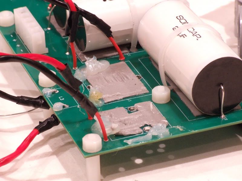
Figure 15. The stock 1 mH and 2 mH take a break after 20+ years. After the first session with the replacement inductors, I couldn't wait to
get them back in.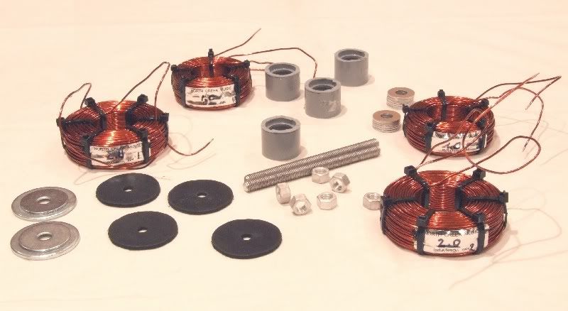
Figure 16. North Creek Music Systems 1 mH and 2 mH inductors and mounting hardware.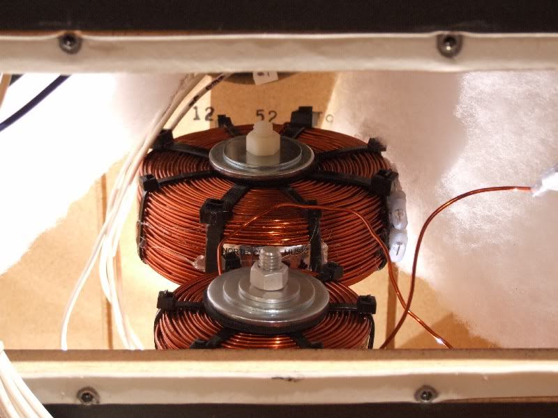
Figure 17. North Creek 2 mH (front) and 16 mH inductors.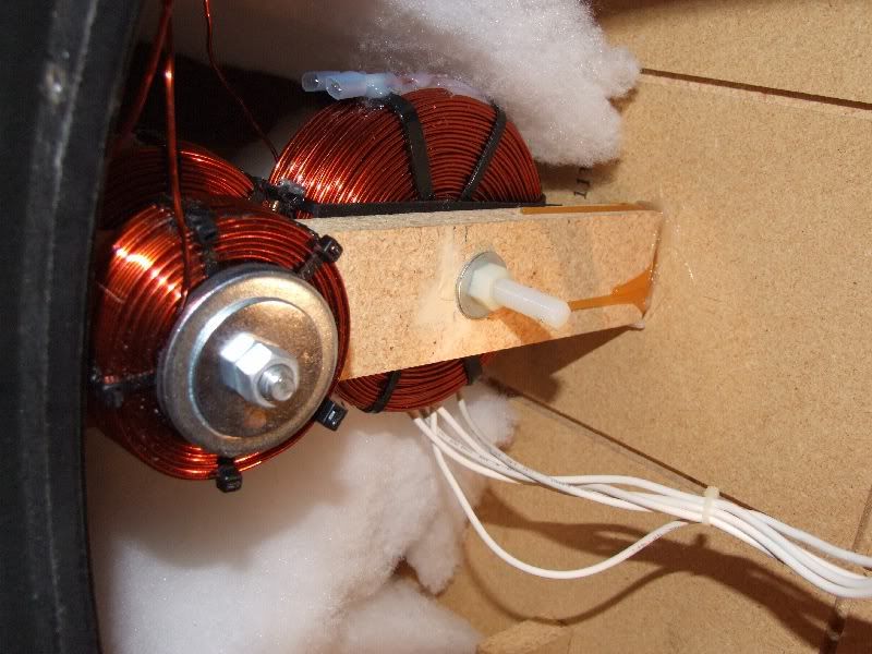
Figure 18. North Creek 1 mH inductor mounted.
The 1 mH and 2 mH replacement inductors provided sound that was harsh, disjointed (lack of coherence between low and mid/high frequencies) and the bass was muddy. I relayed these results to North Creek and I was told the inductors needed to burn in over a few days. The overall harshness went away after three days, but the other sonic aberrations remained. The 1 mH and 2 mH inductors were returned.
SDA Inductor Burn In
I was very reluctant to begin a burn in session with the Cooker because I was already enjoying Such Good Sound from the upgrade SDA inductors (and new PCB) that I didn't want to interupt my fun....but I did it anyway. It does not make sense to have wonderful conditioning devices at your disposal and not use them.
The Audiodharma Cable Cooker can be used to burn in other items besides cables. Electronic components such as resistors, inductors, transformers, capacitors and bulk wire can also be burned in on the Cooker. The Cooker's manufacturer recommended a burn in time of 4-5 days for these inductors if they were brand new, less if they had some hours on them. These inductors had 100 hours of use prior to putting them on the Cooker.
The inductors were first measured individually and then connected in series to one set of the Cooker's speaker cable outputs. The Cooker's conditioning signal was ran through the inductors in the same direction that power flows through them when they are connected to the crossover.
Oscilloscope displays were recorded at the beginning, 8th hour, 17th hour, 20th hour, 29th hour, 35th hour, 54th hour and 58th hour. Listening evaluations were done at the beginning, 17th hour and 58th hour.
As I noted in my preliminary report, I realized modest gains in bass clarity and definition, but huge gains in bass tactility. I was feeling a lot more bass rather than hearing a lot more bass. Curiously, Gimpod reported similar results with just a PCB upgrade and the stock inductor. Gimpod's results were not surprising when you consider that a circuit board is as much a circuit component as the resistors, capacitors, inductors, etc. For stereophonic audio applications, a board with larger surface area and with wider and thicker copper traces might exhibit better noise performance due to lower resistance and better power handling capability.
At the 17th hour listening session, which lasted two hours, I noted more presence and detail in high frequency percussion sounds, particularly hand claps and finger snaps and an apparently louder sound level, which was evidence of a lowered noise floor. There was a little more detail in the micro growls in the bass. The oscilloscope plots showed less ripple and ringing noise in the rising and falling edges of the conditioning signal pulses.
Since I planned to condition the inductors up to four days on the Cooker, I did not schedule another listening session until the halfway point, or 48 hours. However, some social obligations prevented a listening evaluation at the 48 hour mark. I did not have an opportunity to listen until the 58th hour. I was surprised, but pleased to find evidence of slight overcooking (blurred transients, small loss of overall detail and clarity, diminished sound stage height, diminished bass slam, loss of micro growl details in bass) at this point. I was surprised because I expected to have to cook these inductors three or more days. I was pleased because evidence of overcooking meant that I didn't have to do any more removal and reinstallation.
I did note some sonic improvements even with the overcooked inductors. The apparent sound level had increased to the point where I needed to turn the volume control down a couple of clicks. There was also an enhancement of depth at the sides of the sound stage wherein some sounds were brought almost to the sides of my seating position.
Recovery from overcooking took an unusually long time. After 5 hours of play time and 18 hours of rest, the bass was still not "correct" with regard to clarity and detail. After an additional five hours of play time, the bass clarity and detal had improved beyond the pre-cooking levels. There was also an increased sense of air and ambient information on some recordings. After five more hours of play time, I did not hear further improvement. I assumed everything was as good as it was going to get. However, the next day, after 18 hours of rest, there was more bass detail, texture, micro growls and articulation as I was hearing bass details in familiar recordings that I had not heard or documented before. The total cooking time was 58 hours followed by a recovery time of 51 hours.
Figures 20-27 show a reduction in signal deformation due to noise as the inductors were processed by the Cable Cooker. The close-up plots of the rising and falling edges of pulses are particularly interesting as they show a decrease in noise rippling with continuous processing by the Cooker.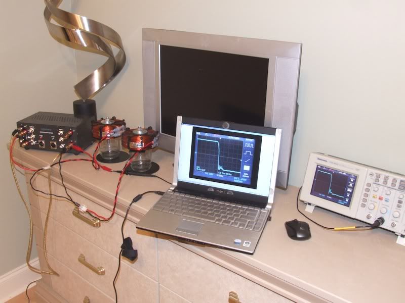
Figure 19. Left to right: Audiodharma Cable Cooker, 16 mH North Creek inductors, laptop computer for data recording and comparison,
Tektronix TDS 2010 oscilloscope.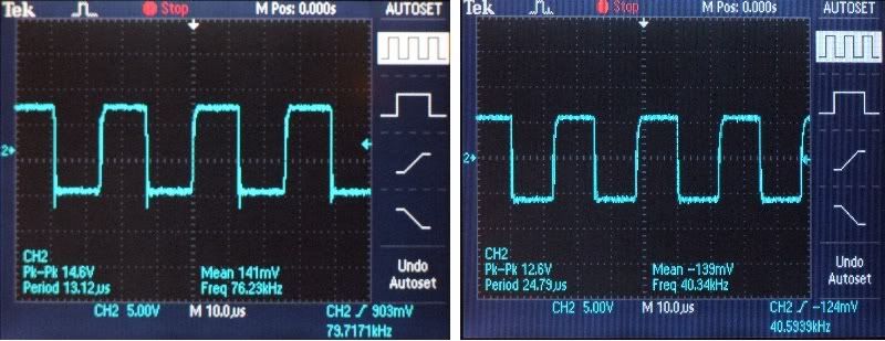
Figure 20. The Cooker's conditioning signal pulse train output from the inductors at the beginning (left) and at the 58th hour.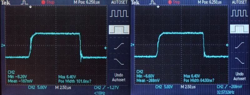
Figure 21. The Cooker's conditioning signal single pulse output from the inductors at the beginning (left) and at the 58th hour.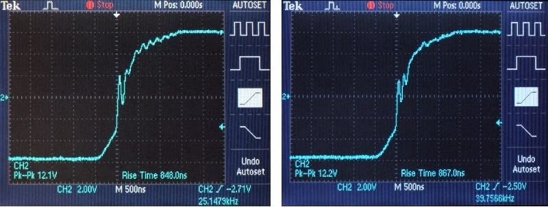
Figure 22. The Cooker's conditioning signal rising pulse output from the inductors at the 8th (left) and at the 58th hour.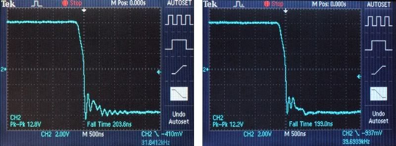
Figure 23. The Cooker's conditioning signal falling pulse output from the inductors at the 8th (left) and at the 58th hour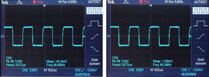
Figure 24. Input (left) and output conditioning pulses to and from the inductors at the 58th hour.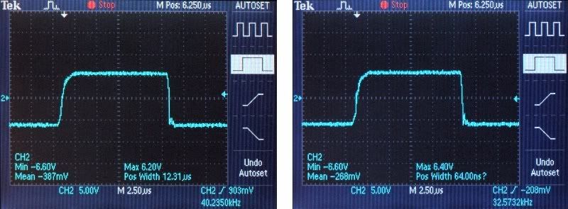
Figure 25. Closeup of input (left) and output conditioning pulse to and from the inductors at the 58th hour.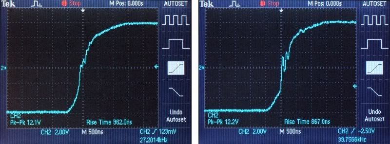
Figure 26. Closeup of input (left) and output conditioning pulse rising edge to and from the inductors at the 58th hour.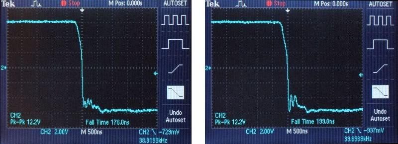
Figure 27. Closeup of input (left) and output conditioning pulse falling edge to and from the inductors at the 58th hour.Proud and loyal citizen of the Digital Domain and Solid State Country! -
Cost Break Down
This third crossover modification cost a bit more than previous mods, but I moved much further along in my quest for greater stereophonic realism and emotional thrills. Within the context of increasing and sustained aural satisfaction, it was money well spent.
1. Pair of main PCB's.................................................$268.18*
2. Pair of support PCB's.............................................$132.38*
3. Pair of 16 mH, 14 AWG North Creek inductors..........$243.47
4. Mounting hardware for PCB's and inductors..............$ 58.28
Total...............................................................................................$702.31 (A modest amount in the culture of modifications for big SDA's.)
*Boards are available from other vendors at much lower cost, but longer delivery times.
This crossover modification was more costly time wise than previous crossover mods due to the time required to learn the PCB design software and design the boards (29 hours total, 7-learning the software, 13-basic design, 9-fine tuning).
Conclusion
This was one of my more satisfying SDA modification experiences as didn't require any contortionist's skills, didn't produce any nasty surprises and it resolved a long-standing issue with board space and a serious crossover circuit design compromise. My next scheduled modification is a remodeling of the wood surfaces on my SDA SRS 1.2TL's. I have not decided if I am going to do similar modifications for the SRS's in my home theater system and my three pairs of CRS+'s.
As always, I will not be offering a board design or crossover modification service to the public. I'm saving such fun stuff until after I retire from real world employment.
References
Gimpod's SDA 1C Custom PCB Thread
Janne's 1.2TL Inductor Modification
Audiodharma Cable Cooker Review
Selected Previous SDA SRS 1.2TL Modifications
SDA SRS 1.2TL Sonicap Upgrade
Mortite Speaker Seals
SDA Steel Retaining Rings
Custom SDA Crossover Cover Plates
SDA Tweeter Brackets
Foam Rubber and Dynamat Xtreme SDA Driver Basket Insulation
AI-1 Dreadnought Isolation Transformer
Improved SDA Interconnect CablesProud and loyal citizen of the Digital Domain and Solid State Country! -
Gorgeous work.
Super impressive!design is where science and art break even. -
That's a very interesting and thorough writeup. I've read quite a few articles on x-over design, and some designers really put a lot of credence on inductor orientation, and placement. Simply having 2 inductors close together can cause quite a lot of negative interaction between them. I have a set of 2.3's and when I (soon) rebuild the crossovers, to externally mount them in a non-inductive box to keep them away from driver structure and magnets. (Also going to do that with my Carvers). This is a favorite type mod for the Maggy culture.
Thanks for the post, maybe that will help me get my butt in gear on the projects at hand!HT: Polk SDA SRS 2.3 main fronts, Klipsch RC-25 center channel, Polk RTi-150 rears, M&K V1B sub, Denon AVR-5800, Samsung 52" LCD, Sony BDP-S550
2 Channel: Carver ALS Platinum, Audio Research LS-2B preamp, Counterpoint SA-100 amplifier, Integra CD player, Denon SL7D tt, TC750 phono pre, Nikko tuner -
DK,
Curious. in the other thread you mention that the inductors cost $243.47. But here you have them at $128.60. Can you please clarify.
thanks for the review of the 1mH and 2mH inductors. Have a great day. -
DK,
Curious. in the other thread you mention that the inductors cost $243.47. But here you have them at $128.60. Can you please clarify.
thanks for the review of the 1mH and 2mH inductors. Have a great day.
Another option for coils I have been considering
http://www.partsconnexion.com/inductor_erse14.htmlHT: Polk SDA SRS 2.3 main fronts, Klipsch RC-25 center channel, Polk RTi-150 rears, M&K V1B sub, Denon AVR-5800, Samsung 52" LCD, Sony BDP-S550
2 Channel: Carver ALS Platinum, Audio Research LS-2B preamp, Counterpoint SA-100 amplifier, Integra CD player, Denon SL7D tt, TC750 phono pre, Nikko tuner -
Great writeup and details. You documented waveform changes during and after burn-in. Can you explain how burining-in, overcooking followed by resting improves the sonic performace of a coil of copper wire. Why does burning-in (almost) always result in better sound.
Thanks.'65 427 Shelby Cobra
'72 Triumph TR-6
__________________
'88 Polk SDA SRS 1.2, with upgraded XO caps and Erse SDA inductors
'86 Polk SDA CRS+
'84 Polk Monitor 10A (Peerless tweeters)
'05 HSU VTF-3 Sub (Original OEM)
'20 HSU VTF-3 Sub (three more, 100% cloned)
'93 Carver TFM-35
'88 Carver M-1.0t
'88 Adcom GFT-555
'88 Adcom GFP-555
'88 Adcom GFA-555 (upgraded/restored)
'88 Adcom GFA-555 (a second one upgraded/restored)
'05 Onkyo DV-555 media
'89 Fosgate 360 Digital Space Matrix
'89 Fosgate 360 Digital Space Matrix, internal surround amp bridged to drive only a center channel
'91 Kenwood Basic M1D Amp
'89 Pioneer Laser Disc media
'89 Sony SuperBeta HiFi media
One PGA2310 based custom built remote volume control
Four Polk T-15's
Two Polk TSi-200's
Two Polk TSi-100's
Two Polk CS-10's -
DK,
Curious. in the other thread you mention that the inductors cost $243.47. But here you have them at $128.60. Can you please clarify.
thanks for the review of the 1mH and 2mH inductors. Have a great day.
The cost was $243.47 for the pair ($114.30 each + $14.87 shipping = $243.47)
On my cost sheet, I had the cost for the pair minus shipping, $228.60, but I mistakenly wrote down $128.60 above. The total should be $702.31.
Thanks for pointing this out. I'll ask a mod to correct the error.Proud and loyal citizen of the Digital Domain and Solid State Country! -
Nice Write up as always DK!!!
Another one in my faves... -
Great writeup and details. You documented waveform changes during and after burn-in. Can you explain how burining-in, overcooking followed by resting improves the sonic performace of a coil of copper wire. Why does burning-in (almost) always result in better sound.
Thanks.
Burn in has more to do with the dielectric properties of the wire insulation than the metal wire itself. Like a capacitor, insulation can store and release energy. This absorption and release of energy can produce audible distortion. If the insulation becomes saturated with energy over a period of time, it's ability to store and release energy from/to the signal is greatly diminished.
In the case of overcooking, the insulation can become oversaturated and goes through a period of steadily releasing energy until an equilibrium state is achieved wherein the insulation is minimally storing and releasing energy.Proud and loyal citizen of the Digital Domain and Solid State Country! -
DK,
Looking at the placement of the 1mH and 2.mH inductors from your pictures I noticed you had them in the front (close to the metal of the crossover plate), right above the driver basket of the passive, and almost connected together using what looks like a metal rod. Did you experiment with moving them around at all or separating the two of them to see if that made a difference? -
I studied you plots and was wondering how they are meaninful to illustrate before/after burn-in sonic or waveform shape improvements. Your first plot for example, shows the overshoot transient present on the left plot is absent on the right. The left was plotted at 76kHz and the right at 40kHz. If you aren't comparing them at the same frequency before/after burn-in, how can you measure if anything improved? '65 427 Shelby Cobra
'72 Triumph TR-6
__________________
'88 Polk SDA SRS 1.2, with upgraded XO caps and Erse SDA inductors
'86 Polk SDA CRS+
'84 Polk Monitor 10A (Peerless tweeters)
'05 HSU VTF-3 Sub (Original OEM)
'20 HSU VTF-3 Sub (three more, 100% cloned)
'93 Carver TFM-35
'88 Carver M-1.0t
'88 Adcom GFT-555
'88 Adcom GFP-555
'88 Adcom GFA-555 (upgraded/restored)
'88 Adcom GFA-555 (a second one upgraded/restored)
'05 Onkyo DV-555 media
'89 Fosgate 360 Digital Space Matrix
'89 Fosgate 360 Digital Space Matrix, internal surround amp bridged to drive only a center channel
'91 Kenwood Basic M1D Amp
'89 Pioneer Laser Disc media
'89 Sony SuperBeta HiFi media
One PGA2310 based custom built remote volume control
Four Polk T-15's
Two Polk TSi-200's
Two Polk TSi-100's
Two Polk CS-10's -
DK, cant wait to see how the x-ocer will look for your SRS's.
also, I find the idea of making them external xovers very interesting. would there be any benefit to this? Perhaps further lessening interference?design is where science and art break even. -
I studied you plots and was wondering how they are meaninful to illustrate before/after burn-in sonic or waveform shape improvements. Your first plot for example, shows the overshoot transient present on the left plot is absent on the right. The left was plotted at 76kHz and the right at 40kHz. If you aren't comparing them at the same frequency before/after burn-in, how can you measure if anything improved?
I assure you, the left was not plotted at 76 kHz and the right at 40 kHz.
Before I go further, we must be mindful of a couple of things:
1. The Cable Cooker's conditioning signal sweeps from DC (0 Hz) to a little over 40 KHz (Reference: Cable Cooker Overview Webpage). Therefore, the 76.23 kHz frequency reading under the waveform and the 79.7171 kHz frequency sweep reading at the far lower right must be something else other than the Cable Cooker's conditioning signal.
2. The TDS 2012 is a digital sampling oscilloscope which samples at twice the frequency of the signal being measured.
Note that the vertical and horizontal scale divisions for the oscilloscope screen are at the lower center of the screen. Both the left and right plots show 5 volts per vertical division (one volt per dot) and 10 us (micro seconds) per horizontal division (2 us per dot). Therefore, both left and right plots are using the same amplitude and time scales.
If we start at in the middle of the left plot and count rightward along the major horizontal axis for one period (one upward and one downward swing), we count 13 dots or a period (T) of 26 us. This corresponds to a frequency (f) of 38.46 kHz (f=1/T). Yet, the period and frequency readings under the waveform show 13.12 us and 76.23 kHz respectively.
One of the idiosyncrasies of my trusty old TDS 2012 is that, when it is measuring a rapidly sweeping signal, such as the Cable Cooker's, and I hit the "Stop" button to freeze the display at maximum amplitude, sometimes question marks will appear in the period and frequency displays under the waveform if the oscilloscope didn't lock on the signal properly. Sometimes the oscilloscope will latch onto the sampling signal frequency and display that period and frequency instead. This was the case in the left plot of figure 20.
Do you have specific questions about the other plots?Proud and loyal citizen of the Digital Domain and Solid State Country! -
Nice write up, I have no idea of about 90% of what you were talking about
 but nice job. “The two most important days in your life are the day you are born and the day you find out why.” ~ Mark Twain
 -
DK,
Looking at the placement of the 1mH and 2.mH inductors from your pictures I noticed you had them in the front (close to the metal of the crossover plate), right above the driver basket of the passive, and almost connected together using what looks like a metal rod. Did you experiment with moving them around at all or separating the two of them to see if that made a difference?
That elegant custom crossover plate is made of non-magnetic, non-ferrous aluminum, so the inductors don't "see" it. The steel basket of the passive radiator was far enough away that the inductors couldn't "see" it. The metal rods, washers and nuts are aluminum, so the inductors do not "see" them.
I did not experiment with moving the 1 mH and 2 mH inductors around like I did with the 16 mH inductor.DK, cant wait to see how the x-ocer will look for your SRS's.
You're scaring me.
Seriously, I was thinking about this earlier today and the topological problems of placing those big Solen 130 uF capacitors. I might end up doing a two or three level board...sometime in the future...when I am more dedicated to audio than I am now.also, I find the idea of making them external xovers very interesting. would there be any benefit to this? Perhaps further lessening interference?
I gave some thought to doing this. Some speaker designs have the crossovers (1)in a separate external box, (2) in an external compartment on the rear of the cabinet or (3) in a sealed and vibration damped compartment inside the cabinet.
There certainly is some benefit to removing electronic components out of a vibration intensive environment.Proud and loyal citizen of the Digital Domain and Solid State Country! -
Finally replacing inductors....why so long in doing so?CTC BBQ Amplifier, Sonic Frontiers Line3 Pre-Amplifier and Wadia 581 SACD player. Speakers? Always changing but for now, Mission Argonauts I picked up for $50 bucks, mint.
-
when I am more dedicated to audio than I am now.
That's a scary thought. Political Correctness'.........defined
"A doctrine fostered by a delusional, illogical minority and rabidly promoted by an unscrupulous mainstream media, which holds forth the proposition that it is entirely possible to pick up a t-u-r-d by the clean end."
President of Club Polk -
Finally replacing inductors....why so long in doing so?
I have not always been interested in pushing the limits of performance in my audio gear. Modest modifications...sure. Custom boards, extensive vibration abatement and out of spec, yet higher performance parts....no. I had to gradually grow into that sort of thing.That's a scary thought.
Indeed. Proud and loyal citizen of the Digital Domain and Solid State Country! -
DarqueKnight wrote: »I have not always been interested in pushing the limits of performance in my audio gear. Modest modifications...sure. Custom boards, extensive vibration abatement and out of spec, yet higher performance parts....no. I had to gradually grow into that sort of thing.
Indeed.
I think that you've always pushed the limits DK. Just because I've done one thing different was just a question and wish you'd done it sooner. I also haven't gone to the extreme of custom PCB, aside from DIY wafers, and vibration abatement so I know what you mean from a practical sense. We had a couple new members bring a whole new effort to the nerds, of which I'm proudly a member. TFL really took the ball and ran with it in regards to the rings project. The custom PCB is not neccesary but surely a spot-on convenience for the wary folks. All of which we didn't have 5 years ago, which is super cool. What other forum has members' like this? N O N E.
You always bring something new to the table and have created a new soul to what we all love in regards to Polk Audio. We may disagree about this or that but in the end, it doesn't matter and it's only because we give a hoot about our hobby but moreso Polk.
-MarkCTC BBQ Amplifier, Sonic Frontiers Line3 Pre-Amplifier and Wadia 581 SACD player. Speakers? Always changing but for now, Mission Argonauts I picked up for $50 bucks, mint. -
DarqueKnight wrote: »I assure you, the left was not plotted at 76 kHz and the right at 40 kHz.
If we start at in the middle of the left plot and count rightward along the major horizontal axis for one period (one upward and one downward swing), we count 13 dots or a period (T) of 26 us. This corresponds to a frequency (f) of 38.46 kHz (f=1/T). Yet, the period and frequency readings under the waveform show 13.12 us and 76.23 kHz respectively.
Do you have specific questions about the other plots?
My unfamiliarity with the way your scope samples and displays vertical and horizontal scale data lead me to take what I read on the screen at face value.
Granted in Fig20, both plots were sampled at the same 38kHz frequency and post burn-in, the transient went away. How did the inductor perform pre/post burn-in within the frequency range where the SDA MW operates? How audible is that little overshoot present at 38kHz in a circuit that contains the other components of the L/C network that roll the MW output off starting at 2kHz. In other words, is testing above, let's say, 10kHz meaningful given the other componets will attenuate frequencies above the established XO point for MW.'65 427 Shelby Cobra
'72 Triumph TR-6
__________________
'88 Polk SDA SRS 1.2, with upgraded XO caps and Erse SDA inductors
'86 Polk SDA CRS+
'84 Polk Monitor 10A (Peerless tweeters)
'05 HSU VTF-3 Sub (Original OEM)
'20 HSU VTF-3 Sub (three more, 100% cloned)
'93 Carver TFM-35
'88 Carver M-1.0t
'88 Adcom GFT-555
'88 Adcom GFP-555
'88 Adcom GFA-555 (upgraded/restored)
'88 Adcom GFA-555 (a second one upgraded/restored)
'05 Onkyo DV-555 media
'89 Fosgate 360 Digital Space Matrix
'89 Fosgate 360 Digital Space Matrix, internal surround amp bridged to drive only a center channel
'91 Kenwood Basic M1D Amp
'89 Pioneer Laser Disc media
'89 Sony SuperBeta HiFi media
One PGA2310 based custom built remote volume control
Four Polk T-15's
Two Polk TSi-200's
Two Polk TSi-100's
Two Polk CS-10's -
Very nice to see one of my photos in your report....Guess that makes me eligible for a set of boards:biggrin::eek::redface:Pio Elete Pro 520
Panamax 5400-EX
Sunfire TGP 5
Micro Seiki DD-40 - Lyra-Dorian and Denon DL-160
PS Audio GCPH phono pre
Sunfire CG 200 X 5
Sunfire CG Sig 405 X 5
OPPO BDP-83 SE
SDA SRS 1.2TL Sonicaps and Mills
Ctr CS1000p
Sur - FX1000 x 4
SUB - SVS PB2-Plus
Workkout room:
Sony Bravia XBR- 32-Inch 1080p
Onkyo TX-DS898
GFA 555
Yamaha DVD-S1800BL/SACD
Ft - SDA 1C
Not being used:
RTi 38's -4
RT55i's - 2
RT25i's -2, using other 2 in shop
LSI 15's
CSi40
PSW 404 -
Very nice to see one of my photos in your report....Guess that makes me eligible for a set of boards:biggrin::eek::redface:
You are eligible. Absolutely.:biggrin:Proud and loyal citizen of the Digital Domain and Solid State Country! -
My unfamiliarity with the way your scope samples and displays vertical and horizontal scale data lead me to take what I read on the screen at face value.
OK.Granted in Fig20, both plots were sampled at the same 38kHz frequency and post burn-in, the transient went away. How did the inductor perform pre/post burn-in within the frequency range where the SDA MW operates?
No only did the transient go away, but more importantly, the overall output waveform became smoother and closer to the input waveform.
Another thing to consider is that the transient/overtone/harmonic performance of audio gear is very important. These transients add much of the "sparkle" and lifelike realism to recorded music.
I did not do any quantitative testing/measurements with audio frequency signals (20-20kHz). I did do subjective listening comparisons with the inductors pre and post burn in. The sound with the "raw" inductor was outstanding. The sound with the "cooked" inductor was spectacular.How audible is that little overshoot present at 38kHz in a circuit that contains the other components of the L/C network that roll the MW output off starting at 2kHz. In other words, is testing above, let's say, 10kHz meaningful given the other componets will attenuate frequencies above the established XO point for MW.
Sure it is...and you bring up a good point.
You might find some of the background information on the purpose and operation of the Cable Cooker helpful. It is available at the Audioexcellenceaz.com website. The purpose of the Cooker's high power, high frequency signal is to "stress" a cable above and beyond what an audio signal can do, similar to the way an athlete "over trains" for an athletic event. A runner does not train for a 5km race by running only 5km, they do substantially more than that in practice. You might very well ask, is running 10km in practice overkill if you are only going to run a 5km race?
The improved transient and noise performance at the Cooker's peak output provided some insight into how well lower power audio signals would be handled.
I could have added another step to my testing by talking waveform measurements at the outputs of the low pass filter circuit pre and post burn in, in addition to the conditioning signal measurements and listening tests. However, what I did do told me what I needed to know. Proud and loyal citizen of the Digital Domain and Solid State Country! -
DarqueKnight wrote: »
I gave some thought to doing this. Some speaker designs have the crossovers (1)in a separate external box, (2) in an external compartment on the rear of the cabinet or (3) in a sealed and vibration damped compartment inside the cabinet.
There certainly is some benefit to removing electronic components out of a vibration intensive environment.
What I would love to make would be custom external xover boxes with custom faceplates by TFL. maybe even rack-mounted!
Problem is I have no idea how I'd even begin to figure out a PCB design. so I guess I'll just have to wait for "someone" to do the heavy lifting... hehehe
:biggrin:design is where science and art break even. -
DarqueKnight wrote: »No only did the transient go away, but more importantly, the overall output waveform became smoother and closer to the input waveform.
Another thing to consider is that the transient/overtone/harmonic performance of audio gear is very important. These transients add much of the "sparkle" and lifelike realism to recorded music.
These statements define the paradox that audio reproduction presents. On one hand you strived to make the component perform smoother and closer to the input waveform. On the other hand you recognized it's the components deviation from the input waveform that adds the lifelike realism to the music.
The entire sum of all the parts in the the audio chain must complement each other to produce pleasing music reproduction, not withstanding the room acoustics and the recording component chain.
Thank you for your work to improve the SRS. I like the idea of replacing the inductor with a lower DCR value. I see some real potential value in that mod.
I've worked with about every type of analog circuit from DC to RF and I'm not convinced that burning-in caps or inductors has any real value but that's just my opinion. My experience suggests that as parts age or burn-in, they either don't deviate or they deviate away from their designed values which in most cases causes degradation in performance that must be adjusted out if possible. To my point, we pay good money for components that have close tolerances, stability, and electrical characteristics. I can't get my head around the idea we must burn them in make them drift away from their initial values in order to improve them and when they do drift, they usually drift in a way that improves them.
Please take no offense to my opinion This topic is like politics or religion. There is no absolute proof. The proof is in the hearing and that might be completely different for each of us. '65 427 Shelby Cobra
'72 Triumph TR-6
__________________
'88 Polk SDA SRS 1.2, with upgraded XO caps and Erse SDA inductors
'86 Polk SDA CRS+
'84 Polk Monitor 10A (Peerless tweeters)
'05 HSU VTF-3 Sub (Original OEM)
'20 HSU VTF-3 Sub (three more, 100% cloned)
'93 Carver TFM-35
'88 Carver M-1.0t
'88 Adcom GFT-555
'88 Adcom GFP-555
'88 Adcom GFA-555 (upgraded/restored)
'88 Adcom GFA-555 (a second one upgraded/restored)
'05 Onkyo DV-555 media
'89 Fosgate 360 Digital Space Matrix
'89 Fosgate 360 Digital Space Matrix, internal surround amp bridged to drive only a center channel
'91 Kenwood Basic M1D Amp
'89 Pioneer Laser Disc media
'89 Sony SuperBeta HiFi media
One PGA2310 based custom built remote volume control
Four Polk T-15's
Two Polk TSi-200's
Two Polk TSi-100's
Two Polk CS-10's -
DarqueKnight wrote: »No only did the transient go away, but more importantly, the overall output waveform became smoother and closer to the input waveform.
Another thing to consider is that the transient/overtone/harmonic performance of audio gear is very important. These transients add much of the "sparkle" and lifelike realism to recorded music.These statements define the paradox that audio reproduction presents. On one hand you strived to make the component perform smoother and closer to the input waveform. On the other hand you recognized it's the components deviation from the input waveform that adds the lifelike realism to the music.
You misunderstood my comment about the pre-cooking transient. The transient in the left plot of figure 20 was an added noise artifact that was not present in the input signal. Those types of transients DO NOT add realism to music and in fact. Such transients do a lot to detract from stereophonic realism.
The type of transient I was referring to in my second comment concerns transients that are part of the original recorded musical performance. Such transients can tax the ability of electronic circuits to reproduce them cleanly without added transient noise artifacts.
Burn in reduces the noise floor of a component and improves the ability to reproduce demanding parts of an audio signal. A component that does not contain a large amount of randomly stored energy will not have energy to spurriously release into an audio signalThe entire sum of all the parts in the the audio chain must complement each other to produce pleasing music reproduction, not withstanding the room acoustics and the recording component chain.
Absolutely.I can't get my head around the idea we must burn them in make them drift away from their initial values in order to improve them and when they do drift, they usually drift in a way that improves them.
Some things in audio are counterintuitive.
However, I want to reiterate that burn is not about forcing a drift from initial component values. The 16 mH inductor was still a 16 mH inductor post burn in. What changed was the inductor's ability to absorb and release energy in a way that created audible noise artifacts.Please take no offense to my opinion This topic is like politics or religion. There is no absolute proof. The proof is in the hearing and that might be completely different for each of us.
No offense taken. I appreciated your discussion. I'm sure other people reading this had some of the same questions.
I also appreciate skepticism as I am fairly skeptical myself. However, over the years I have learned to be skeptical, but go and listen anyway. Proud and loyal citizen of the Digital Domain and Solid State Country! -
Awesome Ray, absolutely superb!!!
-
DK, I am truly amazed at the depth to which you have experimented! And not just you, but many on this forum. I also appreciate the scientific approach you have used in a step-wise fashion for each upgrade. It is nice to know the audible (and/or measured) benefits of each step in the upgrade process. For a newbie like myself, it is nice to prioritize and budget upgrades based upon the blood, sweat, and tears of others. I hope to be able to someday just add 1 small amount of info that will be useful.
I have a couple of questions about upgrading the inductors on my SRS (along w/ caps and resisistors, rings by TFL, dynamat, RDO194's, mortite, interconnect and posts). First, I assume from your experience that you would recommend only upgrading the 16mH inductor in the dimensional array? Second, is the 'stock' (as opposed to your custom) crossover plate ferrous and/or magnetic?SDA SRS modded: Xovrd, de-polyed, inductorized, interconnectorized, re-posted, dynamited, RDOd, spiked, gasketed, ringed (Larry's), and grill cloth blinged! Done this on my own? Not a chance. Thanks to Raife and all who forged easy to follow upgrades. At least a 100% improvement in sound and my personal listening pleasure! :cheesygrin:Pass XP-10 preamp, Parasound A21 amp, Pioneer Elite DV-58AV (Ric Shultz modded), Audioquest Sky IC's, No longer need my Sunfire sub after mods... -
DK, I am truly amazed at the depth to which you have experimented! And not just you, but many on this forum. I also appreciate the scientific approach you have used in a step-wise fashion for each upgrade. It is nice to know the audible (and/or measured) benefits of each step in the upgrade process. For a newbie like myself, it is nice to prioritize and budget upgrades based upon the blood, sweat, and tears of others. I hope to be able to someday just add 1 small amount of info that will be useful.
Thank you. I am just doing my part to give back to a hobby and audio community that has greatly enriched my life and leisure time.First, I assume from your experience that you would recommend only upgrading the 16mH inductor in the dimensional array?
I highly recommend the upgrade to a lower DCR 16 mH SDA inductor. However, for the other inductors, you may hear some improvement with higher quality inductors, provided they have the same DCR as the stock inductors. I plan to leave my stock small inductors in place.Is the 'stock' (as opposed to your custom) crossover plate ferrous and/or magnetic?
Both the stock and the custom crossover plate are non-magnetic aluminum.Proud and loyal citizen of the Digital Domain and Solid State Country!