The AI-1 Dreadnought Project Pt.2 - Upgrade to 1000VA Transformer
Options
Comments
-
DarqueKnight wrote: »If you have the opportunity to hear properly set up LSi's and LSiM's...and other high quality speakers, I would urge you to do so for educational and reference purposes.
Still on my "To-Do" list. Unfortunately there are no speakers of those series sold locally here at this time. I've been told Certain stores in Canada will carry the LSiM line soon.
I'm lying. There is a guy selling a NIB pair of LSi15's for $1500 on the classifieds for the last 4 months. Wasn't THAT interested to hear them for that price. -
I participated in the recent group buy and purchased two additional Avel Lindberg AV-047548 1000VA isolation transformers. The size, weight and electrical measurements of the two recently received AV-047548 transformers are consistent with the first two I ordered, although the parallel inductance of unit #3 was roughly 25% less than the other three units. Unit #3 did not sound different from units #2 and #4 in listening tests.
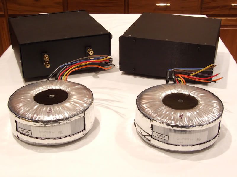
Figure 1. Avel-Lindberg AV-047548 1000VA transformers and aluminum cases.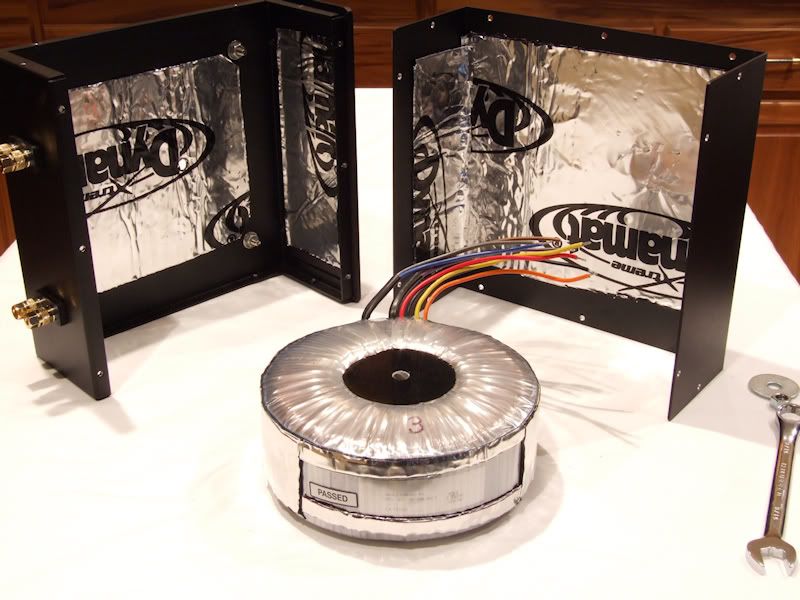
Figure 2. Per usual, the aluminum cases and the transformer perimeter were lined with Dynamat Xtreme vibration damping material.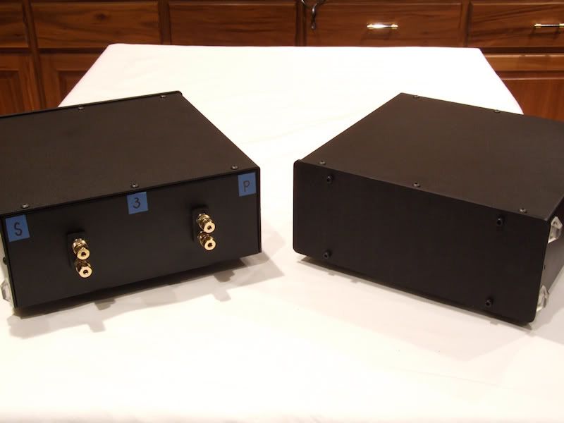
Figure 3. Finished assemblies ready for burn in and testing.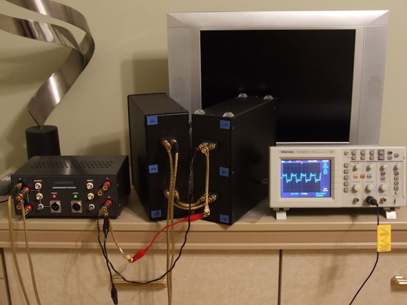
Figure 4. Cable Cooker burn in setup.
Table 1. Measurements of Four AV-047548 Transformers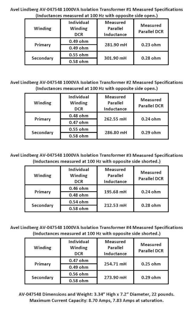
Listening Tests
Listening tests were done with a pair of modified SDA CRS+ loudspeakers and the following electronics in my home theater system:
Pioneer Elite BPD-09FD Blu-ray/CD player,
Sony TA-P9000ES preamp,
Adcom GFA-5500 power amp,
Monster Cable Z2 Reference speaker cable,
Monster Cable Z100i Interconnects,
Monster Cable Z3 Reference speaker cable Dreadnought interconnects,
PS Audio P10 AC Regenerator.
New units #3 and #4 were compared to previously purchased unit #2.
Units #3 and #4 were connected in series and burned in on the Audiodharma Cable Cooker for 24 hours.
I noted in a prior listening evaluation (post #117, page 4 of this thread) that the Dreadnought sounded better when oriented vertically, resting on a side, rather than oriented horizontally, resting on its feet. I accidentally found out that the choice of vertical orientation (resting on the left or right side) also affected the sound.
My Dreadnoughts are wired (as you face the front of the case) with the primary connections on the left and the secondary connections on the right. Four 3/4" high rubber pads are placed on the left side so that the Dreadnought rests vertically with the primary connections next to the floor.
When I assembled unit #3, I unknowingly installed the case top "backwards" so that the side rubber pads were on the right, rather than left side. This meant that the vertical orientation for unit #3 had the secondary connections next to the floor. Compared to unit #2, unit #3 had noticeably less overall clarity, detail and tactile sensation. There was also a small reduction in depth. I did not hear any other spatial property differences between unit #3 and unit #2. When I moved to unit #4, I expected it to sound like unit #3, since they were burned in simultaneously on the Cable Cooker. I thought more burn in time was needed. Surprisingly, I heard no difference between unit #2 and unit #4.
While comparing listening notes and spatial rendering charts for units #2, #3 and #4, my next thought for explaining the differences heard with unit #3 might the lower parallel inductance measured. Then, I noticed that unit #3 had the case top oriented with the side rubber pads on the right side (which meant the secondary connections were next to the floor) whereas units #2 and #4 (and #1) had the case top oriented with the side rubber pads on the left side (primary connections next to the floor).
I thought it would be crazy if the side the transformer was resting on made a sonic difference, but I also thought it was crazy that going from a horizontal to a vertical orientation made a sonic difference. Reversing unit #3's case top, thereby putting the side rubber feet on the primary side, resulted in unit #3 being sonically indistinguishable from unit #2 and #4.
If you enjoy these type of evaluations, I invite you to see if you hear a difference with the transformer case oriented horizontally on its feet or vertically on either side. For added fun, you can have a friend place a visual obstruction (like a box with the rear and bottom sides removed) between you and the Dreadnought so that you don't know its orientation.
In the future, when I am more dedicated to audio than I am now, I am going to invite some friends over and...nevermind.Proud and loyal citizen of the Digital Domain and Solid State Country! -
Very interesting Raife. Thank you for the comparisons. So, if I understand you correctly the lower inductance of unit #3 did not have an affect on the audio and listening comparisons. You said the inductance was lowered by about 25%. How much of a lowering of inductance would be needed to make an audible difference do you think Raife?
Also, why would the primary vurses the secondary wires being closer to the floor make an audible difference?
Don't worry about your hearing and listening "anomalies". Most non-blind test listening audiophiles experience them.
Thanks Raife for your excellent evaluations.
Taken from a recent Audioholics reply regarding "Club Polk" and Polk speakers:
"I'm yet to hear a Polk speaker that merits more than a sentence and 60 seconds discussion."
My response is: If you need 60 seconds to respond in one sentence, you probably should't be evaluating Polk speakers.....
"Green leaves reveal the heart spoken Khatru"- Jon Anderson
"Have A Little Faith! And Everything You'll Face, Will Jump From Out Right On Into Place! Yeah! Take A Little Time! And Everything You'll Find, Will Move From Gloom Right On Into Shine!"- Arthur Lee -
So, if I understand you correctly the lower inductance of unit #3 did not have an affect on the audio and listening comparisons.
That is correct.You said the inductance was lowered by about 25%. How much of a lowering of inductance would be needed to make an audible difference?
I don't know.
I made several repeated measurements of unit #3's parallel inductance and it was always in the 195 mH range for the primary and 212 mH for the secondary. It was odd that these values were close to the parallel measurements for the 800VA Y236906 transformer:
Y236906 Primary parallel/secondary open inductance (at 100 Hz): 197.59 mH.
Y236906 Secondary parallel/primary open inductance (at 100 Hz): 215.44 mH.
The second odd thing was that unit #3's inductance measurements for the individual primary and secondary windings was close to those of units #1, #2 and #4.
There may have been some construction anomaly in unit #3 that was causing the off parallel inductance readings. Maybe one of the forum's transformer experts will chime in.Also, why would the primary vurses the secondary wires being closer to the floor make an audible difference?
I don't know. I asked Avel Lindberg about this and they (said they) didn't know either.Proud and loyal citizen of the Digital Domain and Solid State Country! -
This is my first post on this site. However, I have been reading it -- especially this thread -- for several months. I purchased a pair of SDA SRS 1.2 speakers in December to replace my SDA 1Cs that I had been using since purchasing them new in 1989 or 1990. In June, I purchased a pair of Perreaux Prisma 750 monoblocks to drive them and a Prisma SM6 MKII preamp to control the monoblocks. I use a Cambridge Audio Azure 840C as my source, using it as a DAC for my Wadia 171 iPod transport when appropriate. My interconnects are AudioQuest King Cobra XLRs, and my speaker cables are Morrow SP7s. Power cords are all OEM stock cables.
When I connected the monoblocks, I got no sound from the right channel and a truly frightening sound when the system was shut down. I learned from Perreaux that the 750s are "bridge ground," and that the SDA SRSs require a common ground amp from reading the SDA SRS manual. Fortunately, the Perreaux folks referred me to DarqueKnight's work on the amplifier interface required to remedy the problem I experienced.
I have now completed the fabrication of the prototype for my "Dreadknought" amplifier interface using a Toroid Corporation of Maryland 600V transformer because that is the transformer the Perreaux folks recommended. I would have chosen the 1000V transformer used by DarqueKnight, but felt it would be best to follow the Perreaux recommendation.
My prototype is enclosed in an 11/32" plywood enclosure that I built as a model for a 3/8" aluminum enclosure for which I have procured components, including the Cardas CCGR binding posts and Dynamax insulation that I will use on the aluminum enclosure.
I'm writing this for two reasons: First, to thank all those who contributed to this thread and made it possible for me to solve my problem with relative ease. Without those contributions I would likely never been able to solve my problem because I do not have the knowledge to tackle it on my own.
Second, I just wanted to add to this thread that when I tested my prototype in the plywood enclosure, both my wife and I noticed a dramatic improvement in the sound reproduction versus the unenclosed transformer. The soundstage was wider and deeper, the bass was more defined and pronounced, and the midrange was richer and clearer.
When I complete work on the aluminum enclosure, it will be interesting to see whether there is a comparable improvement.
I am also curious about others' experiences with upgrading the tweeters and drivers in the SDA SRSs. Are there upgrade options that made significant improvements in the clarity and definition of midrange and high frequencies and reduce "congestion" in the midrange of orchestral recordings?
Again, thanks to all for the contributions they have made to this thread -- especially to DarqueKnight -- and I look forward to any comments that others may have about my questions.Family Room, Innuos Statement streamer (Roon Core) with Morrow Audio USB cable to McIntosh MC 2700 pre with DC2 Digital Audio Module; AQ Sky XLRs to CAT 600.2 dualmono amp, Morrow Elite Speaker Cables to NOLA Baby Grand Reference Gold 3 speakers. Power source for all components: Silver Circle Audio Pure Power One with dedicated 20 amp circuit to main panel.
Exercise Room, Innuos Streamer via Cat 6 cable connection to PS Audio PerfectWave MkII DAC w/Bridge II, AQ King Cobra RCAs to Perreaux PMF3150 amp (fully restored and upgraded by Jeffrey Jackson, Precision Audio Labs), Supra Rondo 4x2.5 Speaker Cables to SDA 1Cs (Vr3 Mods Xovers and other mods.), Dreadnaught with Supra Rondo 4x2.5 interconnect cables by Vr3 Mods. Power for each component from dedicated 20 amp circuit to main panel, except Innuos Statement powered from Silver Circle Audio Pure Power One. -
Welcome to the forum MB. Thanks for sharing your results.Moose68Bash wrote: »I am also curious about others' experiences with upgrading the tweeters and drivers in the SDA SRSs. Are there upgrade options that made significant improvements in the clarity and definition of midrange and high frequencies and reduce "congestion" in the midrange of orchestral recordings?
Tweeter upgrades are available from Polk. The upgrade tweeter for your SL2000 tweeters would be the RD0194. There are no driver upgrades, but replacement drivers are available.
I found the following to improve clarity and definition in midrange and high frequencies:
1. Installation of driver rings.
2. Installation of tweeter brackets.
3. Replace electrolytic capacitors in crossover with film capacitors.
4. Replace ceramic metallic resistors in crossover with Mill wirewound resistors.
5. Replace scramble wound inductors with Solen and/or Jantzen perfect lay inductors.
6. Replace 16mH SDA inductor with larger gauge, lower DCR inductor.
Here is a link to a website listing most of the SDA upgrade threads:
http://vr3mods.com/LCSDAUpgrade.htmlProud and loyal citizen of the Digital Domain and Solid State Country! -
But if your going to replace the inductors on the boards replace them with the values to do a TL upgrade and get the RDO-198 tweeters from polk.. I am at work but can post the values for the Solen inductors for the TL upgrade later on..
Unless someone beats me to it that is.. ;-) wink wink.. -
But if your going to replace the inductors on the boards replace them with the values to do a TL upgrade and get the RDO-198 tweeters from polk.. I am at work but can post the values for the Solen inductors for the TL upgrade later on..
Unless someone beats me to it that is.. ;-) wink wink..
Since you have first hand experience with doing a 1.2 to 1.2TL conversion, you are best qualified to guide someone through that worthwhile task. ;-) wink wink...Proud and loyal citizen of the Digital Domain and Solid State Country! -
Thank you for replying to the Newbie's questions, and especially for the referrals to the various sources of parts and documents describing the upgrade path for the SDAs. I don't have the level of technical skills that would make me comfortable doing a good bit of the work -- e.g., rebuilding the crossovers or even replacing the caps and resistors -- but some of the work I can undertake myself and other parts of it I can"outsource." First, however, I have to get my aluminum enclosure built and anodized. Thank you again.
 Family Room, Innuos Statement streamer (Roon Core) with Morrow Audio USB cable to McIntosh MC 2700 pre with DC2 Digital Audio Module; AQ Sky XLRs to CAT 600.2 dualmono amp, Morrow Elite Speaker Cables to NOLA Baby Grand Reference Gold 3 speakers. Power source for all components: Silver Circle Audio Pure Power One with dedicated 20 amp circuit to main panel.
Exercise Room, Innuos Streamer via Cat 6 cable connection to PS Audio PerfectWave MkII DAC w/Bridge II, AQ King Cobra RCAs to Perreaux PMF3150 amp (fully restored and upgraded by Jeffrey Jackson, Precision Audio Labs), Supra Rondo 4x2.5 Speaker Cables to SDA 1Cs (Vr3 Mods Xovers and other mods.), Dreadnaught with Supra Rondo 4x2.5 interconnect cables by Vr3 Mods. Power for each component from dedicated 20 amp circuit to main panel, except Innuos Statement powered from Silver Circle Audio Pure Power One. -
Hang on.....
I missed the revelation that we should be replacing the inductors on the boards. Is there a writeup somewhere that I missed? I've only ever replaced the 16mH.Good music, a good source, and good power can make SDA's sing. Tubes make them dance. -
With regard to the "dreadnought" style transformer; I cannot help but wonder about the potential improvement FOR OUR PURPOSES if we could convince a manufacturer to build a SYMMETRICAL transformer of appropriate capacity.
So far as I'm aware, ALL of the "enormous" transformers used have been built for the purpose of isolating a "house current" 115/230 volt wall socket from a 115/230 volt load. The intended use of the transformer is "uni-directional", power is supplied from primary to secondary. Therefore one side of the transformer has more windings than the other side, so that the loss of voltage due to transformer inefficiency is "made up" by having additional winding on the load side. This is shown in the Avel chart which I can't locate at the moment: at no-load, the transformer steps up the voltage by about 5 volts from primary to secondary. Since for our purposes, we use the secondary to induce into the primary as well, that would mean that the transformer winding ratio will step DOWN the voltage from secondary to primary. Whichever speaker is connected to the secondary windings should have ever-so-slightly more SDA effect (higher voltage) than the speaker connected to the primary windings.
I'm thinking that the voltage difference between the channels would be about 8 percent. Maybe my thinking is off. Surely that would be audible as a balance shift in the SDA effect, and no-one is reporting a weakness of SDA on one side.
The primary and secondary winding are not even the same gauge wire, at least on my "old style" Avel 800VA unit. I don't know what effect--if any--this actually has.
At any rate, I think it would be interesting to locate a truly symmetrical transformer of appropriate specifications. I wonder if one even exists. -
Shurkey this company bulids custom tranformers and specializes in audio, the guy used to own Exact Power before selling to
Scientific Atlanta
http://custom-transformers.com/products.html2-channel: Modwright KWI-200 Integrated, Dynaudio C1-II Signatures
Desktop rig: LSi7, Polk 110sub, Dayens Ampino amp, W4S DAC/pre, Sonos, JRiver
Gear on standby: Melody 101 tube pre, Unison Research Simply Italy Integrated
Gone to new homes: (Matt Polk's)Threshold Stasis SA12e monoblocks, Pass XA30.5 amp, Usher MD2 speakers, Dynaudio C4 platinum speakers, Modwright LS100 (voltz), Simaudio 780D DAC
erat interfectorem cesar et **** dictatorem dicere a -
I'd think the first step would be to investigate the potential SDA balance issue by swapping the SDA interconnect cables from primary to secondary; and listening for changes in the SDA effect. At least, this would be dead-easy and utterly inexpensive other than the time and effort to conduct a listening test or three. If it IS audible, and the room itself is non-symmetrical, the difference in SDA effect could be used as a tuning aid--bolster the side that needs more SDA volume.
Maybe the few percent difference between channels isn't particularly audible; which would explain a lot.
Only if swapping primary/secondary makes a noticeable difference is a custom-wound transformer potentially justified.
All of what I said is merely food-for-thought. I'm not in a position to test anything because at this point, I can't use an AI-1 at all. (SDA 1Bs) -
I have pondered this very same thing myself and made the same observations about wire size, step-up, step-down, etc. However, no member has reported hearing an audible imbalance (including myself). But, you are right. Just based upon the construction of these transformers, the right-left and left-right voltages should be different. As I recall, there may have been a couple of members that thought that they initially heard an imbalance when they started using the 800va units, but no further comments were made after the units were burned-in. Possibly all in ones head? They became desensitized to it over time?
-
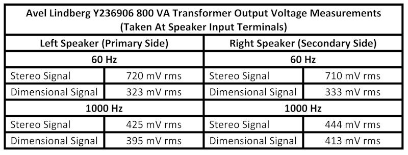
These measurements were taken at the left and right speaker inputs on 10/12/2008 with a TDK 2012 oscilloscope. The transformer was an Avel Lindberg Y236906 800VA isolation transformer. The signals were 1000 Hz and 60 Hz test signals from a test CD.
 Proud and loyal citizen of the Digital Domain and Solid State Country!
 -
Am I understanding your test procedure correctly?
The "balance adjustment" was biased to the left channel at 60hz, but biased to the right channel at 1Khz. Either way, the right speaker's SDA input (secondary side of the transformer) received higher voltage than the left speaker?
The difference between the (stereo) channels at 60 hz is 10mV, as is the difference between the sda channels. The 10 mV lower-powered stereo signal produced a 10 mV lower-powered SDA signal at the other speaker. Not at all what I'd predicted. In fact, almost exactly the opposite. With transformer losses and the winding turns-ratio difference, the SDA signal at the left speaker should have been significantly lower than it was.
OTOH, at 1K, the secondary side of the transformer DOES provide a considerable SDA boost over the primary side, just as I had assumed. The lower-powered stereo signal produced a higher-powered SDA signal, apparently due to the transformer acting as a voltage amplifier.
Can the crossovers be manipulating the signal at < 80 or 100 hz, to skew the 60hz results???
Neither DK nor anyone else has ever complained of an inter-channel balance problem with the SDA drivers. (at least, not one that couldn't be traceable to the room interaction)
First Guess: The room, the components in the crossovers, and the balance knob on the preamp--make more difference than the Dreadnought transformer winding asymmetry.
I admit that I'm somewhat surprised. (and confused...) -
Am I understanding your test procedure correctly?
The "balance adjustment" was biased to the left channel at 60hz, but biased to the right channel at 1Khz. Either way, the right speaker's SDA input (secondary side of the transformer) received higher voltage than the left speaker?
The preamplifier's balance control was set in the center.The difference between the (stereo) channels at 60 hz is 10mV, as is the difference between the sda channels. The 10 mV lower-powered stereo signal produced a 10 mV lower-powered SDA signal at the other speaker. Not at all what I'd predicted. In fact, almost exactly the opposite. With transformer losses and the winding turns-ratio difference, the SDA signal at the left speaker should have been significantly lower than it was.
OTOH, at 1K, the secondary side of the transformer DOES provide a considerable SDA boost over the primary side, just as I had assumed. The lower-powered stereo signal produced a higher-powered SDA signal, apparently due to the transformer acting as a voltage amplifier.
Can the crossovers be manipulating the signal at < 80 or 100 hz, to skew the 60hz results???
I should have mentioned in my previous post that the SDA circuit operates from ~1600 Hz down according to Matthew Polk:
"The transformer is a 1:1 ratio and allows the L-R and R-L SDA signals to be derived while isolating the grounds of the two amp channels. The inverted portions of the SDA signals only need a bandwidth from a little below 100Hz to 1.6kHz. It's helpful if the transformer has more bandwidth on the top end since the high-end cutoff is controlled by a low-pass in the cross-over. At the low end, however, it's best if the transformer windings have a very high inductance as measured with the secondary open, around 14mh, and a very low DCR.
In the mid-range where SDA operates, the SDA drivers on one side operate in series with the SDA drivers on the other side with the signals passing through one set of SDA drivers then through the transformer and then through the set of SDA drivers on the other side. However, at low frequencies the positive part of the signal passes through the SDA drivers and is shunted directly to ground by an inductor in parallel with the transformer. The result is that the SDA drivers operate in parallel with the stereo drivers at low frequencies but operate in series with the other side to produce the SDA difference signal in the mid-range. If the DCR is too high, as it was in the original isolation transformer, it will reduce the level of the SDA signal and alter the bandwidth. If the inductance isn't high enough, also the case in the original, it will raise the low-end cutoff of the SDA signal further reducing the SDA soundstage and allow the SDA drivers to produce too much upper bass thereby muddying the sound.
The transformer in the SRT controller had a DCR around .3 ohms and an inductance around 14mh as best I recall. Current carrying capability before saturation is also an issue and was not adequate with the original. I think it was only about 3 amps which would be about 60 watts to the SDA drivers and not enough. I don't recall exactly what it was in the SRT but seem to recall something like 10 amps which would deliver about 600 watts to the SDA drivers.
As a practical matter we found the only way to get a low enough DCR was with a 1:1 toroidal transformer. These are available off the shelf but expensive. Because of the efficiency of the toroid the cores must be much larger to avoid saturation."Neither DK nor anyone else has ever complained of an inter-channel balance problem with the SDA drivers.
Not that I know of.First Guess: The room, the components in the crossovers, and the balance knob on the preamp--make more difference than the Dreadnought transformer winding asymmetry.
That seems reasonable.Proud and loyal citizen of the Digital Domain and Solid State Country! -
Or it's just that our ears really aren't that sensitive to notice such nuance. One thing is certain, the DreadNought rules.Good music, a good source, and good power can make SDA's sing. Tubes make them dance.
-
DarqueKnight wrote: »The preamplifier's balance control was set in the center.
He meant that the results of your tests show a balance bias to the left at 60hZ and to the right at 1000Hz.Political Correctness'.........defined
"A doctrine fostered by a delusional, illogical minority and rabidly promoted by an unscrupulous mainstream media, which holds forth the proposition that it is entirely possible to pick up a t-u-r-d by the clean end."
President of Club Polk -
First Guess: The room, the components in the crossovers, and the balance knob on the preamp--make more difference than the Dreadnought transformer winding asymmetry.
In addition to all of the above, I would think that the slight difference in gain between the channels of a stereo amp, or a pair of monoblocks, would also be a factor.I admit that I'm somewhat surprised. (and confused...)
We should never be surprised at the behavior of "unconventional" loudspeakers.Or it's just that our ears really aren't that sensitive to notice such nuance.
Maybe not. In terms of dB, the differences in voltage amplitudes between channels are:
60 Hz
0.12 dB stereo, 0.26 dB dimensional.
1000 Hz
0.38 dB stereo, 0.39 dB dimensional.
With all of the things going on in a stereo sound field, it is not difficult for me to accept that most people would not notice a difference of 0.1 dB to 0.4 dB difference in sound level between channels.He meant that the results of your tests show a balance bias to the left at 60hZ and to the right at 1000Hz.
In the future, when I am more dedicated to audio than I am now, I will do a more detailed set of measurements covering the full range of the SDA bandwidth using different amplifiers.Proud and loyal citizen of the Digital Domain and Solid State Country! -
For those who wanted to get one of these AL 1000VA transformers, I'm getting another group buy going, please post here:
http://www.polkaudio.com/forums/showthread.php?134643-Group-buy-Avel-Lindberg-1000VA-isolation-transformers-for-DreadNought&p=1796961#post1796961Good music, a good source, and good power can make SDA's sing. Tubes make them dance. -
DarqueKnight wrote: »The preamplifier's balance control was set in the center.
I have a couple of followup questions about the test setup. You took the measurements at the speaker connection on the crossover, correct? Were the speakers attached to the crossover when you took the readings?
My understanding of the SDA circuit is that the SDA cable (or transformer) only passes the difference between the left and right channel. If the balance control was in the middle, was the test tone only present on one channel at a time? With your scope it should be possible to measure multiple points simultaneously (can't see your entire scope, but assuming it is 4 ch like mine). You could measure input (from amp), output to stereo, output to L dim, and output to r dim. For testing the transformer I would think only 1 side should have a signal, so turn the balance control all the way to one side.
The differences in left and right measurements at 60Hz and 1kHz could be due to tolerances of caps and inductors in LC low pass, windings in the transformer, noise picked up by the scope, and / or digitization limits of the scope (8 bit). There is no uncertainty specified in the measurement, I would think +/- 5mv would be reasonable. At that point it is hard to even say there actually is a statistically significant difference in L and R.
Just some food for thought. Given, when you did the testing I can't imagine you would be setup or inclined to do any additional testing. I have enjoyed reading a number of your posts. -
I have a couple of followup questions about the test setup. You took the measurements at the speaker connection on the crossover, correct? Were the speakers attached to the crossover when you took the readings?
Yes. The crossovers had been reinstalled in the speakers and the speakers were connected by the transformer.My understanding of the SDA circuit is that the SDA cable (or transformer) only passes the difference between the left and right channel. If the balance control was in the middle, was the test tone only present on one channel at a time?
The test tone was applied to both channels.With your scope it should be possible to measure multiple points simultaneously (can't see your entire scope, but assuming it is 4 ch like mine).
My scope is two channel.You could measure input (from amp), output to stereo, output to L dim, and output to r dim. For testing the transformer I would think only 1 side should have a signal, so turn the balance control all the way to one side.
Per recommendation from Polk, I thought a test that was more representative of how the speakers are connected in actual use would be more useful. However, I agree that the test scenario you describe would be useful for comparative purposes.The differences in left and right measurements at 60Hz and 1kHz could be due to tolerances of caps and inductors in LC low pass, windings in the transformer, noise picked up by the scope, and / or digitization limits of the scope (8 bit). There is no uncertainty specified in the measurement, I would think +/- 5mv would be reasonable. At that point it is hard to even say there actually is a statistically significant difference in L and R.
I agree. The difference between output levels of the amplifier channels might also be a significant factor.Just some food for thought. Given, when you did the testing I can't imagine you would be setup or inclined to do any additional testing.
Your points are well taken and I will consider doing additional testing.Proud and loyal citizen of the Digital Domain and Solid State Country! -
For any fellow newcomers to the Forum who own vintage Polk SDAs and are contemplating modifying them to bring them into the 21st century, I would suggest that this thread and its predecessor -- "The AI-1 Dreadnought Project Pt. 1" -- are "required" reading. I've read through them several times now, and continue to gain knowledge that helps me along the way in my "mods" work on SDA SRS 1.2s and 1Cs.Family Room, Innuos Statement streamer (Roon Core) with Morrow Audio USB cable to McIntosh MC 2700 pre with DC2 Digital Audio Module; AQ Sky XLRs to CAT 600.2 dualmono amp, Morrow Elite Speaker Cables to NOLA Baby Grand Reference Gold 3 speakers. Power source for all components: Silver Circle Audio Pure Power One with dedicated 20 amp circuit to main panel.
Exercise Room, Innuos Streamer via Cat 6 cable connection to PS Audio PerfectWave MkII DAC w/Bridge II, AQ King Cobra RCAs to Perreaux PMF3150 amp (fully restored and upgraded by Jeffrey Jackson, Precision Audio Labs), Supra Rondo 4x2.5 Speaker Cables to SDA 1Cs (Vr3 Mods Xovers and other mods.), Dreadnaught with Supra Rondo 4x2.5 interconnect cables by Vr3 Mods. Power for each component from dedicated 20 amp circuit to main panel, except Innuos Statement powered from Silver Circle Audio Pure Power One. -
The Avel Lindberg 1000VA AV-047548 uses the same wire color scheme as the 800VA Y23-6906.
Primary Side
Grey/Brown (+)
Blue/Violet (-)
Secondary Side
Red/Yellow (+)
Black/Orange (-)Proud and loyal citizen of the Digital Domain and Solid State Country! -
Sal,
I know you wanted me to build you another case for the NL4's but how bout I send you another face plate for the back end of yours and you modify it to fit the back of the case you have and drill the holes you need for the NL4's..
Let me know!! -
because we are waiting for special order parts to come in so I have time....
Let me guess.... Jantzen inductors?Good music, a good source, and good power can make SDA's sing. Tubes make them dance. -
-
Sal I have an extra one here. I think your front plate was 1/8" thick..
-
We are waiting on Jantzen inductors... :-P- Not Tom ::::::: Any system can play Diana Krall. Only the best can play Limp Bizkit.