Monitor 4 upgrades
Comments
-
After looking into this thread, I've decided to make this a public comment.
Refrain from being hostile in your comments towards others. Sound is too subjective of an experience to put others down for their opinions. This applies to everyone to has engaged in this discourse on this thread and others. You can peacefully speak your opinion without personally attacking others and veering off course of what the thread was originally posted about.
I personally like when people take it upon themselves to mod their gear, I do a lot of that with my own studio gear ranging from microphones to audio hardware, I have yet to crack into home audio gear like DeRod has done here but I commend him for it. If you do not have anything nice or constructive to say, then move on.
This forum will continue to degrade if frequent users continue to be negative towards others who are just sharing their experiences. Going forward, I will be more strict on how I handle these arguments that pop up from time to time. Keep it focused on audio, be friendly towards one another, don't further push this forum into a pit of negativity. We would rather have new users who are welcomed into the community than to alienate those who can bring new perspectives into the forums.
Otherwise, @DeRod, please continue with the build, I am curious to see what comes of it.
-
Gardenstater wrote: »@Ryan_Soundunited Any chance we could get this schematic posted in the Vintage Speaker section under Schematics (all except SDA)? Probably only the 2nd schematic we have existing of the Peerless days.
We have three versions of this model in our post here https://forum.polkaudio.com/discussion/38755/polk-audio-speaker-wiring-schematics-amp-more-all-models-except-sda
If we can get a picture of the tweeter's rear to see what version it is, we can let you guys know which version of the schematic to use. -
Ryan_Soundunited wrote: »Gardenstater wrote: »@Ryan_Soundunited Any chance we could get this schematic posted in the Vintage Speaker section under Schematics (all except SDA)? Probably only the 2nd schematic we have existing of the Peerless days.
We have three versions of this model in our post here https://forum.polkaudio.com/discussion/38755/polk-audio-speaker-wiring-schematics-amp-more-all-models-except-sda
If we can get a picture of the tweeter's rear to see what version it is, we can let you guys know which version of the schematic to use.
Yeah. Those are the later models that came after the M4 that had 8 ohm Peerless tweeter plus 8 ohm MW6500. Those later models are the M4A which used 4 ohm tweeter and midwoofer and the M4 Series 2 that came after that.
The schematic that DeRod posted is the one that is the early one and is missing from the archives, like most of the schematics for Peerless tweeter days for some curious reason which I have never heard explained.George / NJ
Polk 7B main speakers, std. mods+ (1979, orig owner)
Martin Logan Dynamo sub w/6ft 14awg Power Cord
Onkyo A-8017 integrated
Logitech Squeezebox Touch Streamer w/EDO applet
iFi nano iDSD DAC
iPurifier3
iDefender w/ iPower PS
Custom Steve Wilson 1m UPOCC Interconnect
iFi Mercury 0.5m OFHC continuous cast copper USB cable
Custom Ribbon Speaker Cables, 5ft long, 4N Copper, 14awg, ultra low inductance
Custom Vibration Isolation Speaker Stands and Sub Platform -
Gardenstater wrote: »Ryan_Soundunited wrote: »Gardenstater wrote: »@Ryan_Soundunited Any chance we could get this schematic posted in the Vintage Speaker section under Schematics (all except SDA)? Probably only the 2nd schematic we have existing of the Peerless days.
We have three versions of this model in our post here https://forum.polkaudio.com/discussion/38755/polk-audio-speaker-wiring-schematics-amp-more-all-models-except-sda
If we can get a picture of the tweeter's rear to see what version it is, we can let you guys know which version of the schematic to use.
Yeah. Those are the later models that came after the M4 that had 8 ohm Peerless tweeter plus 8 ohm MW6500. Those later models are the M4A which used 4 ohm tweeter and midwoofer and the M4 Series 2 that came after that.
The schematic that DeRod posted is the one that is the early one and is missing from the archives, like most of the schematics for Peerless tweeter days for some curious reason which I have never heard explained.
Maybe denote that in this case on this schematic mark it Peerless tweeter to denote it is not the SL1000 tweeter which also has been referred to as HF 1000 on some schematics. -
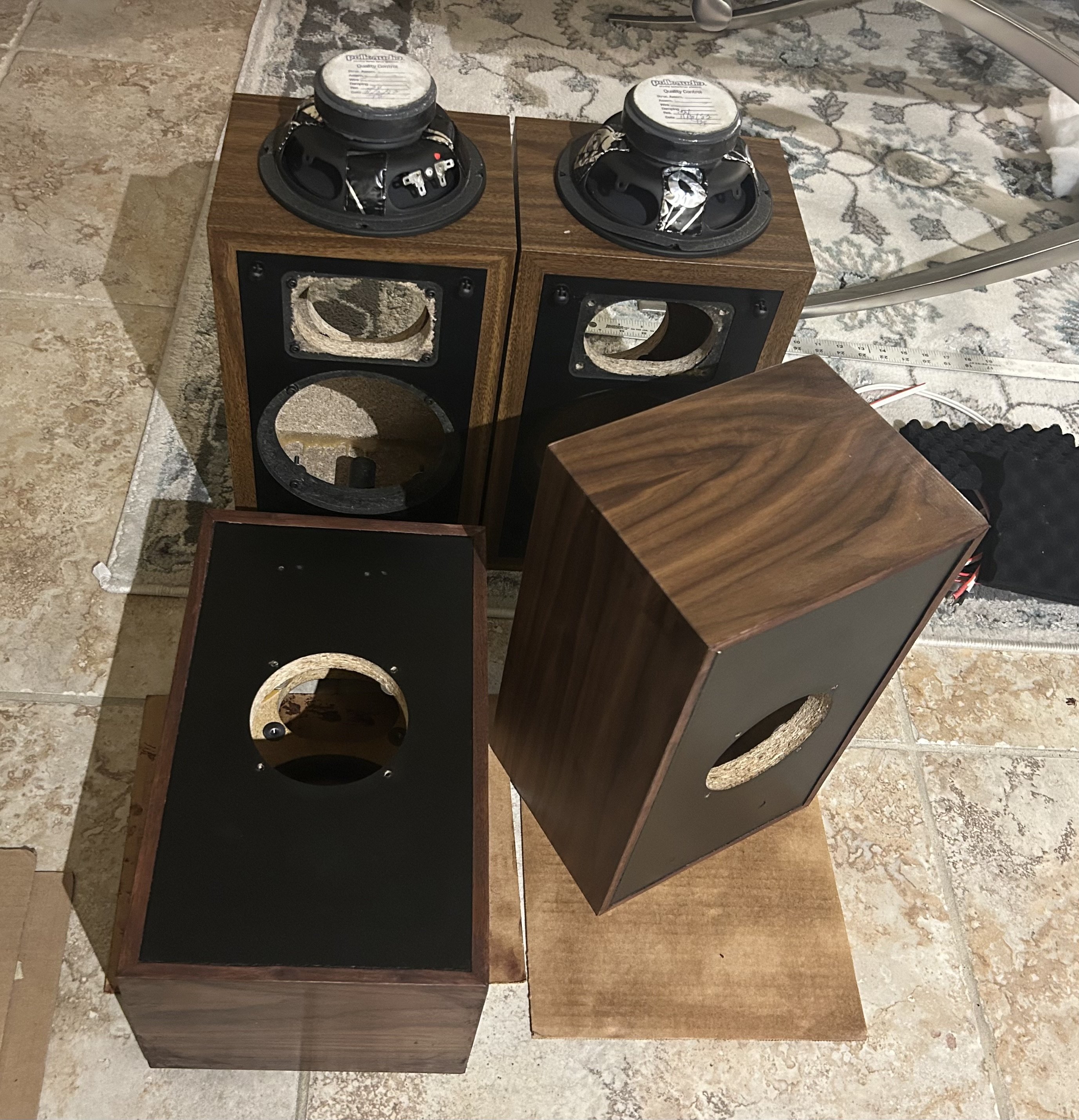
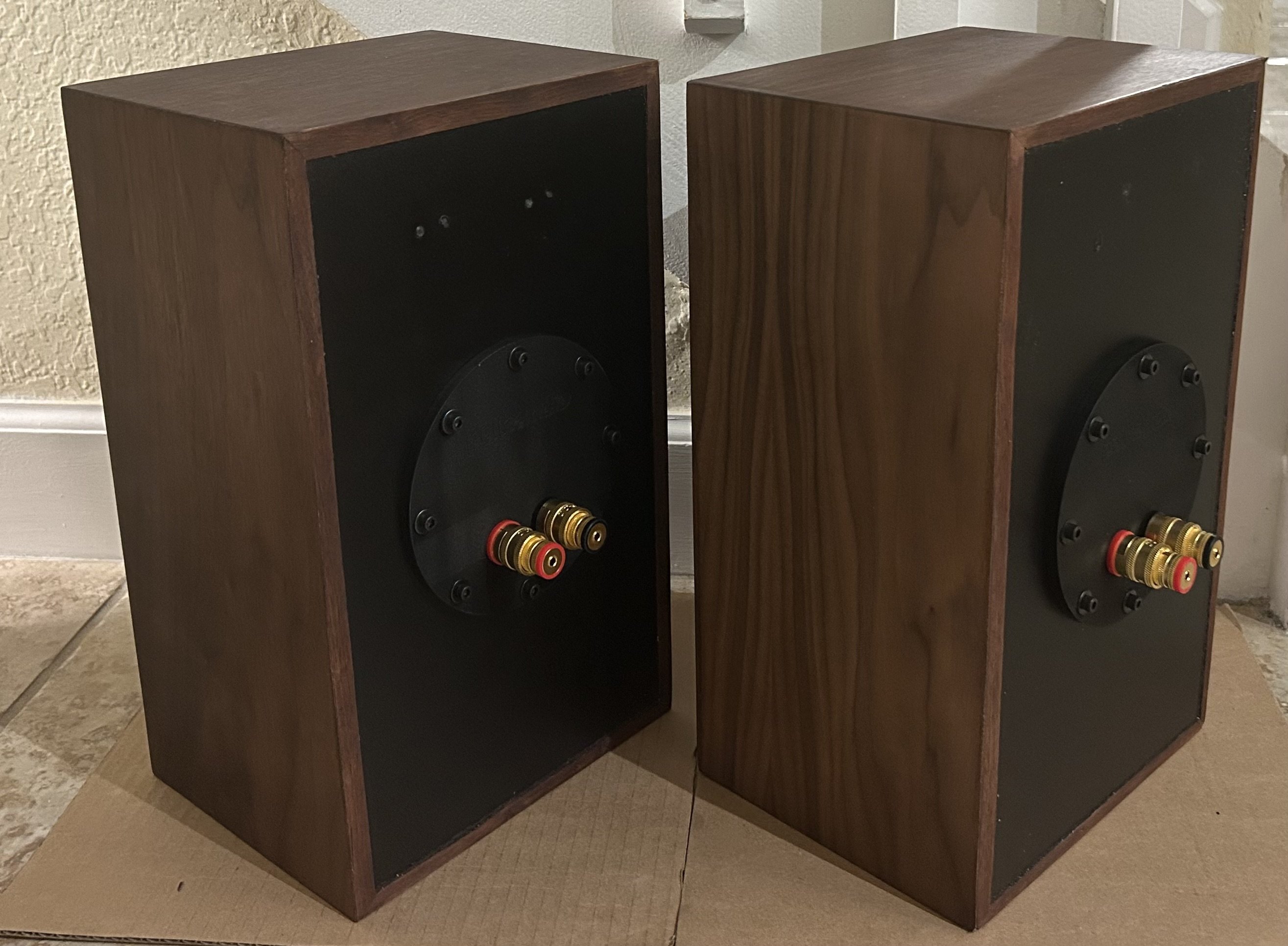
Needs just a little more light sanding and the clear coat to finish the 1st pair.
I think it would be cool to see what these sounds like if I swap out the MW6500 for the MW6502. Cool thing is I got 2 pair and could actually compare them to one another. Ordering some crossover parts as well."Equality is a myth to protect the weak. Some of us are strong in the Force, others are not. Only a fool believes otherwise." - Sith Proverb. -
Nice shade of brown. Did you wipe afterwards?
 The Gear... Carver "Statement" Mono-blocks, Mcintosh C2800 Arcam AVR20, Oppo UDP-203 4K Blu-ray player, Sony XBR70x850B 4k, Polk Audio Legend L800 with height modules, L400 Center Channel Polk audio AB800 "in-wall" surrounds. Marantz MM7025 stereo amp. Simaudio Moon MiND2 Shunyata Triton
“When once a Republic is corrupted, there is no possibility of remedying any of the growing evils but by removing the corruption and restoring its lost principles; every other correction is either useless or a new evil.”— Thomas Jefferson
How many flies need to be buzzing a dead horse before you guys stop beating it? -
Wouldn't it be inconsiderate to others if I didn't? 🤣 j/k
I didn't finish them with anything that's the natural color, brown. It's a walnut veneer. I just sanded them and oiled them with that cheap lemon oil. That real linseed oil is expensive!
"Equality is a myth to protect the weak. Some of us are strong in the Force, others are not. Only a fool believes otherwise." - Sith Proverb. -
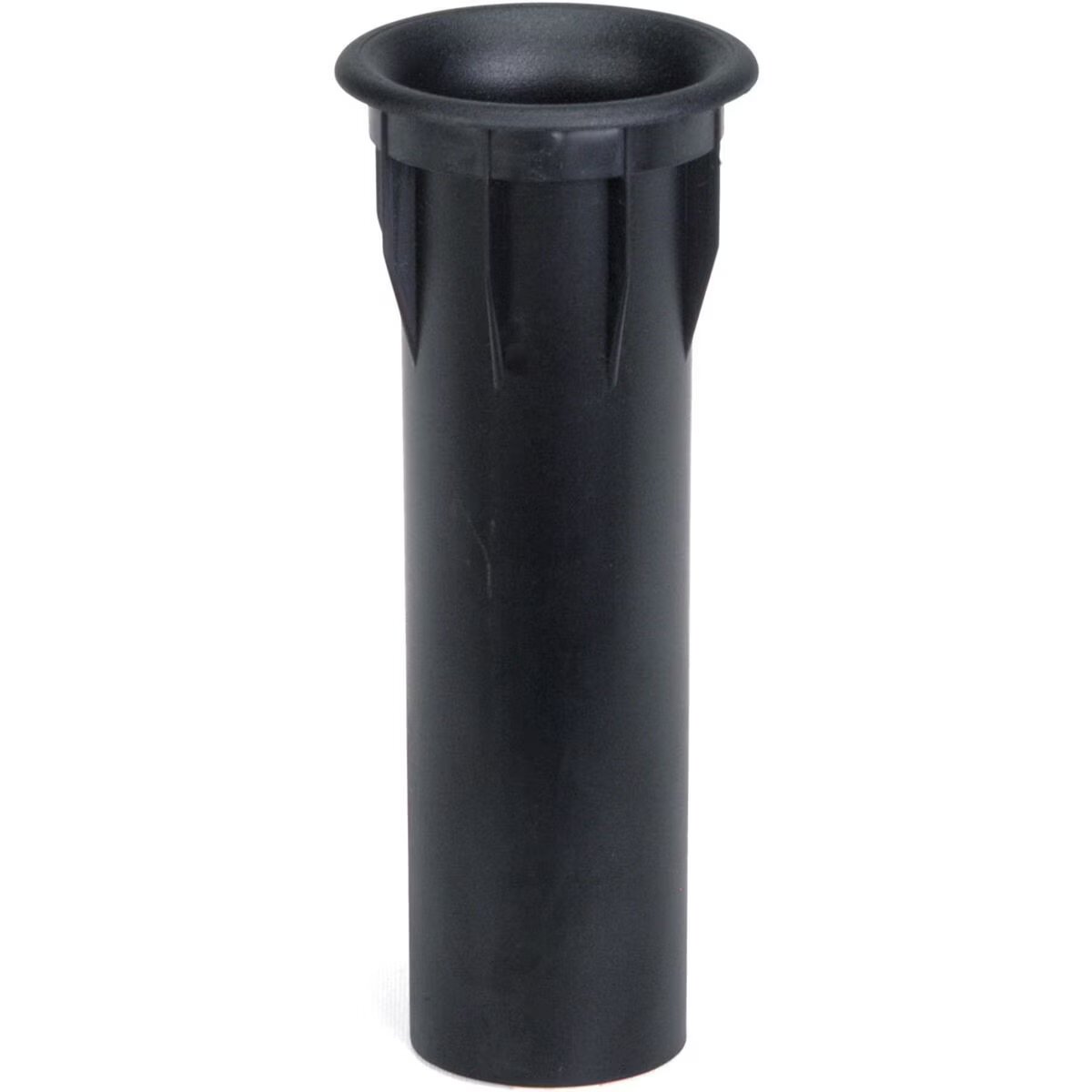
Going experiment with a new style port tube. Something like that that would reach the front with the flared opening. Same length and diameter.
"Equality is a myth to protect the weak. Some of us are strong in the Force, others are not. Only a fool believes otherwise." - Sith Proverb. -
Good idea. I changed the port diameter and length, plus flared exit on 2 of the Billet-faced 5Jr's I built. It got rid of the chuffing at higher volumes.Don't take experimental gene therapies from known eugenicists.
-
George / NJ
Polk 7B main speakers, std. mods+ (1979, orig owner)
Martin Logan Dynamo sub w/6ft 14awg Power Cord
Onkyo A-8017 integrated
Logitech Squeezebox Touch Streamer w/EDO applet
iFi nano iDSD DAC
iPurifier3
iDefender w/ iPower PS
Custom Steve Wilson 1m UPOCC Interconnect
iFi Mercury 0.5m OFHC continuous cast copper USB cable
Custom Ribbon Speaker Cables, 5ft long, 4N Copper, 14awg, ultra low inductance
Custom Vibration Isolation Speaker Stands and Sub Platform -
I don't think your air holes are sized properly.Expert Moron Extraordinaire
You're just jealous 'cause the voices don't talk to you! -
There's always a Power-Port retro fit option too
") Don't take experimental gene therapies from known eugenicists.
Don't take experimental gene therapies from known eugenicists. -
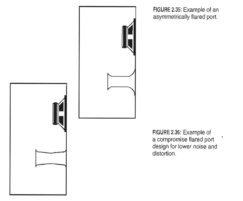
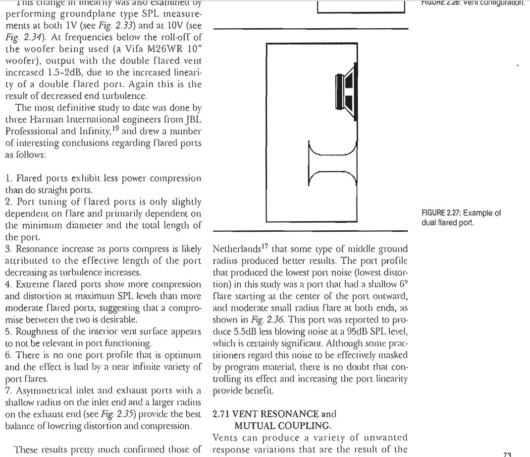
The Thiel patent says: "The length of the vent tube is a function of the radius of the vent tube such that a larger vent radius requires a longer vent tube. Generally speaking, it is desired to use a vent tube having as large a radius as possible."
So, figuring out the longest possible tube that can fit, even in a small enclosure such as this, is a good way to go to optimize sound quality. In this patent they even recommend an angular orientation going diagonally through the enclosure with an elliptical opening that also represents a desirable entrance flare. According to generally accepted guidelines (ref. Loudspeaker Design Cookbook) you do not want to have the end of the vent be closer than 3 in. from any enclosure walls which severely limits how long of a port they were able to fit in the M4, being that the early versions had an enclosure outer dimension depth of only 6-3/4 in., later increased to 7-3/8 in. in the later M4 and the M4A and then even further to 7-1/2 in. in the M4 Series 2 where they were able to get the -3dB point down to 53 Hz from 55 Hz in the M4. It also seems like they increased the diameter of the port in the M4 Series 2 to around 1.5 in. (judging from photos), from 7/8 in. in the M4 and M4A.
https://worldwide.espacenet.com/patent/search/family/022469952/publication/US4785908A?q=pn=US4785908A
M4 Series 2 port, with what looks like a small bevel added: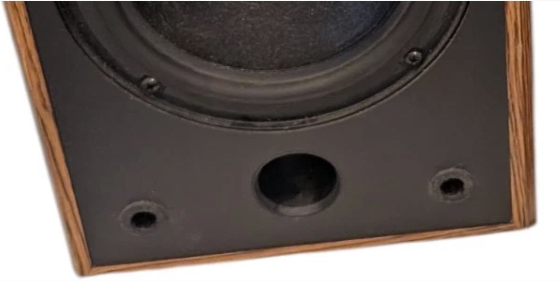
George / NJ
Polk 7B main speakers, std. mods+ (1979, orig owner)
Martin Logan Dynamo sub w/6ft 14awg Power Cord
Onkyo A-8017 integrated
Logitech Squeezebox Touch Streamer w/EDO applet
iFi nano iDSD DAC
iPurifier3
iDefender w/ iPower PS
Custom Steve Wilson 1m UPOCC Interconnect
iFi Mercury 0.5m OFHC continuous cast copper USB cable
Custom Ribbon Speaker Cables, 5ft long, 4N Copper, 14awg, ultra low inductance
Custom Vibration Isolation Speaker Stands and Sub Platform -
."Equality is a myth to protect the weak. Some of us are strong in the Force, others are not. Only a fool believes otherwise." - Sith Proverb.
-
Correction to what I said above. Apparently the 7-3/8 in. depth was including the grille cover (of course), and the 6-3/4" was without grille cover, so they probably had 7-3/8 in. from the very start with a typical 5/8 in. thick grille. They did increase cabinet volume slightly with the M4 Series 2 though, by adding 1/4 in. to the height and maybe(?) 1/8 in. to the depth although that could've been the grille. Don't know. But increasing cabinet volume and increasing port length would both reduce the port tuning frequency.George / NJ
Polk 7B main speakers, std. mods+ (1979, orig owner)
Martin Logan Dynamo sub w/6ft 14awg Power Cord
Onkyo A-8017 integrated
Logitech Squeezebox Touch Streamer w/EDO applet
iFi nano iDSD DAC
iPurifier3
iDefender w/ iPower PS
Custom Steve Wilson 1m UPOCC Interconnect
iFi Mercury 0.5m OFHC continuous cast copper USB cable
Custom Ribbon Speaker Cables, 5ft long, 4N Copper, 14awg, ultra low inductance
Custom Vibration Isolation Speaker Stands and Sub Platform -
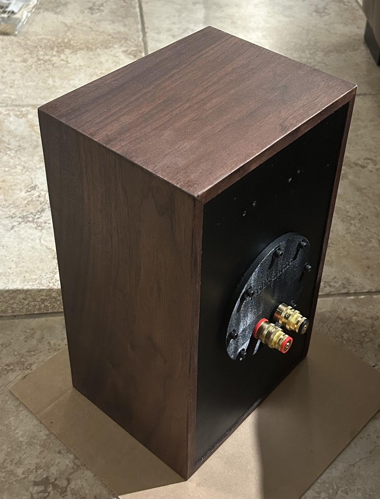
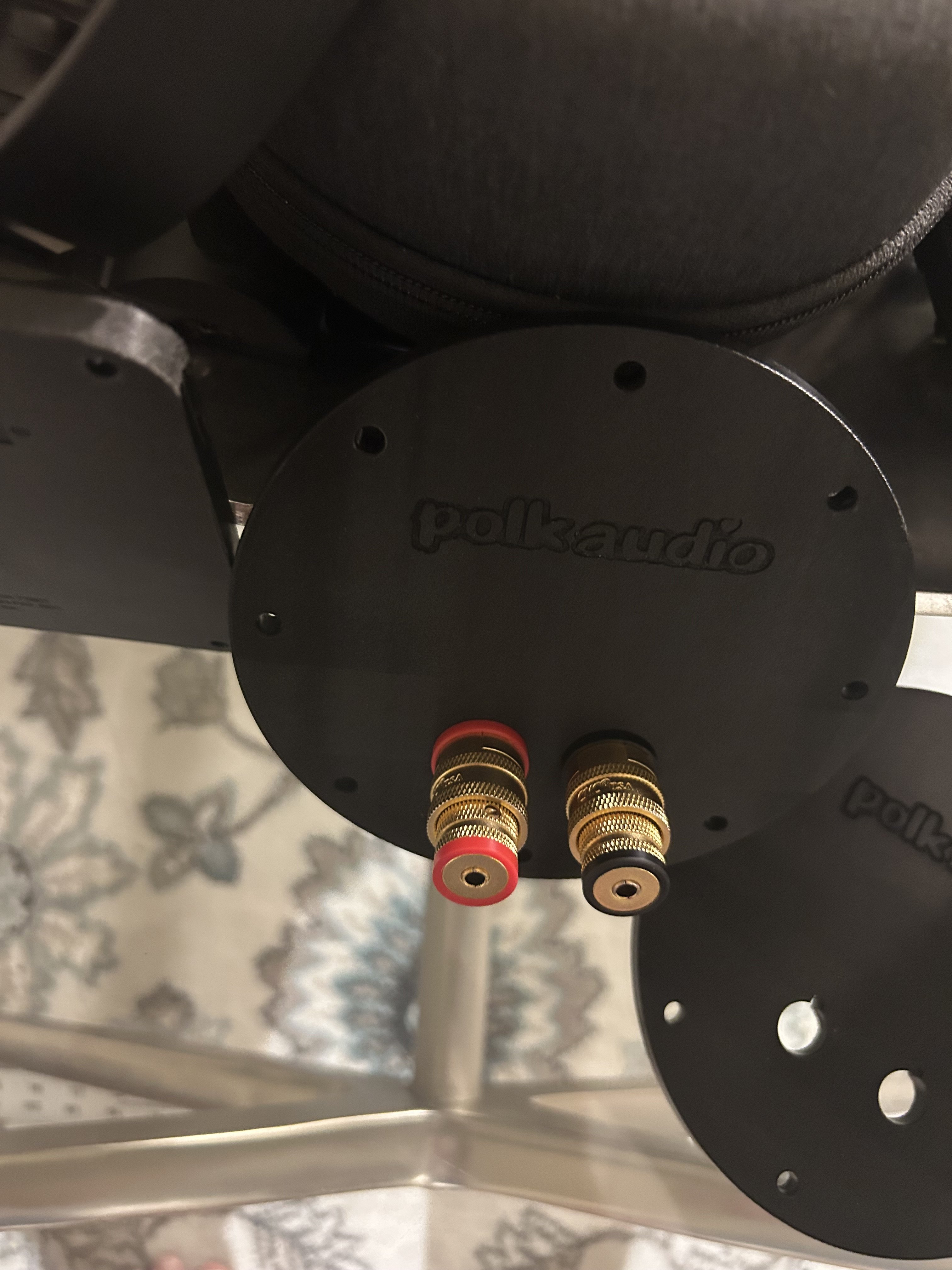
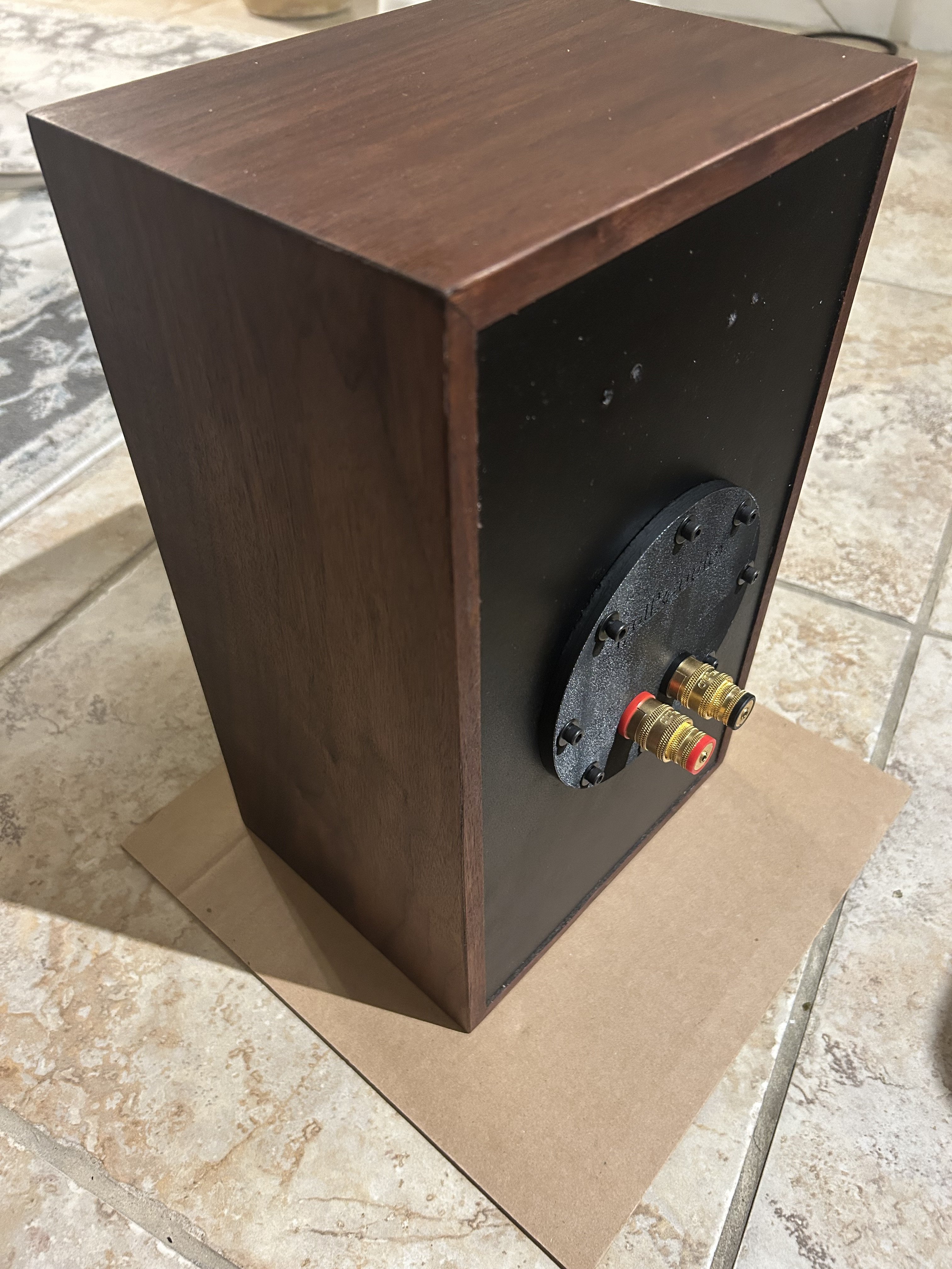
Some big binding posts on the little speakers.
"Equality is a myth to protect the weak. Some of us are strong in the Force, others are not. Only a fool believes otherwise." - Sith Proverb. -
"Equality is a myth to protect the weak. Some of us are strong in the Force, others are not. Only a fool believes otherwise." - Sith Proverb. -
Next. External backpack Duelund crossover network. 🤣 Nice work. I think there are more interesting surprises in store for those who appreciate this thread. 👌George / NJ
Polk 7B main speakers, std. mods+ (1979, orig owner)
Martin Logan Dynamo sub w/6ft 14awg Power Cord
Onkyo A-8017 integrated
Logitech Squeezebox Touch Streamer w/EDO applet
iFi nano iDSD DAC
iPurifier3
iDefender w/ iPower PS
Custom Steve Wilson 1m UPOCC Interconnect
iFi Mercury 0.5m OFHC continuous cast copper USB cable
Custom Ribbon Speaker Cables, 5ft long, 4N Copper, 14awg, ultra low inductance
Custom Vibration Isolation Speaker Stands and Sub Platform -
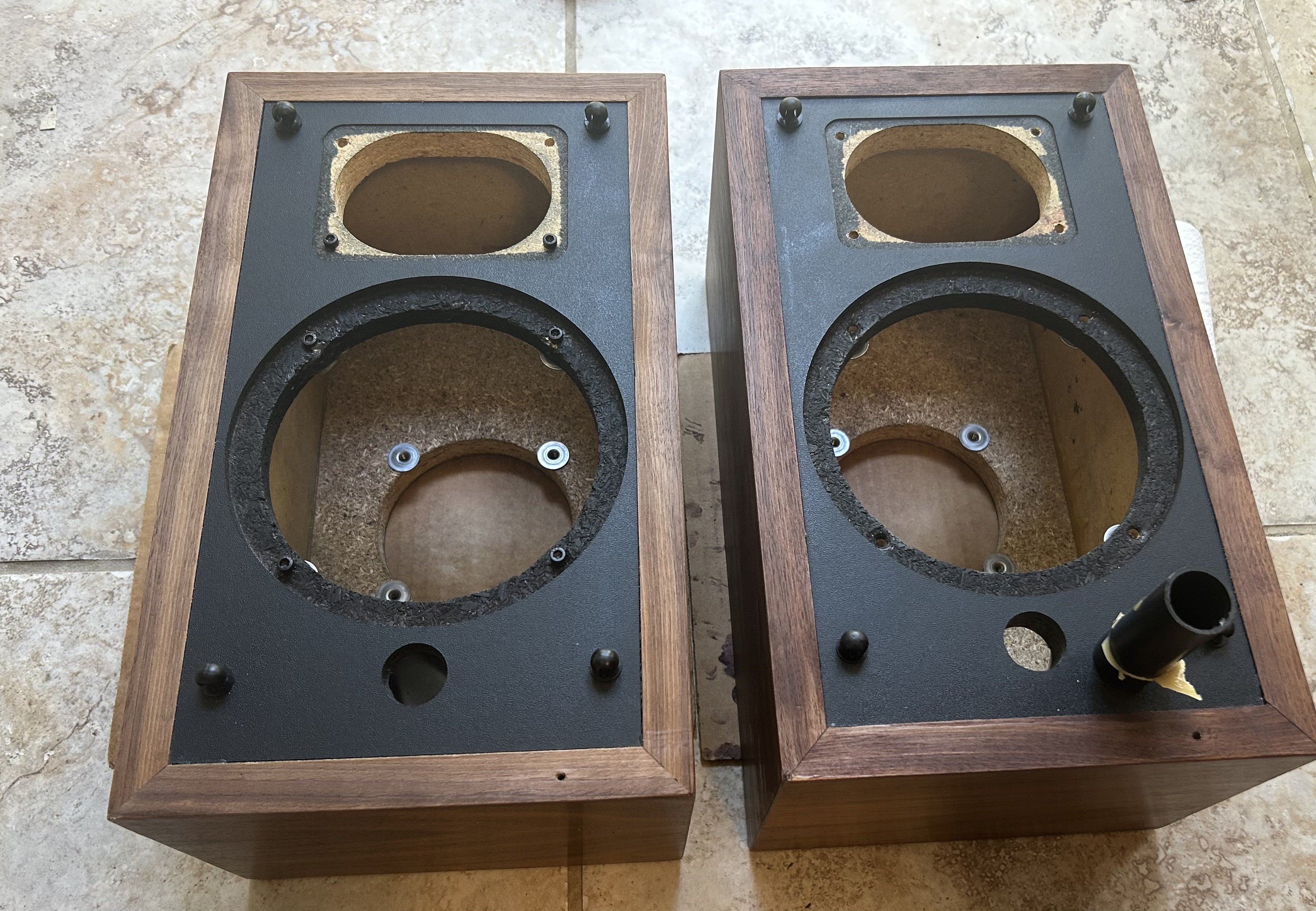
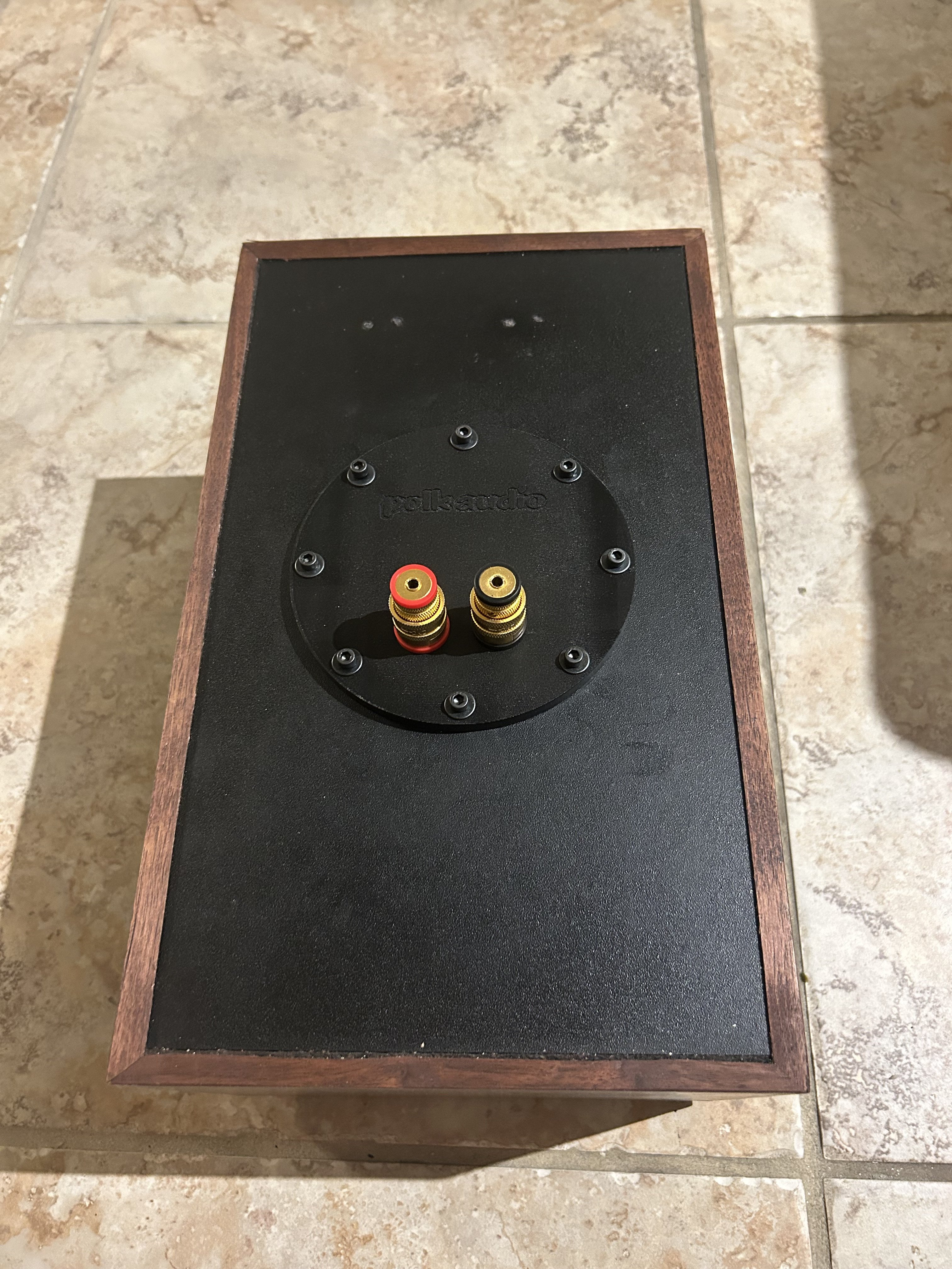
I think there's going to end up being a structural failure of the rear baffle on at least one of those speakers given how uncentered the binding post plates are and how close to the edge of the hole at least 3 of the plate mounting screws are.
If that's the surprises you're talking about, I'm in full agreement!Expert Moron Extraordinaire
You're just jealous 'cause the voices don't talk to you! -
The plates are well made and everything lines up equally. All the bolts are equal distance from the edges.
One easy and safe way to determine if your bolts and nuts line up is to only hand tighten the bolts to the bottom. If you can't tighten it down by hand back it out and try again. If you need a screwdriver to tighten it down something's wrong.
That's the reason I like bolts better than screws because they are easier to grab with your fingers.
Pay attention you might learn something."Equality is a myth to protect the weak. Some of us are strong in the Force, others are not. Only a fool believes otherwise." - Sith Proverb. -
You sound like you’re going to be changing the oil after 5000 hrs of playing, it’s just a binding post plate, my guess you’d be lucky to have to take it off again in its lifetime.
And they should be snug enough that you can’t loosen them with your fingers..
Yet you keep calling others a clown 🤡 and it seems to be accepted from the powers that be.. -
The bolts should tighten down by hand smooth. The last couple of turns with a screw driver once you’re ready to tighten down everything. Obviously once tighten down you can’t remove them with your fingers.
I have know idea what changing your oil had to do with my speakers 🤡 and I’m glad 🤣🤣."Equality is a myth to protect the weak. Some of us are strong in the Force, others are not. Only a fool believes otherwise." - Sith Proverb. -
This thread has more flags than the Lions or Browns at halftime. Ya doing something right.Don't take experimental gene therapies from known eugenicists.
-
I didn't buy a pair of local M4 (I don't like the tweeter on the ones I posted).
But your build made me put them on my watch list")
[watches in Gowron]
The Thrifty Setups in Mah House Big thrifty stereo in the basement w/ my custom SDA-1C (built with help from kind forum members) * Beautiful 1966 MCM GE console upgraded w/ Bluetooth, Dual turntable, and Paradigm speakers in family room * Swanky 1980 Realistic system and great TEAC eq with dancing colored lights in the living room * custom 5B on a system for my Dad * Ye Olde college stereo in the garage -
I hope he isn't our new moderator. What's the Klingon word for schadenfreude? That's how he looks.George / NJ
Polk 7B main speakers, std. mods+ (1979, orig owner)
Martin Logan Dynamo sub w/6ft 14awg Power Cord
Onkyo A-8017 integrated
Logitech Squeezebox Touch Streamer w/EDO applet
iFi nano iDSD DAC
iPurifier3
iDefender w/ iPower PS
Custom Steve Wilson 1m UPOCC Interconnect
iFi Mercury 0.5m OFHC continuous cast copper USB cable
Custom Ribbon Speaker Cables, 5ft long, 4N Copper, 14awg, ultra low inductance
Custom Vibration Isolation Speaker Stands and Sub Platform -
He appears to have enjoyed some interstellar gummies.Don't take experimental gene therapies from known eugenicists.
-
Gardenstater wrote: »I hope he isn't our new moderator. What's the Klingon word for schadenfreude? That's how he looks.
I believe the Germanic word you are looking for is doppelganger...
Don't take experimental gene therapies from known eugenicists. -
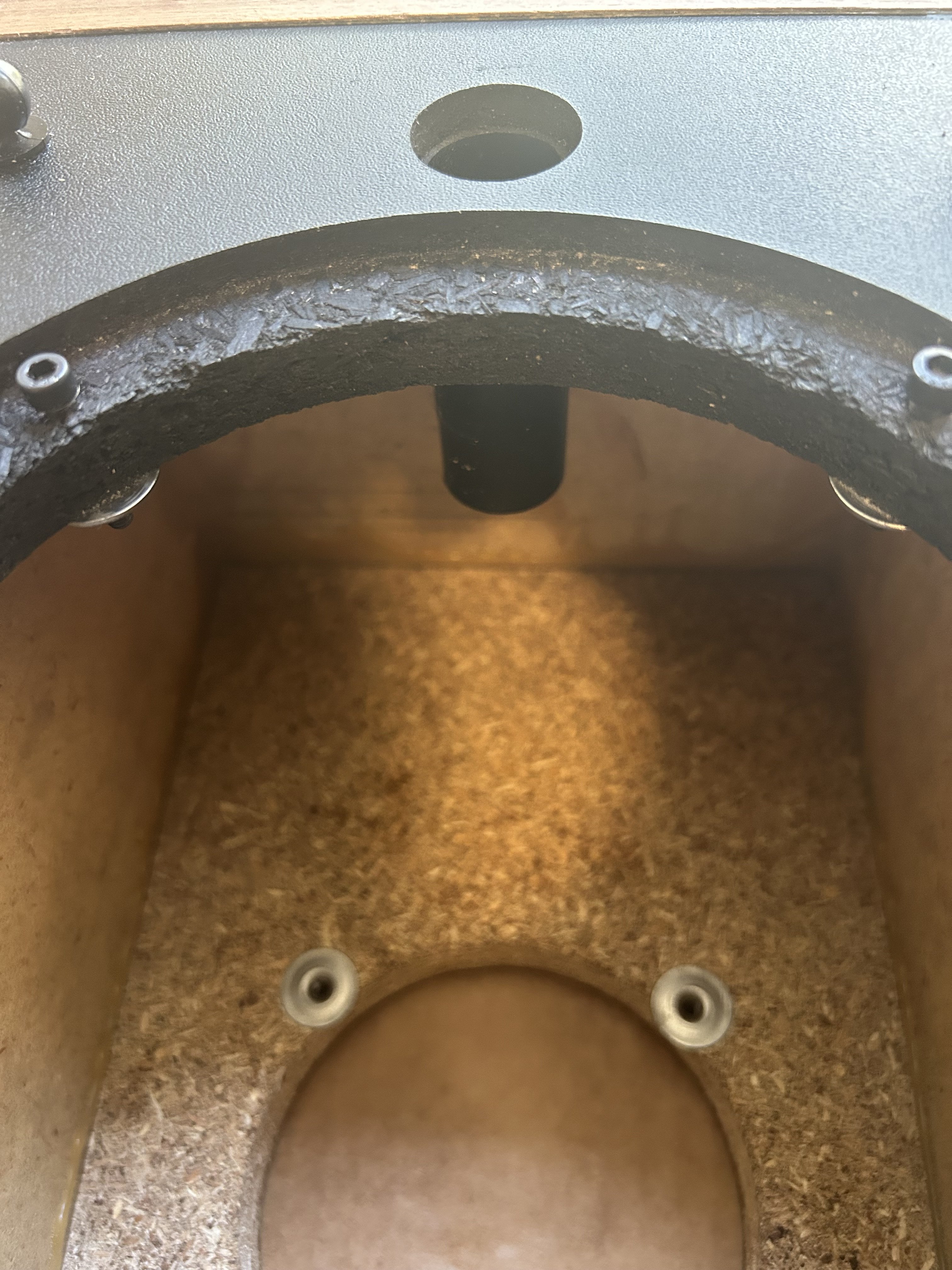
You can't, honestly, look at this picture and tell me all those "bolts" are equidistant from the binding post plate hole edge
Your "bolts" are tee-nuts too and the day you cinch down on them, where ever the tee-nut flange doesn't have the same amount of material under it to snug down on, it's going to tend to crush the edge of the particle board leading to failure.
For those who don't know what tee-nuts are, they are these: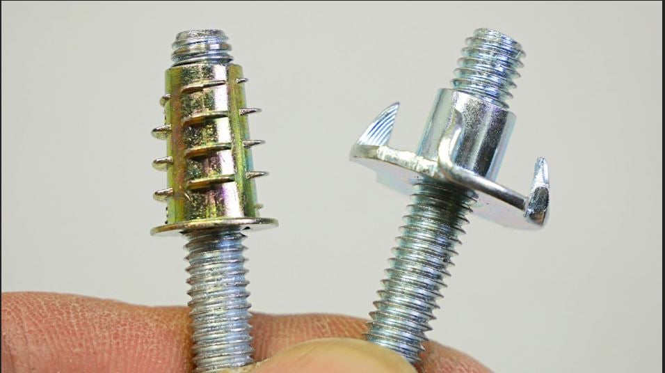
They require pre-drilling and are sometimes called sleeve nuts, threaded flanges or threaded sleeves. Whether you use the spiked flange kind, the non-spiked flange kind or you use the kind that gets threaded in to the hole, they rely on clamping force to remain in position and maintain fastening tension. If you do not have the entirety of the flange contacting the material you are using the tee-nut for you will not get even clamping force and, additionally, you will create forces on the rest of the flange and spikes that they were not designed to handle. That makes them weaker and more prone to crushing the material they are mounted in and failing or ripping out. Add to the fact that it's a particle board enclosure with not much capability to hold screw tensions and this is looking at failure.
Once it fails, the only repair is going to be cut a new, larger plate to hold the binding posts and then drill new holes for new screw holes and you'll have to make sure your new holes are far enough out from the old holes to make sure you don't compromise the new holes with the failed old holes. You'll also have to seal that whole thing up and the larger the plate, the more screws you will need to ensure equal clamping force around the perimeter gasket of the binding post plate. The more screw holes you punch in the particle board the more likely you are to be making a perforation pattern that creates a failure point.
Particle board is nothing more than coarse sawdust that is mixed with a resin and then "printed" into sheets which are then compressed and heated to create a contiguous product that is temperature stable and sonically dead (it doesn't resonate). It lacks the structural stability of other engineered products like plywood and is susceptible to damage from moisture or impact. It's not the greatest thing for building cabinets but it is inexpensive, strength/stability can be improved with lamination and it has very little waste in the manufacturing process. That makes it ideal for mass speaker manufacturing which is why so many brands use it. It is not real happy when it gets disassembled because once the tension on particles that are holding mounting screws in place is released, they tend to fall out of suspension in the resin which, in turn, leaves less material for the screw being returned to it's position to create tension on. In other words, it leaves a weaker hole. That can hamper re-assembly and reduce longevity of the product.
Something like a tee-nut can solve that problem but you have to use them correctly or they will just clamp down unevenly and rip out of an edge.
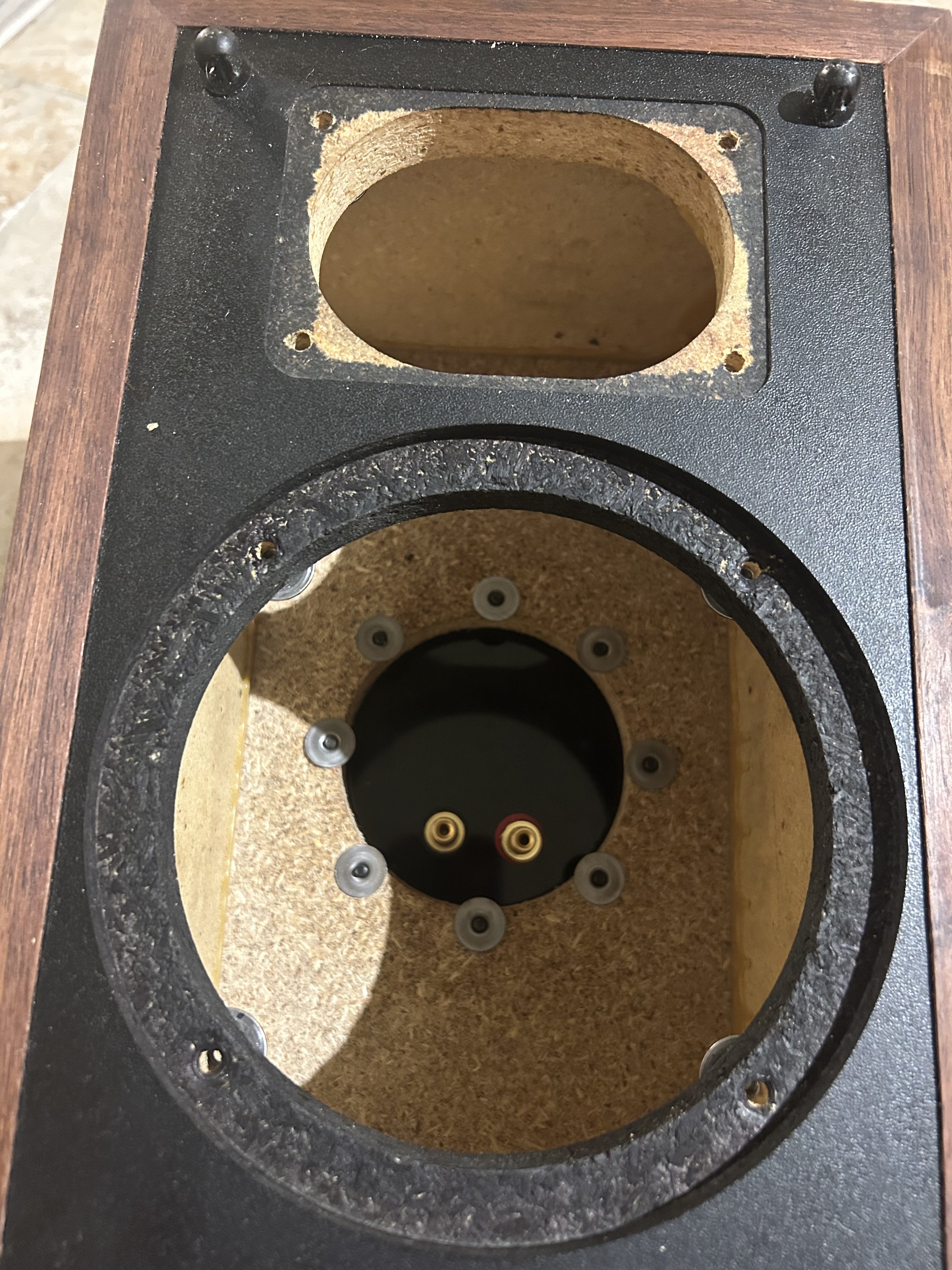
Another issue you have is that you used the same flange nuts on the speaker mounting holes and they extend into the circumference of the driver opening. I really hope that the driver baskets don't interfere with those flanges otherwise the day you cinch down on them is the day they will fail. If that flange impacts the driver basket, it will not only cause severely uneven clamping but it will also cause lateral forces that will pry that threaded sleeve right out of it's hole. If it does impact the best you can hope for is uneven seating of the driver causing air leakage and spoiling your enclosure tuning for your port tuning.
On top of that, the binding posts aren't level and canted with the negative terminal sitting higher than the positive terminal. The reason that is bad is because your pair of wires are going to have a stress point where they break over and drop straight down. That will cause them to eventually wear and loosen over time. Especially as they heat up and cool down. If you're going to use banana plugs or standoffs, then you should make sure that they aren't close enough to short, both outside the enclosure and inside. I mean, that's the reason binding posts are separated to begin with.
But, it's too late now so I'll pray for your sustained success with this methodology.
So flag me all you want, I'm not being a jerk here. I'm pointing out glaring issues with this "build" while being insulted for it at every turn. Contrary to popular belief, I do know what I am talking about here.
I have built competition winning subwoofer enclosures of all kinds. They have far higher stresses on them than a mere Monitor 4 enclosure. I have yet to have one fail or not perform to or exceed what minimum specification they were designed to. So I'm good on the "learning" part as there's nothing ground-breaking here. There's some stuff being tried that I know doesn't work. Some from experience some from knowledge based on learning, myself. But hey, what do I know? I'm just supposed to keep my mouth shut and watch people fail emphatically because of "feelings" or some BS like that when I could have easily helped them out if they were willing to listen instead of fight with me and insult me.Expert Moron Extraordinaire
You're just jealous 'cause the voices don't talk to you! -
For those who don't know what tee-nuts are, they are these:
In the interest of accuracy -- in your image only the one on the right is a T-nut -- the other is a threaded insert -- the OP appears to be using neither of these -- they appear to be hurricane nuts. -
slow_polk7 wrote: »
In the interest of accuracy -- in your image only the one on the right is a T-nut -- the other is a threaded insert -- the OP appears to be using neither of these -- they appear to be hurricane nuts.
Zooming in, I could swear I saw lines indicating there are teeth/spikes on the flanges.
Hurricane nuts aren't any better because they have even less stabilization capability than the other two and are more likely to tear loose, strip out the hole and create a situation where you can't get proper torque on the fastener to get proper clamping force on the gasket material and it can create a situation where the drivers will have to be removed to get a tool inside to immobilize the stripped hurricane nut to facilitate disassembly.
In the interest of accuracy, this is a Hurricane Nut.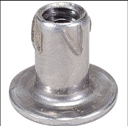
Additionally, "threaded insert" may be the technically accurate name but I have seen them also referred to as "tee nuts" and tee nuts referred to as threaded inserts or sleeves. I was merely trying to cover what I have see as "common vernacular" which is often inaccurate due to the inexperience of your average joe.
At the same time, I have also seen these sold as "tee nuts" and they are not "tee nuts".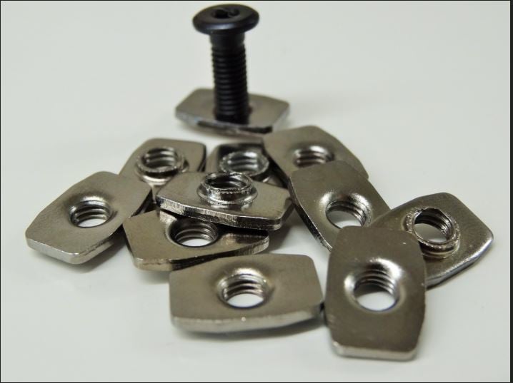
They are often call cam nuts which is also inaccurate but I have also seen them called track nuts which is more accurate but not obvious of their intended purpose without seeing them in a tracked mounting system.
Forgive my inaccuracy for trying to cover some bases for those who are not as experienced as you and do not understand what they are looking at in the poor photography provided without over-complicating things surrounding specialty fasteners and their uses.
Expert Moron Extraordinaire
You're just jealous 'cause the voices don't talk to you!