PSW 110 Service Manual or Schematics
Comments
-
Hello,
See if you get it now.. -
Hello!! I am tring to repair my SUB - PSV 111.
Need Schematics.Post edited by TeeKriss on -
Post edited by SeleniumFalcon on
-
Big mistake posting your email addy on a public forum.Political Correctness'.........defined
"A doctrine fostered by a delusional, illogical minority and rabidly promoted by an unscrupulous mainstream media, which holds forth the proposition that it is entirely possible to pick up a t-u-r-d by the clean end."
President of Club Polk -
I've replaced almost all the capacitors, but the problem is still there. We really need a circuit for troubleshooting.
PSW 111 v2 230v.
-
Schematic sent..
-
I've replaced almost all the capacitors, but the problem is still there. We really need a circuit for troubleshooting.
PSW 111 v2 230v.
The defect is the heartbeat? Are you able to check if the dual voltage regulators for the pre/filter stage are working well?
-
Hello!!
The problem with my subwoofer was that from time to time it seemed to stop sounding, but not completely, but it did not work as usual. I can't really explain exactly how it was.
Yes, well, I'll try to check the dual regulators. -
SeleniumFalcon wrote: »Schematic sent..
Got it!! Thank you so Much!! -
You're welcome, good luck with the repair!
-
Hello!!
The problem with my subwoofer was that from time to time it seemed to stop sounding, but not completely, but it did not work as usual. I can't really explain exactly how it was.
Yes, well, I'll try to check the dual regulators.
The defect for which the capacitors and/or their voltage regulators, which then power the op-amps, are suspected is the heartbeat, it is a self-oscillation of the circuit. If the defect that your sub has is different, the problem may be elsewhere.
-
Hello! If you have the schematic/diagram/service manual for the Polkaudio PSW111, could you please email me a copy? Thanks.
-
Hi.
Im looking for the service manual or schematic diagram for PSW111 also. Please send me a copy.
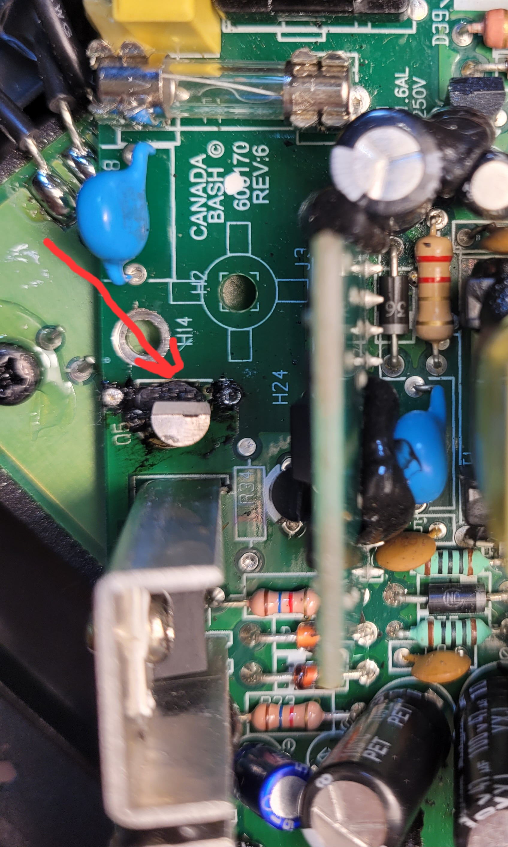
After replace some Ecap. The resistor that near Q5 was burned after 1-2mins normal running. The R34 seems got high temperature also. I'm trying to fix it. Thank you.. -
Add photo
-
bao19922002 wrote: »Hi.
Im looking for the service manual or schematic diagram for PSW111 also. Please send me a copy.
After replace some Ecap. The resistor that near Q5 was burned after 1-2mins normal running. The R34 seems got high temperature also. I'm trying to fix it. Thank you..
I just send it in your inbox.
The part of the circuit with Q5 and R34 is for stabilize the virtual ground at the halfway up the voltage for the final power transistors. A single supply switching voltage comes from one of the secondary of the transformer after D1 and the filtering of Ecap C14, after Q4,Q5,R34,R35 end other components split the voltage. There is something that unbalancing the circuit
What was the problem before recap?Post edited by Fabio_rm on -
.. A single supply switching voltage comes from one of the secondary of the transformer after D1 and the filtering of Ecap C14, after Q4,Q5,R34,R35 end other components split the voltage. There is something that unbalancing the circuit...
First static split is operate by 2 watt power resistors R24 - R25, dinamic stabilzed after by Q4 and Q5
Be careful that the supply voltage varies depending on the amplitude of the signal, using a feedback, this is the BASH amplifier patent to increase efficiency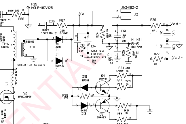
-
bao19922002 wrote: »Hi.
Im looking for the service manual or schematic diagram for PSW111 also. Please send me a copy.
After replace some Ecap. The resistor that near Q5 was burned after 1-2mins normal running. The R34 seems got high temperature also. I'm trying to fix it. Thank you..
I just send it in your inbox.
The part of the circuit with Q5 and R34 is for stabilize the virtual ground at the halfway up the voltage for the final power transistors. A single supply switching voltage comes from one of the secondary of the transformer after D1 and the filtering of Ecap C14, after Q4,Q5,R34,R35 end other components split the voltage. There is something that unbalancing the circuit
What was the problem before recap?
Before recap, only the indicator on but not working, also had little pop noise came out from spk at all mode(On/Auto/Stby).
After recap, pop noise gone and working properly, but Unfortunately the resistor smoke and born after 1-2mins. -
bao19922002 wrote: »Before recap, only the indicator on but not working, also had little pop noise came out from spk at all mode(On/Auto/Stby).
After recap, pop noise gone and working properly, but Unfortunately the resistor smoke and born after 1-2mins.
did you also change the 120uF Ecap c14?
-
bao19922002 wrote: »Before recap, only the indicator on but not working, also had little pop noise came out from spk at all mode(On/Auto/Stby).
After recap, pop noise gone and working properly, but Unfortunately the resistor smoke and born after 1-2mins.
did you also change the 120uF Ecap c14?
C14 wasn't replaced.
Today, I checked the components near Q4/Q5, including D10/D13, and found no problems. So, I replaced R34/R35, and it works normally. I've been running test for 3 hours, and everything is normal. It's strange that the resistor was overheating and smoking before. -
bao19922002 wrote: »C14 wasn't replaced.
Today, I checked the components near Q4/Q5, including D10/D13, and found no problems. So, I replaced R34/R35, and it works normally. I've been running test for 3 hours, and everything is normal. It's strange that the resistor was overheating and smoking before.
I don't know what to say, perhaps there was a faulty solder; desoldering and soldering the components restored the faulty solder. We'll never know for sure; all you can do is hope the problem is solved for good and doesn't happen again.
-
Some of these boards are covered in a type of glue that becomes conductive as it ages. Maybe the removal of the glue to get to the problem you inadvertently solved both problems unknowingly.
-
Hi. I am working on a Polk Sub-Woofer. The board is PSW110V2 110V.
Diode D1 (MUR420) shorted. I replaced that but output is oscillating.
Not getting any further without a schematic. Could I get it sent to me?
Thanks & regards. -
Schematic sent..
-
Could someone provide the value/specs for the ceramic disc cap C8?
-
There are two possible variations of the PSW110 amplifier with two schematic drawings. I found a C8, on one of the schematics, connected in series with R75 (100 ohm) which is 100pF rated at 1kV.
-
SeleniumFalcon wrote: »There are two possible variations of the PSW110 amplifier with two schematic drawings. I found a C8, on one of the schematics, connected in series with R75 (100 ohm) which is 100pF rated at 1kV.
Thanks! -
You're welcome, good luck with your project!
-
Hello everyone!
I'm trying to fix the issue with a very distorted sound especially in auto mode. The led color is looks strange as well - white and orange. Could anyone please share a schematic diagram for PSW110 if possible? It seems like the issue is with the control board. Thank you in advancePost edited by SeleniumFalcon on -
Schematics sent...
-
Hello, I would appreciate it if you could email me the polk audio psw110 schematics.