Cardas Internal Wire Upgrade For The SDA CRS+ (1989 Version)

DarqueKnight
Posts: 6,765
Introduction
I did. It went very well. I did not precondition the wire on the Audiodharma Cable Cooker this time. I wanted to hear what the wire sounded like in its "unbroken in" state. The retail cost of the wire was $218. The retail cost of the connectors was $146. I received a 20% discount on the wire and a 50% discount on the connectors, for a total material cost of $247. The total time invested, inclusive of 3 hours of listening evaluations, was 24 hours. Only 7 hours were spent in cable fabrication and wire replacement. The rest of the time was spent in disassembly, assembly, measurement, documentation, cleanup, and listening.
This was my fourth exercise replacing stock internal speaker wire with Cardas wire. Prior modifications were: 1. SDA SRS 1.2 TL, 2. SDA SRS, 3. LSi9.
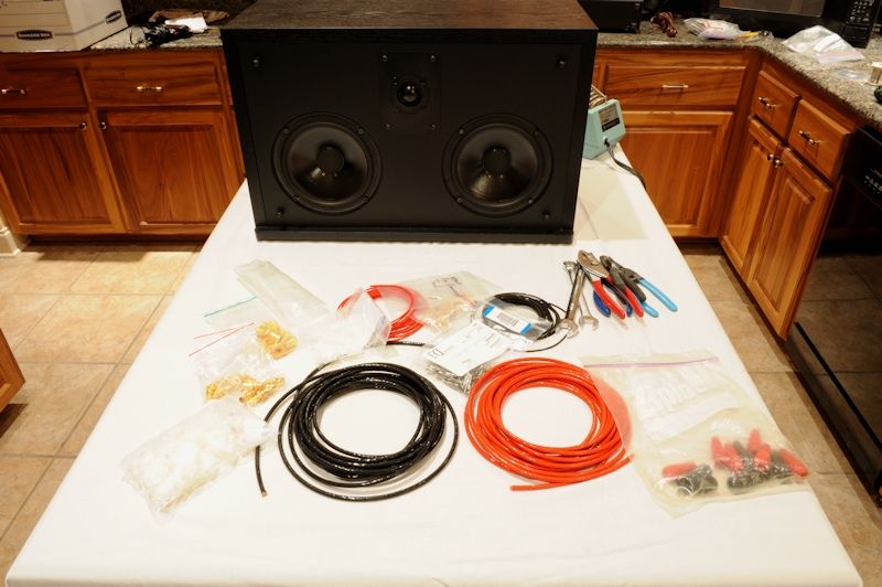
Figure 1. One of my black oak CRS+s being prepped for surgery.
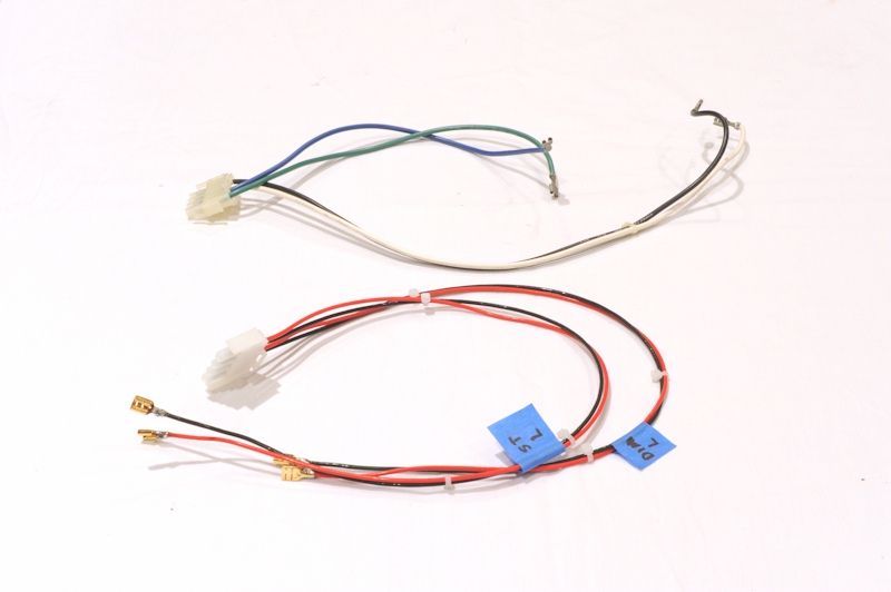
Figure 2. Stock driver wiring harness above its Cardas replacement. The Cardas wire is slightly larger gauge,
but appears smaller because it has thinner insulation.
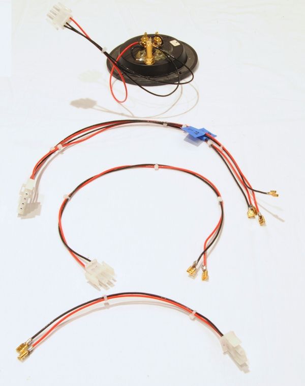
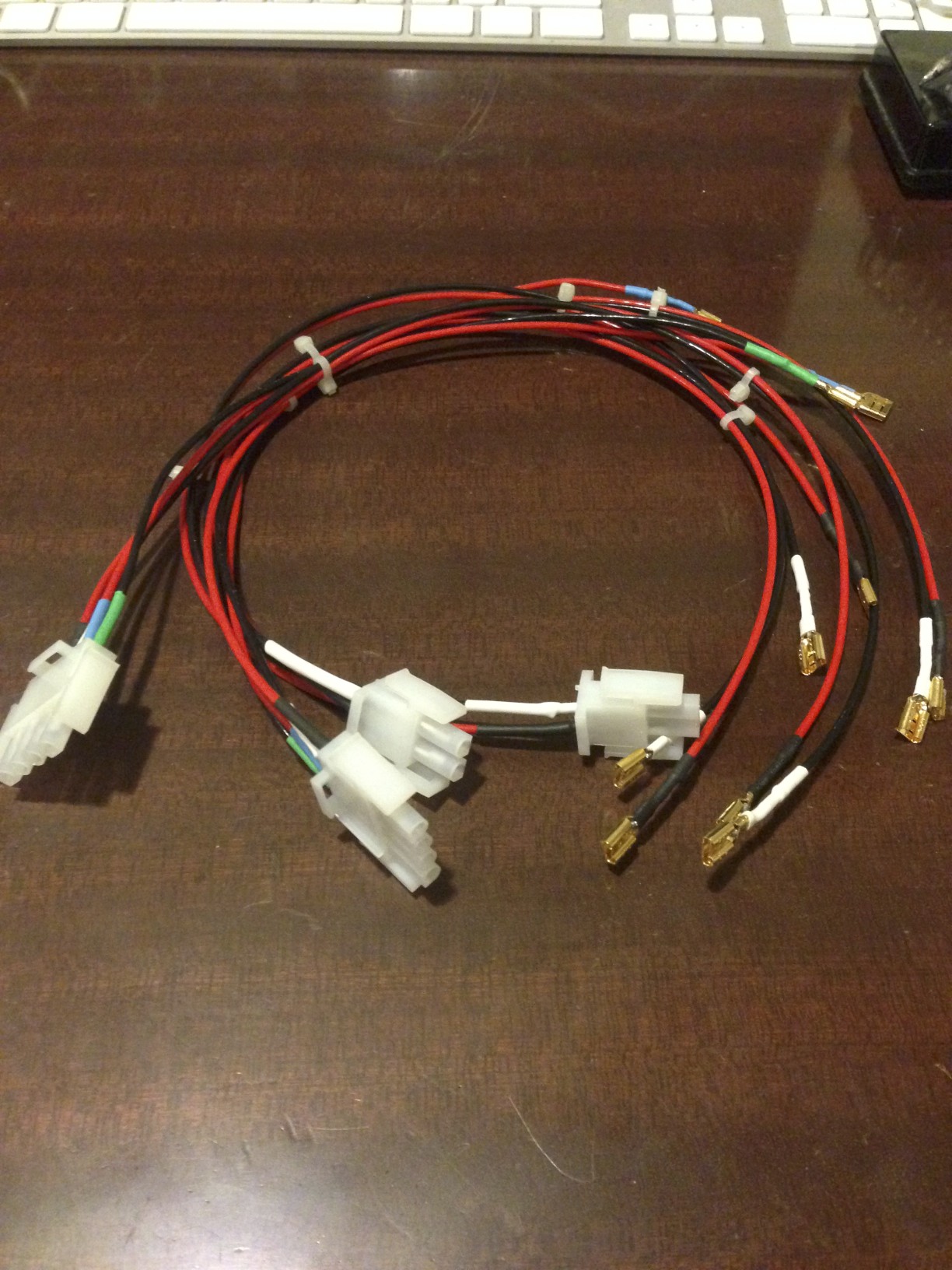
Figure 3. Cardas wiring harnesses, top to bottom: binding posts, drivers, tweeter, SDA inductor.

Figure 4. AI-1 Dreadnought non-common ground interface and Cardas 9.5 AWG cables, 10 feet in length.
The previous AI-1 cables were Monster Cable Z3 Reference speaker cables (10 AWG).
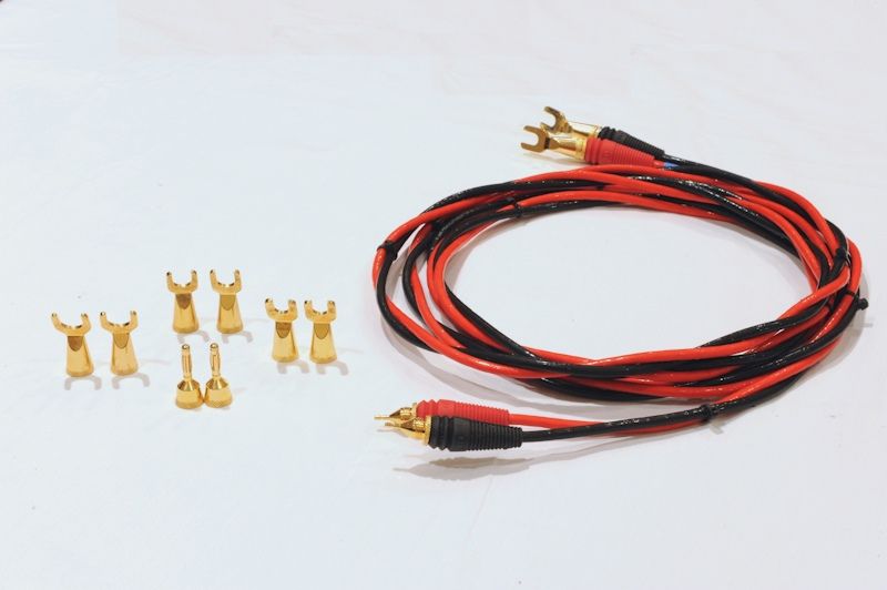
Figure 5. The Cardas AI-1 cables were terminated with Monster Lock pins, which provide the flexibility of
attaching bananas and different size spades.

Figure 6. Ready for reassembly.
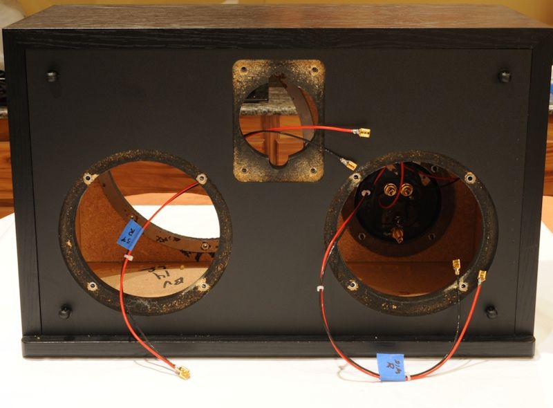
Figure 7. Ready for driver installation.
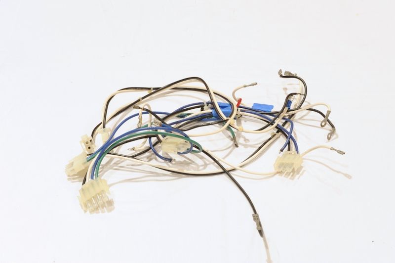
Figure 8. Stock wiring harnesses. Twenty-four years of service is long enough.
Assembly Notes
The obnoxious invisible enamel coating of each individual wire strand was first ground off with a Dremel carbon steel brush (part number 428) and the residual enamel was burned off with solder. The 9.5 AWG wire was particularly difficult to work with. A solder pot would have made things a lot easier, but I didn't want to have to buy a ton of Cardas bar solder, most of which I would not use, and I didn't want to invest in a solder pot since the one I wanted cost over $100 (American Beauty MP-9) and would see very limited use.
It is not a good idea to use the Cardas strand solder in solder pots because it contains rosin, which will cause a lot of smoke and will form a mess by bubbling up and forming a layer on top of the solder.
Resistance measurements were taken after soldering to make sure a high resistance connection was not made. A high resistance compared to the stock wire would have indicated that some wire strands were not coated with solder.
The DC resistance of the totally stock speakers was 3.94 ohms (L) and 3.82 ohms (R).
The DC resistance after the Solen SDA inductor modification was 2.81 ohms (L) and 2.85 ohms (R).
The DC resistance after the Sonicap/Jantzen inductor modification was 3.38 ohms (L) and 3.38 ohms (R).
Listening Evaluations
The CRS+s were auditioned in my home theater system with the following electronics and cables:
Pioneer BDP-09FD Bluray Disc Player,
Sony TA-P9000ES Preamplifier,
Adcom GFA-5500 Power Amplifier (350 watts into 4 ohms),
PS Audio P10 AC Regenerator for preamp and Bluray player,
Monster Cable Z100i Interconnects,
Monster Cable Z2 Reference Speaker Cable,
PS Audio AC 5 and Statement SC Power Cords.
These SDA CRS+s are used in my system at work, which consists of the following:
Nakamichi CA 5A II Preamplifier,
Yamaha TX-1000U Digital Tuner,
Yamaha CDX-1110U CD Player,
Adcom GFA-555 Mk II Power Amplifier (350 watts into 4 ohms),
Signal Cable Analog 2 Interconnects,
Signal Cable MagicPower Cords,
Monster Cable Z2 Reference Speaker Cables.

Figure 9. Such Good Sound!
Two 21st-Century classical music selections were used in listening evaluations:
"Antissa" - from the "Unearthed" CD by E. S. Posthumus.
"Selisona Pi", from the "Cartographer" CD by E. S. Posthumus.
Both selections are well recorded and feature a wide and deep sound stage, thunderous bass, soaring highs, vocals, choir, and lush percussion.
The pre-rewired speakers were auditioned and documented with spatial maps and detailed listening notes, then the left speaker was rewired and compared to the right, then both rewired speakers were auditioned with the Monster Cable Z3 AI-1 cables and then with the Cardas 9.5 AWG AI-1 cables. The stock-wired right speaker sounded lower in volume and veiled compared to the left speaker with Cardas wire. When both speakers were wired with Cardas, there was a striking improvement in clarity, sustain, decay, detail and depth, with more defined layering and front to back distance between images. The center image was thicker, and there was overall more tactile sensation. There was no change in lateral placement of images. The choir image on both music selections was about 1 foot higher after the rewire. I particularly appreciated the increase in low level detail since I use these speakers at work and usually have to play at low volume.
Compared to the Monster Z3 AI-1 cables, the Cardas cables provided a little more clarity and detail in the center and a moderate increase in clarity and detail at the sides and rear of the sound stage. I was hoping there would be little to no difference, because I did not want to deal with that thick Cardas wire again when rewiring my other two CRS+ pairs, plus, I could save a few bucks. Unfortunately, my fabrication and financial biases were overruled by my ears.
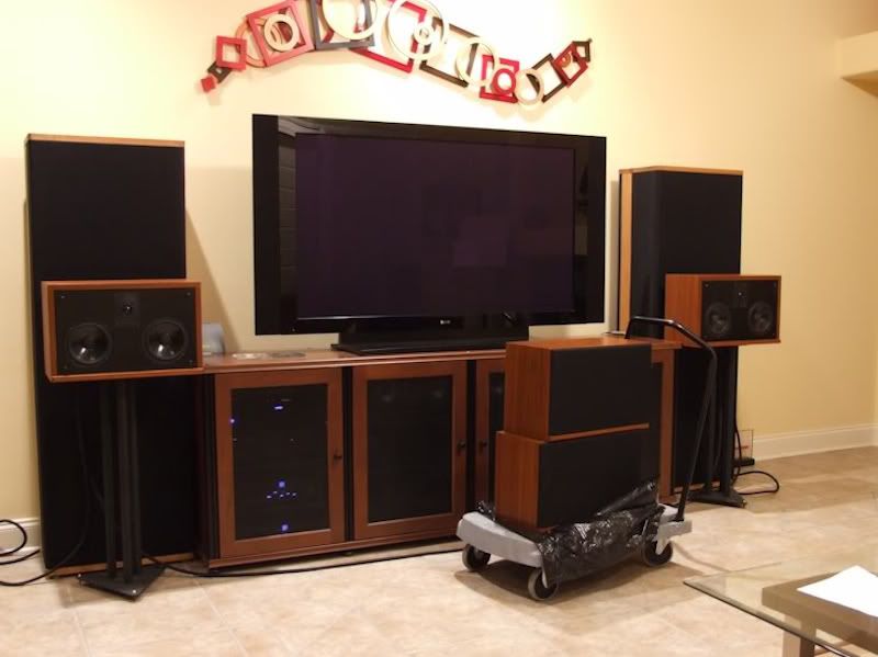
Figure 10. In the future, when I am more dedicated to audio than I am now, I will rewire my other two pairs
of CRS+s with Cardas.
References
Cardas Wire Replacement for the SDA SRS 1.2 TL
Cardas Wire Replacement for the SDA SRS and LSi9
Ray, did you ever end up re-wiring your CRS+'s with the Cardas wire? Wondering how it went?
I did. It went very well. I did not precondition the wire on the Audiodharma Cable Cooker this time. I wanted to hear what the wire sounded like in its "unbroken in" state. The retail cost of the wire was $218. The retail cost of the connectors was $146. I received a 20% discount on the wire and a 50% discount on the connectors, for a total material cost of $247. The total time invested, inclusive of 3 hours of listening evaluations, was 24 hours. Only 7 hours were spent in cable fabrication and wire replacement. The rest of the time was spent in disassembly, assembly, measurement, documentation, cleanup, and listening.
This was my fourth exercise replacing stock internal speaker wire with Cardas wire. Prior modifications were: 1. SDA SRS 1.2 TL, 2. SDA SRS, 3. LSi9.
Figure 1. One of my black oak CRS+s being prepped for surgery.
Figure 2. Stock driver wiring harness above its Cardas replacement. The Cardas wire is slightly larger gauge,
but appears smaller because it has thinner insulation.
Figure 3. Cardas wiring harnesses, top to bottom: binding posts, drivers, tweeter, SDA inductor.
Figure 4. AI-1 Dreadnought non-common ground interface and Cardas 9.5 AWG cables, 10 feet in length.
The previous AI-1 cables were Monster Cable Z3 Reference speaker cables (10 AWG).
Figure 5. The Cardas AI-1 cables were terminated with Monster Lock pins, which provide the flexibility of
attaching bananas and different size spades.
Figure 6. Ready for reassembly.
Figure 7. Ready for driver installation.
Figure 8. Stock wiring harnesses. Twenty-four years of service is long enough.
Assembly Notes
The obnoxious invisible enamel coating of each individual wire strand was first ground off with a Dremel carbon steel brush (part number 428) and the residual enamel was burned off with solder. The 9.5 AWG wire was particularly difficult to work with. A solder pot would have made things a lot easier, but I didn't want to have to buy a ton of Cardas bar solder, most of which I would not use, and I didn't want to invest in a solder pot since the one I wanted cost over $100 (American Beauty MP-9) and would see very limited use.
It is not a good idea to use the Cardas strand solder in solder pots because it contains rosin, which will cause a lot of smoke and will form a mess by bubbling up and forming a layer on top of the solder.
Resistance measurements were taken after soldering to make sure a high resistance connection was not made. A high resistance compared to the stock wire would have indicated that some wire strands were not coated with solder.
Table 1
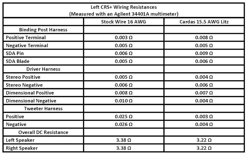
The DC resistance of the totally stock speakers was 3.94 ohms (L) and 3.82 ohms (R).
The DC resistance after the Solen SDA inductor modification was 2.81 ohms (L) and 2.85 ohms (R).
The DC resistance after the Sonicap/Jantzen inductor modification was 3.38 ohms (L) and 3.38 ohms (R).
Listening Evaluations
The CRS+s were auditioned in my home theater system with the following electronics and cables:
Pioneer BDP-09FD Bluray Disc Player,
Sony TA-P9000ES Preamplifier,
Adcom GFA-5500 Power Amplifier (350 watts into 4 ohms),
PS Audio P10 AC Regenerator for preamp and Bluray player,
Monster Cable Z100i Interconnects,
Monster Cable Z2 Reference Speaker Cable,
PS Audio AC 5 and Statement SC Power Cords.
These SDA CRS+s are used in my system at work, which consists of the following:
Nakamichi CA 5A II Preamplifier,
Yamaha TX-1000U Digital Tuner,
Yamaha CDX-1110U CD Player,
Adcom GFA-555 Mk II Power Amplifier (350 watts into 4 ohms),
Signal Cable Analog 2 Interconnects,
Signal Cable MagicPower Cords,
Monster Cable Z2 Reference Speaker Cables.
Figure 9. Such Good Sound!
Two 21st-Century classical music selections were used in listening evaluations:
"Antissa" - from the "Unearthed" CD by E. S. Posthumus.
"Selisona Pi", from the "Cartographer" CD by E. S. Posthumus.
Both selections are well recorded and feature a wide and deep sound stage, thunderous bass, soaring highs, vocals, choir, and lush percussion.
The pre-rewired speakers were auditioned and documented with spatial maps and detailed listening notes, then the left speaker was rewired and compared to the right, then both rewired speakers were auditioned with the Monster Cable Z3 AI-1 cables and then with the Cardas 9.5 AWG AI-1 cables. The stock-wired right speaker sounded lower in volume and veiled compared to the left speaker with Cardas wire. When both speakers were wired with Cardas, there was a striking improvement in clarity, sustain, decay, detail and depth, with more defined layering and front to back distance between images. The center image was thicker, and there was overall more tactile sensation. There was no change in lateral placement of images. The choir image on both music selections was about 1 foot higher after the rewire. I particularly appreciated the increase in low level detail since I use these speakers at work and usually have to play at low volume.
Compared to the Monster Z3 AI-1 cables, the Cardas cables provided a little more clarity and detail in the center and a moderate increase in clarity and detail at the sides and rear of the sound stage. I was hoping there would be little to no difference, because I did not want to deal with that thick Cardas wire again when rewiring my other two CRS+ pairs, plus, I could save a few bucks. Unfortunately, my fabrication and financial biases were overruled by my ears.
Figure 10. In the future, when I am more dedicated to audio than I am now, I will rewire my other two pairs
of CRS+s with Cardas.
References
Cardas Wire Replacement for the SDA SRS 1.2 TL
Cardas Wire Replacement for the SDA SRS and LSi9
Proud and loyal citizen of the Digital Domain and Solid State Country!
Post edited by DarqueKnight on
Comments
-
Raif, I love reading about your mods and reviews, although it always seems too cost me money! Great job!Home Theater
Onkyo PR-SC5508 Sharp LC-70LE847U
Emotiva XPA-5 Emotiva XPA-2 Emotiva UPA-2
Front RTi-A9 Wide RTi-A7 Center CSi-A6 Surround FXi-A6 Rear RTi-A3 Sub 2x PSW505
Sony BDP-S790 Dishnetwork Hopper/Joey Logitech Harmony One Apple TV
Two Channel
Oppo 105D BAT VK-500 w/BatPack SDA SRS 2.3 Dreadnought Squeezebox Touch Apple TV -
Nice job! I will be doing my project in the next few weeks. I ended up getting an entry level solder pot, imported from China, and Kester bar solder, to keep the costs under control. In addition to tinning the Cardas Litz with it, I am going to tin the ends of my Solen 16mH inductor with it, as I suspect I can get a better contact than scraping the insulation as I'd done previously. Unfortunately, my gear is all packed up pending some home repairs prior to putting my house on the market, so won't be auditioning these improvements for some time, but at least they will be ready to go when I set up shop in the next abode. Btw I like the fact that you have a Molex connector for your SDA inductor, I have two leads soldered to the board.Good music, a good source, and good power can make SDA's sing. Tubes make them dance.
-
Btw, aren't you muddying your listening tests having the rear-firing PRs of the CRS+'s pointing straight into the drivers of your big boys?Good music, a good source, and good power can make SDA's sing. Tubes make them dance.
-
There is actually an enhanced sense of depth with the CRS+s being in front of a "pseudo wall" made by the SRSs, which is 18 inches further out from the rear wall. Optimal setup would be taking the SRS's out of the room and placing the CRS+s close to the rear wall. I got better bass performance when I did that in past trials. I didn't hear any muddying of the sound with the SRSs being behind the CRS+s.Btw, aren't you muddying your listening tests having the rear-firing PRs of the CRS+'s pointing straight into the drivers of your big boys?
The passive radiator covers the rear half of the cabinet directly behind the CRS+'s own stereo driver. As the CRS+s are positioned in the pictures, their passive radiators are directly in front of the SRS's lowermost stereo driver. I expect that the speaker stands have more effect on the sound than the SRS's behind them. Notice that in figure 10, each CRS+ is on a single stand. In figure 9, each CRS+ is on two stands butted together. I heard an improvement in clarity and detail with the two-stand-per-speaker arrangement.Proud and loyal citizen of the Digital Domain and Solid State Country! -
I'm thinking of using some little strips of colored shirink tubing on either end of each cable I create in white, blue, green, and black as indicators of what the stock wiring color scheme was. The molex connectors make it pretty idiot proof. but being able to visualize the blue/green pairs in terms of the stock color scheme is handy when following the schematics.Good music, a good source, and good power can make SDA's sing. Tubes make them dance.
-
Also, I'm thinking of using the solder pot on the Cardas binding posts. I'd like to tin the connector for a few seconds in the pot, then it should be a breeze to connect tinned wire to the tinned binding post.Good music, a good source, and good power can make SDA's sing. Tubes make them dance.
-
Just realizing that your molex connectors are gold. Nice touch. Got part numbers for those? The pin connectors on your crossover boards are gold as well?Good music, a good source, and good power can make SDA's sing. Tubes make them dance.
-
Just realizing that your molex connectors are gold. Nice touch. Got part numbers for those? The pin connectors on your crossover boards are gold as well?
The disconnects that plug onto the driver tabs are gold plated. The pins inside the Molex connectors are tinned brass. The disconnects are made by WBT (part number QD25). They were purchased from Madisound (75 cents each).Proud and loyal citizen of the Digital Domain and Solid State Country! -
Do you have the part numbers for the tinned brass Molex connectors?Good music, a good source, and good power can make SDA's sing. Tubes make them dance.
-
Do you have the part numbers for the tinned brass Molex connectors?
I am not sure whether you meant just the pin contacts themselves or the complete plastic housing, so I will provide part numbers for both. The plastic housings and pin contacts are bought separately.
The parts were purchased from Mouser (www.mouser.com)
Pin contact: 571-3505471
Four position plug housing: 571-14807020
Three position plug housing: 571-14807000
Two position plug housing: 571-14806980
AMP does make two gold plated brass pin contacts:
571-3505472 - entirely gold plated.
571-3505477 - select gold plated with gold only on part of pint that contacts socket.
The gold plated pin costs 94 cents each and the select gold pin costs 66 cents each compared to 10 cents for the tinned brass pin.Proud and loyal citizen of the Digital Domain and Solid State Country! -
Thanks for that. Just double checked, the ones I bought from Mouser are the tinned brass. Ok, I'm in business!Good music, a good source, and good power can make SDA's sing. Tubes make them dance.
-
Well look what I've got!!!


Here's a few pics of the solder pot: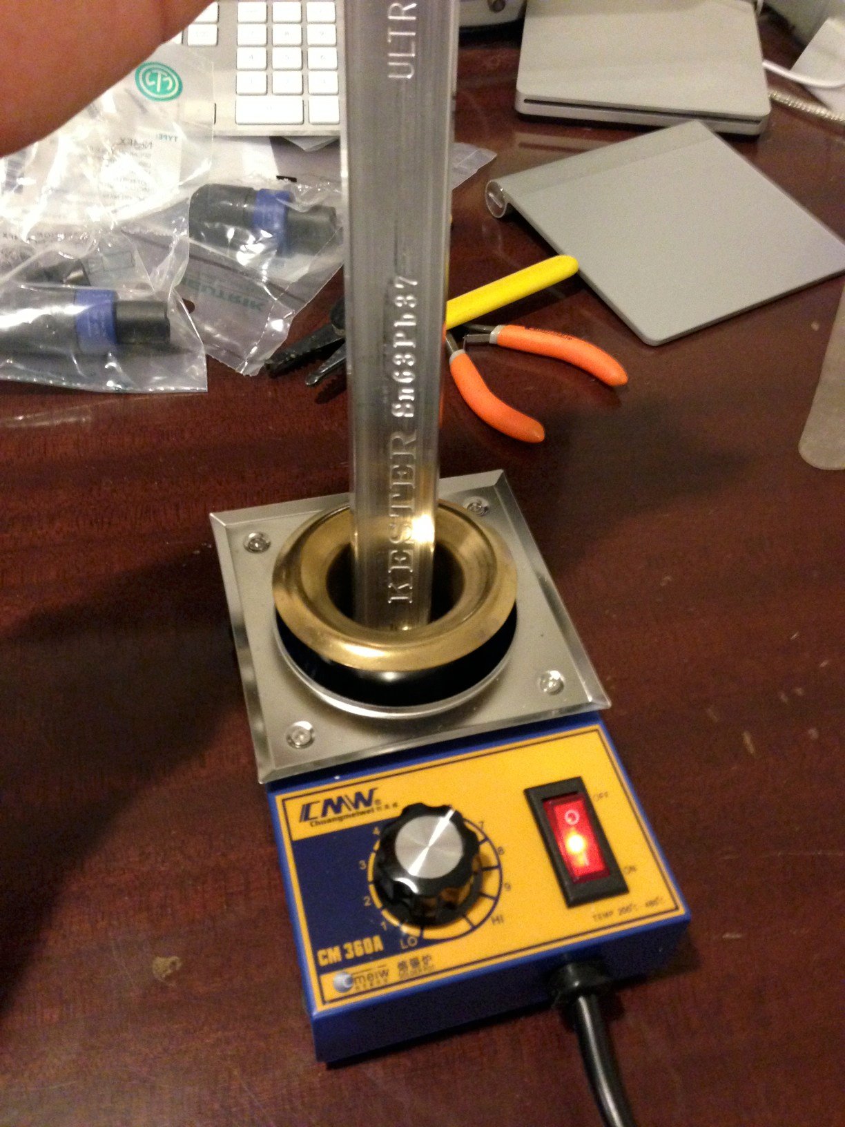

Raife, thank you once again for all the fantastic advice, now and all the times in the past!Good music, a good source, and good power can make SDA's sing. Tubes make them dance. -
Looks good. You should start up a custom Cardas cable fabrication business.Proud and loyal citizen of the Digital Domain and Solid State Country!
-
Hah! Something tells me I shouldn't go quitting my day job just yet.
The solder pot is a great tool. Any time I need to tin a wire from now on, it's getting plugged in.Good music, a good source, and good power can make SDA's sing. Tubes make them dance. -
The solder pot is a great tool. Any time I need to tin a wire from now on, it's getting plugged in.
When I am ready to rewire my other two sets of CRS+s, I will get the American Beauty MP-9 solder pot.Proud and loyal citizen of the Digital Domain and Solid State Country! -
Or I could just loan you mine.Good music, a good source, and good power can make SDA's sing. Tubes make them dance.
-
Or I could just loan you mine.
Thanks for the generous offer, but I decided to go ahead and get the MP-9 solder pot now because I wanted to redo the CRS+'s AI-1 cables.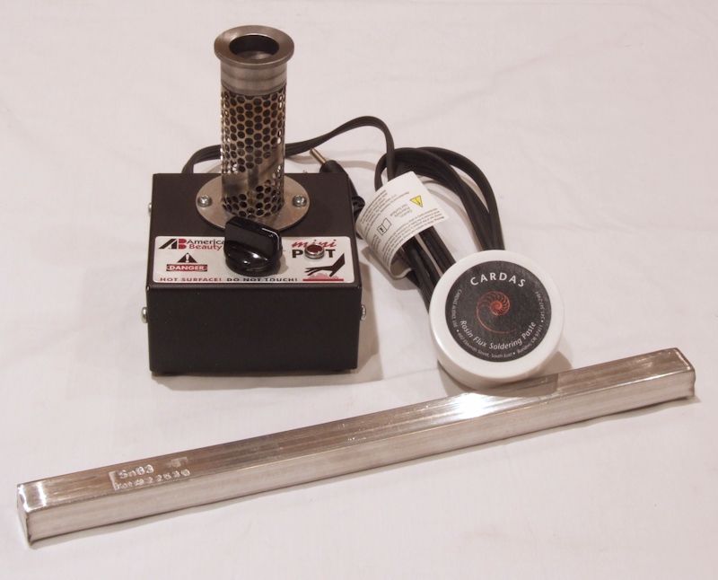
Figure 11. A good solder pot makes short work of dealing with Cardas wire. This amount of bar solder should
last the rest of my life.
The Cardas bar solder and Cardas soldering paste (flux) were purchased from Parts Connexion (www.partsconnexion.com).
The grinding wheel and soldering wand method for removing the wire enamel works very well with Cardas small gauge wire. In most cases, the resistances of the Cardas 15.5 AWG wire segments were close to the theoretical reference values for 15.5 AWG copper wire: 0.004 ohm for the 13" segments and 0.006 ohm for the 20" segments (table 2).
Cardas 9.5 AWG litz wire was used to make replacement cables for the AI-1 Dreadnought. With the grinding and wand soldering method, the much thicker and more tightly wound Cardas 9.5 AWG wire segment resistances were far from the theoretical reference values for a 10 foot length (table 3). The reference resistance value for a 10 foot length of 15.5 AWG copper wire is 0.009 ohm. The resistances for the ground and wand soldered segments were three to four times greater.
The solder pot was set to the maximum temperature (there are no temperature markings around the dial). After 15 minutes, I used a Fluke model 561 infrared thermometer, aimed at the base of the solder pot's crucible, to measure the solder pot's temperature. The temperature was 560 degrees F, which was 200 degrees above the solder's melting point. Setting the MP-9's temperature below maximum did not work very well with the Cardas wire, as it took a very long time, 30 seconds or more, to tin the wire. After the 9.5 AWG cable terminations were removed, the wires were spread out a little, then dipped in solder paste, then dipped in the solder bath for three 10 second intervals. A trial run with a 1.25 foot scrap piece of Cardas 9.5 AWG indicated that three dips was required to get all the enamel off the wires. One ten second dip was sufficient to remove all the enamel from the 15.5 AWG wire.Table 2.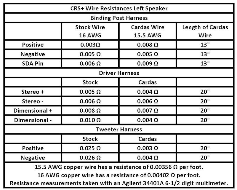
Table 3.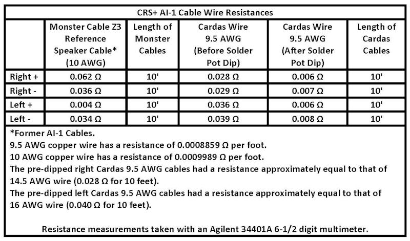
The MP-9 came with a fine manual, which included this helpful bit of information:
"When a new solder pot is first put into service the amount of dross production can be significant, especially during the initial start-up period. This is a temporary condition that occurs while the tin in the solder allow is interacting with the grey cast iron, forming a tin/ferrite barrier on the surface of the crucible. The formation of this barrier improves the solder pot's efficiency, protects the crucible from the solution action of the tin and helps to **** dross production in the future. It takes about 72 hours of operation for the protective barrier to form, and the dross production to lessen. Once this barrier has formed on the walls of the crucible it will remain there unless it is disturbed or damaged with a scraper or a similar type of tool."Proud and loyal citizen of the Digital Domain and Solid State Country! -
Nice! Mine is definitely coming out any time I need to tin anything.Good music, a good source, and good power can make SDA's sing. Tubes make them dance.

