Diagonal Wiring Experiments With The SDA SRS 1.2TL

DarqueKnight
Posts: 6,765
Introduction
Nordost, a manufacturer of fine, high performance audio cables, wrote a tutorial on various methods of connecting single run speaker cables to bi-wirable speakers. A copy of the tutorial is attached. The tutorial claims:
"Often, the very best results are achieved using a diagonal connection. This involves connecting the red cable to the bass/mid terminal and the black to the treble, with the jumpers arranged accordingly, bass to treble on the red (or +ve) side of the crossover, treble to bass on the black (or -ve) side. This is slightly more confusing to wire, however, with a little extra care and patience the results can be well worthwhile, and once you are familiar with bi-wiring procedures this often becomes the new default set up, offering greater air, transparency, dimensionality and subtlety."/"
Previously, I had found, per Polk's recommendation, that my SDA SRS 1.2TLs sounded best with single run speaker cable when the cable was connected to the low frequency binding posts and jumpered up to the high frequency posts. Connecting the speaker cable to the high frequency posts and jumpering down to the low frequency post resulted in a small loss of clarity, detail, and front to back inter-image spacing. These losses were most noticeable at the sides of the sound stage.
Connections
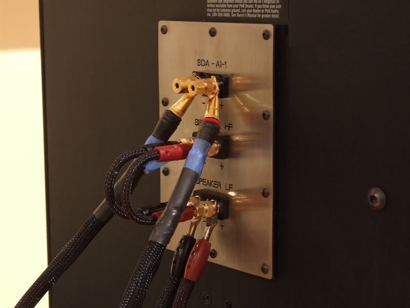
Figure 1. The SDA SRS 1.2TL's stock binding posts and plate were replaced with a custom plate and Cardas CCGR-S tellurium copper posts.
Since the photo above was taken, the Monster Cable Z2 Reference cables ($151/20 foot pair) for the Dreadnought A1-I Non Common Ground Interface have been replaced with PS Audio Xtream Resolution Reference cables ($800/3 meter pair). The AudioQuest Perfect Surface Copper jumpers ($189) have been replaced with AudioQuest Perfect Surface Silver jumpers ($429). The speaker cables are the same: AudioQuest Everest 72 Volt Dielectric Bias System ($11,700/8 foot pair).
Musical Selection
A single musical selection was used for these experiments: Ottmar Liebert's "Fireopal" (Acoustic Version) from his "Bare Wood 2002-2014" CD. The track has excellent recording quality in 88.2kHz resolution. This track is part of HDTracks.com's 2014 Sampler, which is available for free download. I liked this track so much that I listened to the whole album on Spotify, and then bought it.
Liebert says this about the album's compositions:
"Bare Wood is a compilation of pieces I created between 2002 and 2012. For this album I deleted all electric or electronic instruments from the original recordings and removed anything that was not Flamenco guitar or cajon. I then recorded additional Flamenco guitar parts and Jon Gagan recorded entirely new upright acoustic bass tracks for every piece. What emerged was the essence, the soul, the bare wood of the music."
Listening And Evaluation Methodology
The musical selection was listened to in both stereo and mono modes in various wiring configurations. Sketches were made of the positions of sound images and notes were made of the character of sound images.
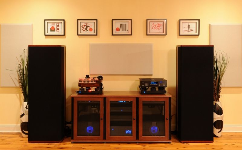
Figure 2. Two channel system.
Trial 1. Stereo mode with the speaker cables connected to the low frequency posts and jumpered up to the high frequency posts. This was the pre-experiment configuration.
Refer to figure 2 for the placement of sound images. The lead Flamenco guitar was in the exact center, just above the top of the equipment cabinet and two feet in front of the speaker plane. The upright acoustic bass was a foot to left of and three feet behind the lead flamenco guitar. The cajon (a small box-like drum) was just behind the speaker plane and between the turntable and the vertical center of the left speaker. A second Flamenco guitar was just behind the speaker plane and in the same space as the SACD player on the right.
There was a little more low frequency vibration coming through the left armrest, which was as expected since the drum and acoustic bass are arranged on the left of the sound stage.
Trial 2. Mono mode with the speaker cables connected to the low frequency posts and jumpered up to the high frequency posts.
There was equal tactile sensation from both armrests. All the sound images were clumped together in a large mass in the exact center of the sound stage, at the speaker plane, just above the top of the equipment cabinet.
Trial 3. Mono mode - diagonal wiring with the right speaker cable positive lead connected to the high frequency post and the negative lead connected to the low frequency post. Jumpers remained in place.
There was a shift of the center sound mass about six inches to the right. The right speaker sounded (apparently, but not measurably) louder and clearer. This was true when seated and when standing in turn 2 feet in front of each speaker. There was more vibration coming from the right armrest.
Trial 4. Stereo mode - diagonal wiring with the right speaker cable positive lead connected to the high frequency post and the negative lead connected to the low frequency post. Jumpers remained in place.
Same differences as in Trial 3 mono mode, but the difference was approximately halved.
Trial 5. Mono - diagonal wiring mode with the left speaker cable diagonally wired the same as the right: positive lead connected to the high frequency post and the negative lead connected to the low frequency post. Jumpers remained in place.
Center image mass moved to exact center. There was no difference in tactile sensation or sound level on either side of the sound stage. Bass was stronger compared to all previous trials.
Trial 6. Stereo mode - diagonal wiring with the left speaker cable diagonally wired the same as the right: positive lead connected to the high frequency post and the negative lead connected to the low frequency post. Jumpers remained in place.
Sound images moved back to the same positions as in Trial 1. The ambient echoes from the cajon on the left and second flamenco guitar on the right were louder and clearer. There was more weight and "wood sound" from the center flamenco guitar. There was more "string sound" and overtones from the acoustic bass. The sense of front to back space between images was enhanced.
Trial 7. Mono mode - diagonal wiring with the left speaker diagonally wired as in Trial 6 and the right speaker diagonally wired with the positive lead connected to the low frequency post and the negative lead connected to the high frequency post. Jumpers remained in place.
There was a shift of the center sound mass about six inches to the right. The right speaker sounded louder and clearer. This was true when seated and when standing in turn 2 feet in front of each speaker. There was more vibration coming from the right armrest.
Trial 8. Stereo mode - diagonal wiring with the left speaker cable diagonally wired the same as the right: positive lead connected to the low frequency post and the negative lead connected to the high frequency post. Jumpers remained in place.
Sound images moved back to the same positions as in Trial 1. Compared to Trial 6, the ambient echoes from the cajon on the left and second flamenco guitar on the right were louder and clearer. There was more weight and "wood sound" from the center flamenco guitar and cajon. There was more "string sound" and overtones from the acoustic bass. The sense of front to back space between images was enhanced.
Nordost, a manufacturer of fine, high performance audio cables, wrote a tutorial on various methods of connecting single run speaker cables to bi-wirable speakers. A copy of the tutorial is attached. The tutorial claims:
"Often, the very best results are achieved using a diagonal connection. This involves connecting the red cable to the bass/mid terminal and the black to the treble, with the jumpers arranged accordingly, bass to treble on the red (or +ve) side of the crossover, treble to bass on the black (or -ve) side. This is slightly more confusing to wire, however, with a little extra care and patience the results can be well worthwhile, and once you are familiar with bi-wiring procedures this often becomes the new default set up, offering greater air, transparency, dimensionality and subtlety."/"
Previously, I had found, per Polk's recommendation, that my SDA SRS 1.2TLs sounded best with single run speaker cable when the cable was connected to the low frequency binding posts and jumpered up to the high frequency posts. Connecting the speaker cable to the high frequency posts and jumpering down to the low frequency post resulted in a small loss of clarity, detail, and front to back inter-image spacing. These losses were most noticeable at the sides of the sound stage.
Connections

Figure 1. The SDA SRS 1.2TL's stock binding posts and plate were replaced with a custom plate and Cardas CCGR-S tellurium copper posts.
Since the photo above was taken, the Monster Cable Z2 Reference cables ($151/20 foot pair) for the Dreadnought A1-I Non Common Ground Interface have been replaced with PS Audio Xtream Resolution Reference cables ($800/3 meter pair). The AudioQuest Perfect Surface Copper jumpers ($189) have been replaced with AudioQuest Perfect Surface Silver jumpers ($429). The speaker cables are the same: AudioQuest Everest 72 Volt Dielectric Bias System ($11,700/8 foot pair).
Musical Selection
A single musical selection was used for these experiments: Ottmar Liebert's "Fireopal" (Acoustic Version) from his "Bare Wood 2002-2014" CD. The track has excellent recording quality in 88.2kHz resolution. This track is part of HDTracks.com's 2014 Sampler, which is available for free download. I liked this track so much that I listened to the whole album on Spotify, and then bought it.
Liebert says this about the album's compositions:
"Bare Wood is a compilation of pieces I created between 2002 and 2012. For this album I deleted all electric or electronic instruments from the original recordings and removed anything that was not Flamenco guitar or cajon. I then recorded additional Flamenco guitar parts and Jon Gagan recorded entirely new upright acoustic bass tracks for every piece. What emerged was the essence, the soul, the bare wood of the music."
Listening And Evaluation Methodology
The musical selection was listened to in both stereo and mono modes in various wiring configurations. Sketches were made of the positions of sound images and notes were made of the character of sound images.

Figure 2. Two channel system.
Trial 1. Stereo mode with the speaker cables connected to the low frequency posts and jumpered up to the high frequency posts. This was the pre-experiment configuration.
Refer to figure 2 for the placement of sound images. The lead Flamenco guitar was in the exact center, just above the top of the equipment cabinet and two feet in front of the speaker plane. The upright acoustic bass was a foot to left of and three feet behind the lead flamenco guitar. The cajon (a small box-like drum) was just behind the speaker plane and between the turntable and the vertical center of the left speaker. A second Flamenco guitar was just behind the speaker plane and in the same space as the SACD player on the right.
There was a little more low frequency vibration coming through the left armrest, which was as expected since the drum and acoustic bass are arranged on the left of the sound stage.
Trial 2. Mono mode with the speaker cables connected to the low frequency posts and jumpered up to the high frequency posts.
There was equal tactile sensation from both armrests. All the sound images were clumped together in a large mass in the exact center of the sound stage, at the speaker plane, just above the top of the equipment cabinet.
Trial 3. Mono mode - diagonal wiring with the right speaker cable positive lead connected to the high frequency post and the negative lead connected to the low frequency post. Jumpers remained in place.
There was a shift of the center sound mass about six inches to the right. The right speaker sounded (apparently, but not measurably) louder and clearer. This was true when seated and when standing in turn 2 feet in front of each speaker. There was more vibration coming from the right armrest.
Trial 4. Stereo mode - diagonal wiring with the right speaker cable positive lead connected to the high frequency post and the negative lead connected to the low frequency post. Jumpers remained in place.
Same differences as in Trial 3 mono mode, but the difference was approximately halved.
Trial 5. Mono - diagonal wiring mode with the left speaker cable diagonally wired the same as the right: positive lead connected to the high frequency post and the negative lead connected to the low frequency post. Jumpers remained in place.
Center image mass moved to exact center. There was no difference in tactile sensation or sound level on either side of the sound stage. Bass was stronger compared to all previous trials.
Trial 6. Stereo mode - diagonal wiring with the left speaker cable diagonally wired the same as the right: positive lead connected to the high frequency post and the negative lead connected to the low frequency post. Jumpers remained in place.
Sound images moved back to the same positions as in Trial 1. The ambient echoes from the cajon on the left and second flamenco guitar on the right were louder and clearer. There was more weight and "wood sound" from the center flamenco guitar. There was more "string sound" and overtones from the acoustic bass. The sense of front to back space between images was enhanced.
Trial 7. Mono mode - diagonal wiring with the left speaker diagonally wired as in Trial 6 and the right speaker diagonally wired with the positive lead connected to the low frequency post and the negative lead connected to the high frequency post. Jumpers remained in place.
There was a shift of the center sound mass about six inches to the right. The right speaker sounded louder and clearer. This was true when seated and when standing in turn 2 feet in front of each speaker. There was more vibration coming from the right armrest.
Trial 8. Stereo mode - diagonal wiring with the left speaker cable diagonally wired the same as the right: positive lead connected to the low frequency post and the negative lead connected to the high frequency post. Jumpers remained in place.
Sound images moved back to the same positions as in Trial 1. Compared to Trial 6, the ambient echoes from the cajon on the left and second flamenco guitar on the right were louder and clearer. There was more weight and "wood sound" from the center flamenco guitar and cajon. There was more "string sound" and overtones from the acoustic bass. The sense of front to back space between images was enhanced.
Proud and loyal citizen of the Digital Domain and Solid State Country!
Comments
-
Summary Of Results
Nordost's advisement on diagonal wiring resulted in better stereophonic performance:
1. Lowered noise floor as evidenced by apparently louder sound.
2. More tactile sensation.
3. Louder and clearer ambient details.
4. More overtone detail.
5. More decay detail.
6. Enhanced sense of depth.
7. After the initial trials, more musical selections were auditioned. On vocal selections, more chest and throat details were evident. There were more details in the twists and turns of a singer's vocal stylings.
8. More bass slam.
I was not astonished by the diagonal wiring providing a sonic improvement. I was astonished by the degree of improvement. In my two channel system, the degree of improvement was similar to that brought by installing an AC regenerator for my source components. I surmise that this degree of improvement comes as a result of this tweak and the cumulative effect of prior noise reduction measures.
It is always a thrill to find a FREE tweak that provides non-subtle stereophonic performance improvements.
I discussed my results with Nordost and this is part of their reply:
"When we designed the jumpers we knew they were FAR better than the metal strips that most manufacturers provide. We then took it a step further and tried multiple configurations on installing them and got surprising results. It is never consistent. Meaning each brand of speaker we tried them on gave different results. Sometimes going into the high frequency driver and jumping down to the low frequency was better. Sometimes vice versa. Sometimes the crossing pattern gave the best results.""
Technical Discussion
The most intuitive question is, why does this matter? If the HF and LF sections of a crossover are connected with a metal jumper, why would it matter which end of the jumper the speaker cable is connected to?
It matters because the shape, size, composition, and location of connection points in an electrical circuit have an effect on the electrical properties of the connection point. Everything a signal goes through has an effect, however large or small, on the signal.
The most electrically demanding parts of a loudspeaker are the bass drivers. For power hungry/current hungry loudspeakers like the SDA SRS 1.2TL, a direct connection to the LF section and jumpering up to the much less electrically demanding HF section sounds better.
Diagonal wiring allows the speaker cable to complete the circuit by "jumping over" the jumpers. It is a compromise between no jumper at all (full bi-wiring) and using single run cables with jumpers.
Further Study
In the future, when I am more dedicated to audio than I am now, I will revisit bi-wiring my SDA SRS 1.2TLs. However, considering the cost of my favorite speaker cables, moving forward requires careful consideration. I am also curious about the noise characteristics of the various wiring configurations.
Associated Equipment
Teres Audio Model 255 turntable
Graham Phantom II tonearm
Ortofon MC Windfeld phono cartridge
Sonic Purity Concepts and Design "The Clamp" record clamp
Bryston BDP-2 digital player
dCS Puccini master clock
Cary Audio DMC-600SE DAC
PS Audio PowerBase isolation platforms for turntable, BDP-2, and DAC
Black Diamond Racing isolation Pits and Mk IV Cones
Pass Labs XP-30 line level preamplifier
Pass Labs XP-25 phono preamplifier
Pass Labs X600.5 monoblock power amplifiers
Revelation Audio Labs Prophecy Cryo-Silver Split Configuration USB cable
Revelation Audio Labs Prophecy Cryo-Silver S/PDIF coaxial cable
Revelation Audio Labs Passage Cryo-Silver DB-25 power umbilicals for XP30 and XP-25 preamps
AudioQuest Sky XLR interconnects
AudioQuest Everest speaker cables
AudioQuest LeoPard tonearm cable
PS Audio PerfectWave AC-12 power cords
PS Audio PerfectWave P-10 AC Regenerator
Polk Audio SDA SRS 1.2TL loudspeakers (heavily modified)
Salamander Synergy Triple 30 audio credenza
Post edited by DarqueKnight onProud and loyal citizen of the Digital Domain and Solid State Country! -
I have it on good authority that many opportunities for HB can be found at pie eating contests.Proud and loyal citizen of the Digital Domain and Solid State Country!
-
I have no comment on this just wanted to say "Damn, I *really* want to hear your stereo."afterburnt wrote: »They didn't speak a word of English, they were from South Carolina.
Village Idiot of Club Polk -
Diagonal wiring, that is an interesting concept. Out of the eight trials, which one did you settle on? I'm glad Magico doesn't believe in bi-wiring/amping.
 Lumin X1 file player, Westminster Labs interconnect cable
Sony XA-5400ES SACD; Pass XP-22 pre; X600.5 amps
Magico S5 MKII Mcast Rose speakers; SPOD spikes
Shunyata Triton v3/Typhon QR on source, Denali 2000 (2) on amps
Shunyata Sigma XLR analog ICs, Sigma speaker cables
Shunyata Sigma HC (2), Sigma Analog, Sigma Digital, Z Anaconda (3) power cables
Mapleshade Samson V.3 four shelf solid maple rack, Micropoint brass footers
Three 20 amp circuits. -
Your conclusion X was to take it with a "grain of salt". Nordost's conclusion was....better than metal strips and results vary between speakers and how they are wired up.
I fail to see the comparison.HT SYSTEM-
Sony 850c 4k
Pioneer elite vhx 21
Sony 4k BRP
SVS SB-2000
Polk Sig. 20's
Polk FX500 surrounds
Cables-
Acoustic zen Satori speaker cables
Acoustic zen Matrix 2 IC's
Wireworld eclipse 7 ic's
Audio metallurgy ga-o digital cable
Kitchen
Sonos zp90
Grant Fidelity tube dac
B&k 1420
lsi 9's -
But ABX can't seem to identify gross differences, so why would anybody expect it to be useful in anything less than a direct lightning hit? Move on from that obsolete thinking....please?
I mean I could haul fill dirt in the back of a Vega, but why would I? There is better ways.
CJ
Thanks to DK for such a nice and thoughtful review!Post edited by [Deleted User] onA so called science type proudly says... "I do realize that I would fool myself all the time, about listening conclusions and many other observations, if I did listen before buying. That’s why I don’t, I bought all of my current gear based on technical parameters alone, such as specs and measurements."
More amazing Internet Science Pink Panther wisdom..."My DAC has since been upgraded from Mark Levinson to Topping." -
[
Perfect example of thread crapping and trolling VVVV
[/quote]
The DK review shows that he has an active imagination and enjoyed a nice day listening to some music while tinkering with his speaker connections. That is about it.
[/quote]
What is your problem2-channel: Modwright KWI-200 Integrated, Dynaudio C1-II Signatures
Desktop rig: LSi7, Polk 110sub, Dayens Ampino amp, W4S DAC/pre, Sonos, JRiver
Gear on standby: Melody 101 tube pre, Unison Research Simply Italy Integrated
Gone to new homes: (Matt Polk's)Threshold Stasis SA12e monoblocks, Pass XA30.5 amp, Usher MD2 speakers, Dynaudio C4 platinum speakers, Modwright LS100 (voltz), Simaudio 780D DAC
erat interfectorem cesar et **** dictatorem dicere a -
This is getting ridiculous. DarqueKnight comes in here and starts a good thread and then xcrapy tries to start something. People like x are just bring this forum down. Threads are getting closed because of people like this. So I know the moderators are seeing this as are a lot of members that can't ignore these people that try and start something in every thread they're in.
This forum had (yes HAD) a good reputation with good knowledgeable members that come in here and help people with their journey to audio bliss.
I think to start getting this forum back to being what it used to be, the moderators need to take control and show these guys that constantly disrupt threads the door!
Anaheim Hills CA,
HT 5.1: Anthem MRX 720 / BDP-Denon DBT1713UD / Polkaudio LSiM703 / W4S mAmp's / Polkaudio LSiM706c / Polkaudio LSiM702F/X's / SVS PC12-NSD / Panasonic TC P55VT30
2 Channel: Rogue RP-5 / WireWorld Electra power cord / Marantz TT-15S1/ Ortofon - Quintet Black MC / Marantz NA8005 DAC / W4S mAmp's / Synology DS 216+ll-4TB / Polkaudio LSiM703 -
@DarqueKnight ... I'm kinda dumb so by any chance do you have pictures showing the SUGGESTED wiring?
I am using Kimber 8VS internally bi-wired cables for my front 3 LSi's, but am using jumpers for my F/x surrounds so I am curious as to how it looked before and then after (side by side if possible).
I "think" I grasp it, but I like pictures..... Maybe thats why all my books are kids books with more pictures than words
 "....not everything that can be counted counts, and not everything that counts can be counted." William Bruce Cameron, Informal Sociology: A Casual Introduction to Sociological Thinking (1963)
 -
Out of the eight trials, which one did you settle on?
Trial 8.
In order of increasing sound quality, the single-run wiring options for my SDA SRS 1.2TLs are:
1. Speaker cables connected to HF binding posts and jumpered down to LF posts.
2. Speaker cables connected to LF binding posts and jumpered up to HF posts.
3. Speaker cables diagonally wired with positive leads connected to HF posts and negative leads connected to LF posts, jumpers in place.
4. Speaker cables diagonally wired with positive leads connected to LF posts and negative leads connected to HF posts, jumpers in place.I'm glad Magico doesn't believe in bi-wiring/amping.
A manufacturer offering or not offering a feature doesn't always indicate the manufacturer's belief or disbelief in the feature's sonic benefit. Magico's design engineers may think bi-wiring/bi-amping absolutely has no benefits or they may think that bi-wiring/bi-amping has sonic benefit in some situations, just not with their speaker designs.
I have been interested in bi-wiring and bi-ampling for a long time. This quote is from a thread discussing bi-wiring and bi-amping experiments I did in 2003:
"When I emailed Adcom customer service about my interest in bi-amping with two GFA-5802s, their reply stated that I would probably notice little, if any, sonic improvement. Their view is that the higher you go up in amplifier power, the less beneficial bi-amping becomes. I am sure the design of the speaker has a lot to do with it also.
Theil does not offer a bi-wire/bi-amp option with their loudspeakers because they believe a high quality single amp configuration provides the best and most coherent sonic presentation.
John Dunlavy (formerly of Dunlavy Audio Labs) personally told me that, even though DAL offers bi-wire/bi-amp capability with their speakers, they do it for marketing reasons rather than their belief in any sonic benefits. In Dunlavy Audio Labs listening room at their corporate headquarters, none of the speakers were set up in a bi-wire/bi-amp configuration. Mr. Dunlavy said he personally didn't believe in bi-wiring/bi-amping because when you double the amount of cables and double the amount of amplifiers, you are doubling the amount of distortion and other non-linearities that cables and amplifiers introduce into the audio path."
The quote above is from a 2003 report on bi-amping my SDA SRS 1.2TLs with a pair of Adcom GFA-5802 power amplifiers:
My-SDA-SRS-1.2TL-Bi-Amp-Adventure
The following report discussed experiments with bi-wiring my SDA SRS 1.2TLs with an Adcom GFA-5802 amplifier and bi-amping with a GFA-5500/GFA-5802 combination and a pair of GFA-5500 amplifiers.
My-SDA-Bi-Wire-Bi-Amp-Adventure
My initial inquiry was made in this thread from 2003:
Bi-Wiring-Bi-Amping-SDAEndersShadow wrote: »...by any chance do you have pictures showing the SUGGESTED wiring?
The Nordost brochure that I attached at the end of the first post has pictures.
Proud and loyal citizen of the Digital Domain and Solid State Country! -
Thanks for sharing your experiences with speaker connections. I use shotgun style bi-wire cables. One day many years ago I decided to try them with high quality jumpers installed and found I preferred the sound with that arrangement. I might have to give the diagonal set up a try.Political Correctness'.........defined
"A doctrine fostered by a delusional, illogical minority and rabidly promoted by an unscrupulous mainstream media, which holds forth the proposition that it is entirely possible to pick up a t-u-r-d by the clean end."
President of Club Polk -
Actually, the best scenario is double reverse diagonal bi-wiring, triple parallel jumpers, combined with 12 and 10 gauge 99% air dielectric wiring is best. This is because resistors in parallel are different than capacitors in series.Lumin X1 file player, Westminster Labs interconnect cable
Sony XA-5400ES SACD; Pass XP-22 pre; X600.5 amps
Magico S5 MKII Mcast Rose speakers; SPOD spikes
Shunyata Triton v3/Typhon QR on source, Denali 2000 (2) on amps
Shunyata Sigma XLR analog ICs, Sigma speaker cables
Shunyata Sigma HC (2), Sigma Analog, Sigma Digital, Z Anaconda (3) power cables
Mapleshade Samson V.3 four shelf solid maple rack, Micropoint brass footers
Three 20 amp circuits. -
Where's that dude from the Gong show when ya need him ?HT SYSTEM-
Sony 850c 4k
Pioneer elite vhx 21
Sony 4k BRP
SVS SB-2000
Polk Sig. 20's
Polk FX500 surrounds
Cables-
Acoustic zen Satori speaker cables
Acoustic zen Matrix 2 IC's
Wireworld eclipse 7 ic's
Audio metallurgy ga-o digital cable
Kitchen
Sonos zp90
Grant Fidelity tube dac
B&k 1420
lsi 9's -
Measurements
Following up on the subjective evaluation in the first part of this report, noise measurements were taken at the loudspeaker binding posts with a Tektronix TDS 2012 digital oscilloscope using the oscilloscope's Fast Fourier Transform function. The test signal was a 40 Hz tone from the Autosound 2000 Low Frequency Test CD.
The preamp volume level was set at 62, which resulted in a sound pressure level of 87 dB-C measured with a Radio Shack analog SPL meter.
The overall lowest noise density (in the area of the 40 Hz test signal - the tallest spike at the left of the plots) was measured with a diagonal wiring configuration with the positive speaker lead connected to the positive low frequency binding post and the negative speaker lead connected to the negative high frequency binding post.
There was also a measured and audible difference corresponding to the orientation of the AudioQuest Perfect Surface Silver Bi-wire Jumpers. Configuration D, with the speaker cables connected diagonally (positive lead to LF positive post and negative lead to HF negative post), the negative jumper oriented from HF to LF, and the positive jumper oriented from LF to HF, was the best sounding. Second best was with the speaker cables connected diagonally (positive lead to LF positive post and negative lead to HF negative post) and both jumpers oriented from LF to HF. If your jumpers are directional, you may want to experiment with orientations.
It is easier to see differences in the noise spectrum plots if you save them to your computer and view them sequentially.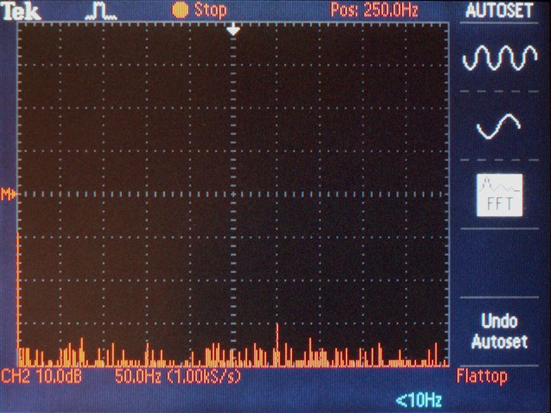
Figure 3. Background noise measurement, no signal present.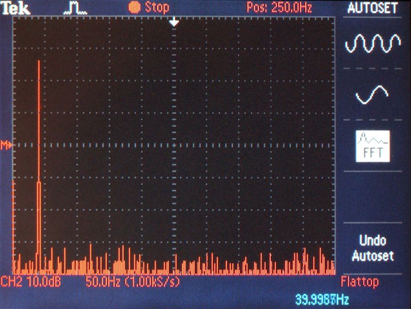
Figure 4. Configuration D - positive lead to LF positive post and negative lead to HF negative post, the negative jumper oriented from HF to LF, and the positive jumper oriented from LF to HF (best sounding).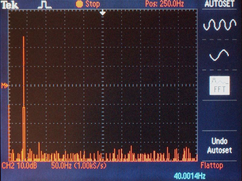
Figure. 5 Configuration A (corresponds to trial 8) - positive lead to LF positive post and negative lead to HF negative post, the positive and negative jumpers oriented from LF to HF (second best sounding).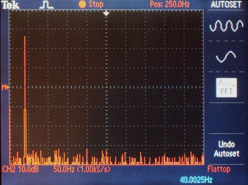
Figure. Configuration C (corresponds to trials 5 and 6) - positive lead to HF positive post and negative lead to LF negative post, the positive and negative jumpers oriented from LF to HF.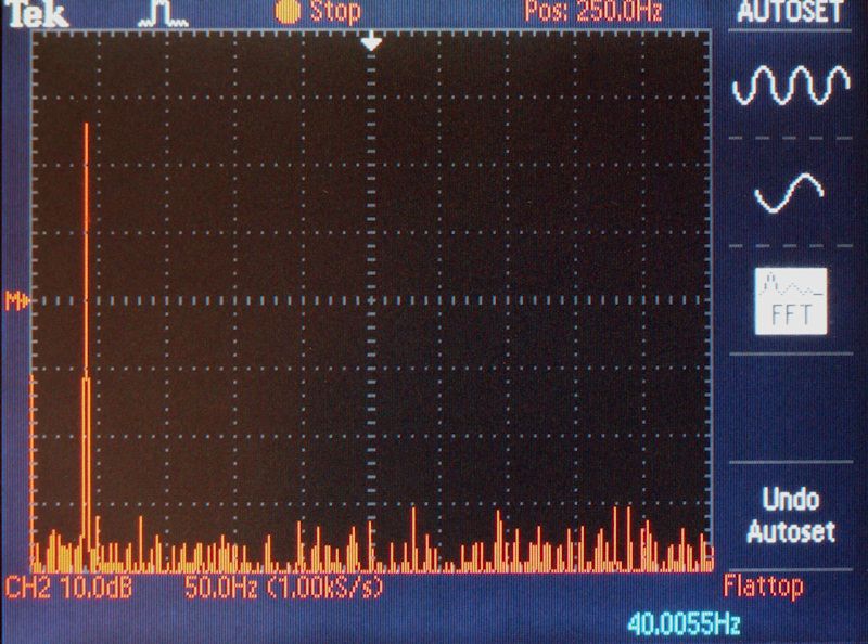
Figure. Configuration B (corresponds to trial 1) - positive lead to LF positive post and negative lead to LF negative post, the positive and negative jumpers oriented from LF to HF.Proud and loyal citizen of the Digital Domain and Solid State Country! -
DK, good job, as usual. Any chance to simultaneously capture the signal at the amp output, and speaker input to see if anything obvious stands out in comparison.
Also, would a setting of 62 give a higher SPL if using music versus a tone. I just measured my XP-20 at 52, and with Faith No More playing Epic, I measured in the 80/90s, using a RS digital SPL meter. I suspect the difference is the calibration scale used by Pass. The XP-20 goes from 0-83.Lumin X1 file player, Westminster Labs interconnect cable
Sony XA-5400ES SACD; Pass XP-22 pre; X600.5 amps
Magico S5 MKII Mcast Rose speakers; SPOD spikes
Shunyata Triton v3/Typhon QR on source, Denali 2000 (2) on amps
Shunyata Sigma XLR analog ICs, Sigma speaker cables
Shunyata Sigma HC (2), Sigma Analog, Sigma Digital, Z Anaconda (3) power cables
Mapleshade Samson V.3 four shelf solid maple rack, Micropoint brass footers
Three 20 amp circuits. -
Any chance to simultaneously capture the signal at the amp output, and speaker input to see if anything obvious stands out in comparison.
Sure, I could do that. My oscilloscope has two measurement channels. I could measure the amp output on one channel and the speaker input on another channel and display them simultaneously.Also, would a setting of 62 give a higher SPL if using music versus a tone.
Yes, if the music was recorded louder than the test tone. Using a complex signal like music would make it more difficult to tell what is noise and what is the signal of interest.The XP-20 goes from 0-83.
The XP-30 goes from 0-99 in 1 dB steps.
Proud and loyal citizen of the Digital Domain and Solid State Country! -
Nice well done experiment DK. I've discovered sonic benefits as well on my uncle's setup with his RTi's. He's happy. I 'll be giving this method a try on my new B&W 684 S2s and HTM 62 S2..Bday gift from the in-laws...BIG surprise for me!...no complaints here
 My Setup: Denon AVR X3600h, Polk Signature S50 Fronts w/ S30 Center and S15 Rears, LG UBK90 4K Player, TCL 6-Series 65”4k TV
 -
Measurements Continued
Measurements of room response were taken with Dayton Audio's OmniMic system. The calibrated microphone was placed at ear level on a tripod on the listening seat.
It will be easier to see differences in the plots if they are saved to your computer and viewed sequentially.
Figure 8. Room response with configuration D.
Figure 9. Room response with configuration A.
Figure 10. Room response with configuration B.
In figures 8 through 10, starting at 5kHz, there is a small progressive lowering of response (1to 2 dB) as you go from configuration D to A to B.
The color coded lines in the harmonic distortion plots represent the following:
Black - frequency response.
Dark blue - sum of 2nd-5th harmonics.
Red - 2nd harmonic.
Purple - 3rd harmonic.
Green - 4th harmonic.
Light blue - 5th harmonic.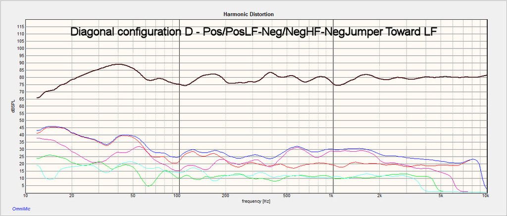
Figure 11. Harmonic distortion measurements with configuration D.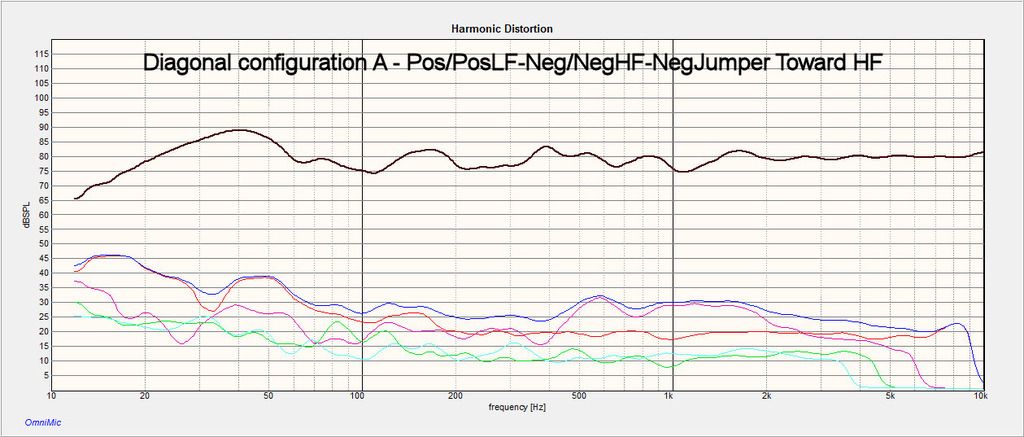
Figure 12. Harmonic distortion measurements with configuration A.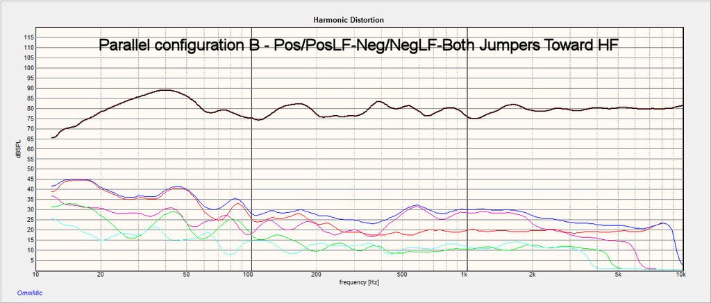
Figure 13. Harmonic distortion measurements with configuration B.
Harmonic distortion is essentially the same among the three configurations from 100 Hz upward. Between 20 Hz and 100 Hz, harmonic distortion levels increase as you go from configuration D to A to B.
Bass decay plots show how long it takes the sound to decay at each frequency. The ideal situation is flat response which means that some bass notes do not last much longer than others. Significant differences in decay times and very long decay times can cause a decrease in bass definition.
Figure 14. Bass decay times with configuration D.
Figure 15. Bass decay times with configuration A.
Figure 16. Bass decay times with configuration B.
For most of the frequency range from 20 Hz to 500 Hz, there were minor differences among the three configurations and they all showed good bass decay characteristics. There was a very small progressive increase in bass delay time at 23 Hz. Since there is very little music at or around this frequency, this will not be audible with most recordings.Post edited by DarqueKnight onProud and loyal citizen of the Digital Domain and Solid State Country! -
A Few Words About Termination Quality
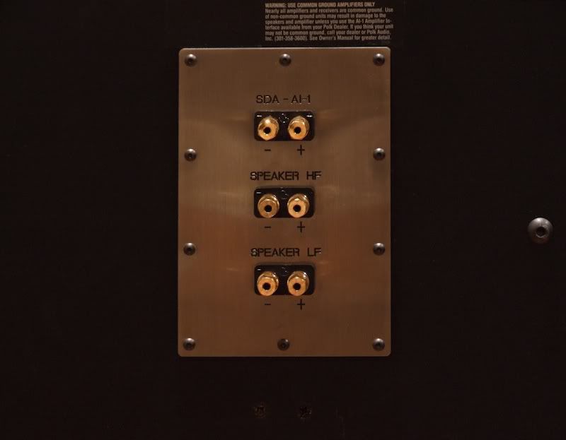
Figure 17. Custom aluminum binding post plate with Cardas CCGR-S binding posts.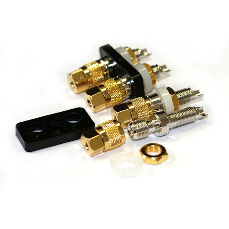
Figure 18. Cardas CCGR-S binding posts.
My speaker cable and jumper terminations are pure silver. Sulfur in the air causes silver to form a blackish tarnish composed of silver sulfide. Sulfer does not easily oxidize and form silver oxide. Silver sulfide is classified as a semiconductor and silver oxide is an insulator.
Unlike metallic conductors, whose electrical resistivity properties are fairly constant with regard to current and voltage, the electrical resistivity of semiconductors varies significantly with current and voltage level. Resistivities for silver, silver sulfide, silver oxide, copper and gold are as follows:
Silver: 0.00000001587 ohms-meter.
Silver sulfide: 0.1 to 1 ohm-meter.
Silver oxide: 1,000,000,000 ohms-meter.
Copper: 0.00000001678 ohms-meter.
Gold: 0.00000002214 ohms-meter.
The thick, sturdy, all metal Cardas CCGR-S posts form a very tight connection with the silver spades of my AudioQuest Everest speaker cables and with the silver banana plugs of my AudioQuest Perfect Surface Silver bi-wire jumpers. Figures 19 and 20 show that the portions of the spades and jumpers not under contact pressure from the Cardas posts are heavily tarnished while the portions under contact pressure are still bright and shiny.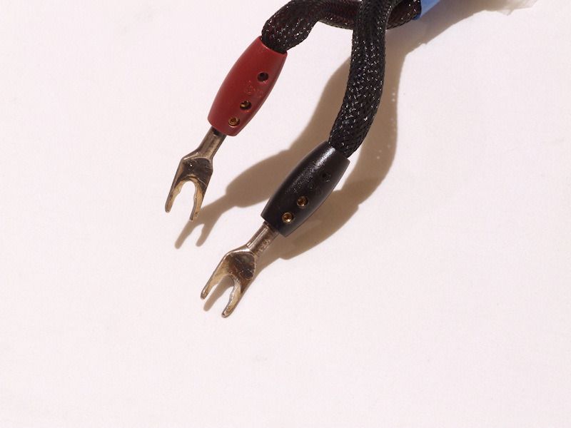
Figure 19. AudioQuest Everest speaker cable spades with silver sulfide tarnish.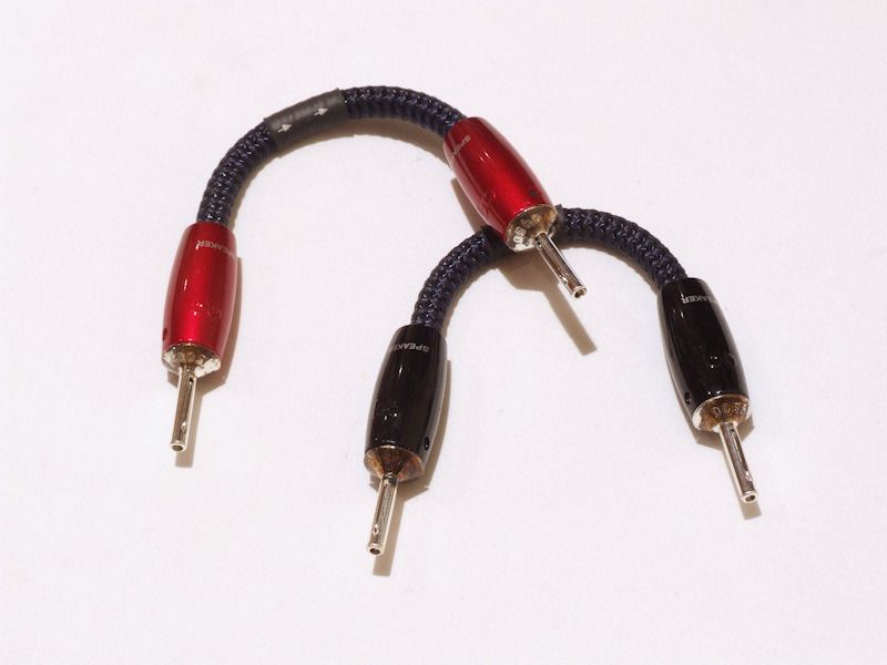
Figure 20. AudioQuest Perfect Surface Silver bi-wire jumpers with tarnished collars.
I measured the resistance of one 8.5 inch PSS jumper from one tarnished collar to the other using an Agilent 34401A digital multimeter. The meter was nulled out to subtract the resistance of the test leads. Continuity tests confirmed that the tarnished contacts were electrically conductive.
Resistance of leads: 0.073 ohm.
Resistance between untarnished silver banana plugs: -0.003 ohm.
Resistance between banana collars tarnished with silver sulfide: 0.162 ohm.
Resistance between untarnished silver banana plug and tarnished collar at other end: 0.062 ohm.
References
1. M. H. Hebb, "Electrical Conductivity of Silver Sulfide," The Journal of Chemical Physics, January 1952, Volume 20, Issue 1, pp. 185-190.
2. Zhang, J.G.; Lin, X.Y.; Sugimura, K., "Characteristics and electric contact behavior of tarnished film covered on silver plated surface formed by indoor air exposure," Proceedings of the Forty-Second IEEE Holm Conference on Electrical Contacts, 1996. Joint with the 18th International Conference on Electrical Contacts , pp. 429-437, September 16-20, 1996.
3. Russ, G., "Electrical Characteristics of Contacts Contaminated with Silver Sulfide Film," Parts, IEEE Transactions on Materials and Packaging, vol.6, no.4, pp.129-137, December 1970.
4. Simko, S.J.; Lee, A.; Gaarenstroom, S.W.; Dow, A.A.; Wong, Curtis A., "Film formation on silver-based switching contacts,", Proceedings of the Thirty Fifth Meeting of the IEEE Holm Conference on Electrical Contacts, 1989, pp.167-176, September 18-20, 1989.
Post edited by [Deleted User] onProud and loyal citizen of the Digital Domain and Solid State Country! -
Fascinating DK. I love the free tweaks that produce an audible improvement in SQ. I've been thinking about making some DIY silver ribbon SC's, but the amount of silver required is so danged expensive for a biwire set. May have to put together a single wire set and try the diagonal wiring."Science is suppose to explain observations not dismiss them as impossible" - Norm on AA; 2.3TL's w/sonicaps/mills/jantzen inductors, Gimpod's boards, Lg Solen SDA inductors, RD-0198's, MW's dynamatted, Armaflex speaker gaskets, H-nuts, brass spikes, Cardas CCGR BP's, upgraded IC Cable, Black Hole Damping Sheet strips, interior of cabinets sealed with Loctite Power Grab, AI-1 interface with 1000VA A-L transformer
-
Hi - may I ask how come your diagrams don't show up in your post ...... (I've logged into my photobucket acct, but to no avail)... Pls advise. Thx , yr post is of paramount importance to me !
-
Because photobucket demanded ransom money for people to continue using their site, but you should know that already.Political Correctness'.........defined
"A doctrine fostered by a delusional, illogical minority and rabidly promoted by an unscrupulous mainstream media, which holds forth the proposition that it is entirely possible to pick up a t-u-r-d by the clean end."
President of Club Polk -
Interesting that this came back up, and I'll have to give this a proper read. I saw something curiously similar in an AudioQuest document I was reading yesterday, where they'd shown a speaker side connection like this with the positive lead connected to the upper, jumpered to the lower, and the reverse for the negative lead. I thought it was some kind of error, or something that would reveal itself more clearly with further reading. Now I know why.I disabled signatures.
-
One thing to take into consideration is the tweeters are wired 180 out of phase on 1.2TL's internally. The positive side of the tweeters is wired to the negative binding post. 2.3TL's tweeters are wired the same way."Make a man a fire and he'll be warm for a day. Light
a man on fire and he'll be warm for the rest of his life." -
One thing to take into consideration is the tweeters are wired 180 out of phase on 1.2TL's internally. The positive side of the tweeters is wired to the negative binding post. 2.3TL's tweeters are wired the same way.
The tweeters of those SDAs have to be connected in reverse to account for a 180 degree phase shift of high frequencies caused by the crossover.
Diagonal wiring maintains proper phase connection at the binding posts: positive to positive and negative to negative. The differences are in moving the negative speaker cable connection up to the high frequency terminal and jumpering down to the low frequency terminal.
Proud and loyal citizen of the Digital Domain and Solid State Country! -
DarqueKnight wrote: »The tweeters of those SDAs have to be connected in reverse to account for a 180 degree phase shift of high frequencies caused by the crossover.
Interesting thread, glad it was resurrected.
When I changed out my terminal mounting plate and binding posts on my 2.3TL, I also used different leads to the crossover as well as a new Molex. I need to go back and look but does the crossover change the phase through the circuit board, or does the tweeter + input on the board need to be wired to the HF- on the binding post?
Or does this take place at the tweeter?
Your quote seems clear cut, just want to be sure. -
The crossover inverts the phase through the circuit board. Do not change any connections on the board since the +/- tweeter connections are already reversed to correct the phase shift (i.e., the tweeter's positive connections are already tied to the negative binding post, as shown in the crossover schematic.)
https://us.v-cdn.net/5021930/uploads/attachments/1/8/5/1/1/26696.pdfProud and loyal citizen of the Digital Domain and Solid State Country! -
Thanks.
I did see that in the schematic that the boards input positive appears to be terminated at the tweeters negative terminal, however my knowledge in schematics is limited.
Reading back a few posts I thought it almost sounded like the binding post positive went to the board input negative, gave me a moment of pause...


