Resistor Replacement For The SDA SRS 1.2TL Polyswitch

DarqueKnight
Posts: 6,765
Introduction
The effect on sound quality of substituting a resistor value for the tweeter protection polyswitch was evaluated in the SDA SRS 1.2TL. The crossover schematic specifies a Raychem RXE135 polyswitch, which has an initial resistance range of 0.12-0.19 ohm and a post-tripped maximum resistance of 0.30 ohm. The equivalent DC resistance of the SDA SRS 1.2TL tweeter circuit (including the four tweeters, two 0.4 mH inductors and 0.7 mH inductor) is 1.97 ohms.
Polk's engineering department has advised that the removal of the polyswitch in SDA series loudspeakers, and replacing it with a wire jumper, can result in improved sound quality. However, the owner is cautioned to use high quality amplification and to not be careless with the volume control. Technical specifications for the polyswitches used in SDA loudspeakers can be found as attachments to this thread:
Evaluation Procedure
Three Mills MRA-12 resistor values were purchased: 0.1 ohm, 0.15 ohm and 0.5 ohm. The 0.15 ohm resistor was only one within the initial resistance range of the polyswitch and it was the only value used in this report. I had planned to do listening and measurement comparisons of all the resistors and the polyswitch, but I decided to wait and do that in the future, when I am more dedicated to audio than I am now. I have done extensive listening tests between the polyswitched and un-polyswitched SDA models I own or have owned: CRS+, SDA SRS, SDA 1B, SDA 1C, and SDA SRS 1.2TL. In each case, the veil removed by replacing the polyswitch with a solid core copper jumper wire was substantial.
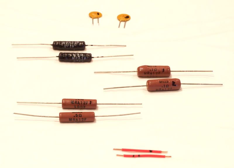
Figure 1. Top to bottom: RXE135 polyswitches, 0.15 ohm resistors, 0.1 ohm resistors, 0.5 ohm resistors,
1.5" 18 AWG jumper wires.
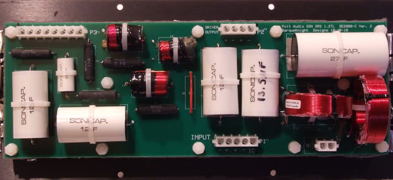
Figure 2. SDA SRS 1.2TL crossover with wire jumper.
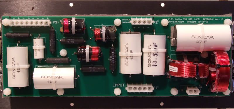
Figure 3. SDA SRS 1.2TL crossover with Mills MRA-12 0.15 ohm resistor.
The jumper in the right speaker was replaced first and compared to the left in stereo and mono modes with CD's, SACD's and vinyl records. Listening was done at the normal seated position and taking turns standing two feet in front of each speaker while listening in mono mode. Notes were made of sound quality, image placement and tactile sensations. Next, the jumper was replaced in the left speaker and the listening tests were repeated.
Summary of Listening Evaluation Results
1. There was an overall slight veiling.
2. The center image was enhanced in apparent sound level at the expense of the side images, which decreased in apparent sound level, clarity and detail. This effect varied by recording.
3. The key noise on some saxophone recordings was diminished. There was a slight tizziness added to some saxophone solos on digital and analog recordings.
4. The vocals on all vinyl records acquired an annoying slight sibilance. Tizziness was also heard on metallic percussion instruments on LP. The opposite was heard on digital recordings: vocals and metallic percussion instruments took on a "mellower", more subdued sound.
5. I was most surprised at the diminished tactile sensation and diminished bass detail.
Measurements

Figure 4. Frequency response measurements with jumper and 0.15 ohm resistor.
The color coded lines in the harmonic distortion plots represent the following:
Black - frequency response.
Dark blue - sum of 2nd-5th harmonics.
Red - 2nd harmonic.
Purple - 3rd harmonic.
Green - 4th harmonic.
Light blue - 5th harmonic.
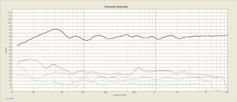
Figure 5. Harmonic distortion with jumper.
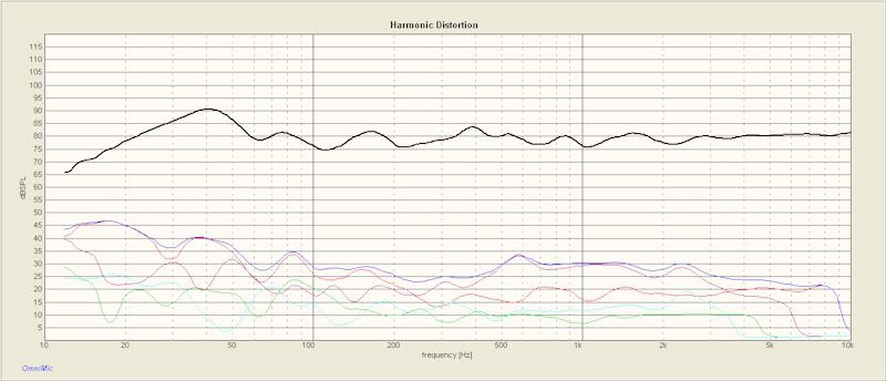
Figure 6. Harmonic distortion with 0.15 ohm resistor.
Replacing the jumper with the 0.15 ohm resistor caused a decrease in the "good" (even order) harmonics and a significant increase in the "bad" (odd order) harmonics in the bass region below 200 Hz. From 1kHz and up, the distortion products are very similar between the jumper and 0.15 ohm resistor, with the exceptions of the resistor causing a small increase in the 5th harmonic at 2500 Hz and 2nd harmonic at 7500 Hz.
The bass decay plots show how long it takes the sound to decay at each frequency. As shown on the legend to the right of the decay graph, the white area extends upward to indicate when the level drops no more than 5 decibels (dB). The light blue indicates when the level has dropped between 5dB and 10dB, etc. The ideal situation is not to have some bass notes lasting much longer than others. Significant differences in decay times can cause a decrease in bass definition.
On average, the bass decay was similar in both cases.

Figure 7. Bass decay with jumper.

Figure 8. Bass decay with 0.15 ohm resistor.
Discussion of Resistor Substitution in SDA's
Since polyswitches have some electrical resistance, some SDA owners believe this resistance was accounted for in the speaker design and must be replaced if the polyswitch is removed. Some owners have reported improved sound quality by replacing a polyswitch with a resistor, rather than a wire jumper. Depending on individual listening preferences, replacing a polyswitch with a resistor may or may not result in more pleasing sound. My advice is to try both ways to be sure. For 3rd through 5th generation SDA's (1986 and after) the schematics and advisement from Polk's engineering department appear to indicate that a resistor substitution is not required (the earliest SRS 3.1TL's are an exception).
The 4th generation SDA 1C has used three different polyswitches with no tweeter circuit compensation for the variance in polyswitch resistance:
1. RDE070A, initial resistance range 0.25-0.40 ohm, post trip maximum resistance of 0.6 ohm.
2. RXE135, initial resistance range 0.12-0.19 ohm, post trip maximum resistance of 0.3 ohm.
3. RDE050A, initial resistance range 0.50-0.77 ohm, post trip maximum resistance of 1.17 ohm.
The equivalent DC resistance of the SDA 1C tweeter circuit (including the DC resistance of the two tweeters and two 0.4 mH inductors) is 2.3 ohms.
Note that the SDA 1C schematic indicates a change from the RDE070A to the RXE135. I have found no documentation on the use of the RDE050A. However, a pair of SDA 1C's that I owned used RDE050A's.
In the 4th generation SDA SRS 1.2, the RDE070A was replaced with the RDE090:
1. RDE070A, initial resistance range 0.25-0.40 ohm, post trip maximum resistance of 0.6 ohm.
2. RDE090, initial resistance range 0.07-0.12 ohm, post trip maximum resistance of 0.22 ohm.
In the 4th generation SDA 2B and SDA CRS+ (both models used the same crossover circuit), the RDE050A was replaced with the RDE090:
1. RDE050A, initial resistance range 0.50-0.77 ohm, post trip maximum resistance of 1.17 ohm.
2. RDE090, initial resistance range 0.07-0.12 ohm, post trip maximum resistance of 0.22 ohm.
For my 3rd generation SDA 1B's, I was advised by Polk's engineering department to replace the RDE090 with a wire jumper:
1. RDE090, initial resistance range 0.07-0.12 ohm, post trip maximum resistance of 0.22 ohm.
2. Wire jumper, resistance on the order of 0.009 ohm or less.
The 5th generation SDA SRS 3.1TL is a special case. It is the only SDA model that was revised to have its polyswitch removed. When Matthew Polk was asked about the reason for this, he explained:
"I don't know for sure. We were having some trouble at the time with inconsistency on the polyswitches and may have decided that it was simply not necessary due to the lower power handing of the 3.1 Ultimately we determined that the trip current of the polyswitch prior to being tripped the first time was significantly higher than its rating. As I recall we then began a program of pre-conditioning polyswitches by tripping them prior to installation."
When the 3.1TL's RXE135 polyswitch was removed, the 1 ohm tweeter resistor was replaced with a 1.3 ohm resistor. The post-tripped resistance of the RXE135 is 0.30 ohm, therefore in the case of the single tweeter, single resistor 3.1TL, removing the polyswitch did, and does, require a change in the tweeter resistor value.
In the 2nd generation SDA 2 and SDA CRS, the tweeter fuses were replaced with RDE050A polyswitches. The tweeter resistors were reduced in value by 0.5 ohm to account for the nominal 0.5 ohm resistance of the RDE050A.
Conclusion
Compared to a copper wire jumper, a resistor comparable to the resistance value of the RXE135 polyswitch resulted lower sound quality and higher levels of measurable and audible distortion. Going on prior listening notes and memory, the sound quality of the 0.15 ohm resistor falls between the polyswitch and the jumper.
The effect on sound quality of substituting a resistor value for the tweeter protection polyswitch was evaluated in the SDA SRS 1.2TL. The crossover schematic specifies a Raychem RXE135 polyswitch, which has an initial resistance range of 0.12-0.19 ohm and a post-tripped maximum resistance of 0.30 ohm. The equivalent DC resistance of the SDA SRS 1.2TL tweeter circuit (including the four tweeters, two 0.4 mH inductors and 0.7 mH inductor) is 1.97 ohms.
Polk's engineering department has advised that the removal of the polyswitch in SDA series loudspeakers, and replacing it with a wire jumper, can result in improved sound quality. However, the owner is cautioned to use high quality amplification and to not be careless with the volume control. Technical specifications for the polyswitches used in SDA loudspeakers can be found as attachments to this thread:
Evaluation Procedure
Three Mills MRA-12 resistor values were purchased: 0.1 ohm, 0.15 ohm and 0.5 ohm. The 0.15 ohm resistor was only one within the initial resistance range of the polyswitch and it was the only value used in this report. I had planned to do listening and measurement comparisons of all the resistors and the polyswitch, but I decided to wait and do that in the future, when I am more dedicated to audio than I am now. I have done extensive listening tests between the polyswitched and un-polyswitched SDA models I own or have owned: CRS+, SDA SRS, SDA 1B, SDA 1C, and SDA SRS 1.2TL. In each case, the veil removed by replacing the polyswitch with a solid core copper jumper wire was substantial.

Figure 1. Top to bottom: RXE135 polyswitches, 0.15 ohm resistors, 0.1 ohm resistors, 0.5 ohm resistors,
1.5" 18 AWG jumper wires.
Table 1.
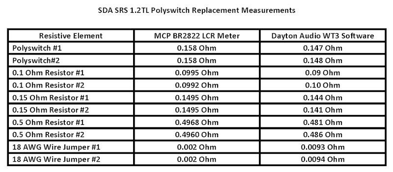


Figure 2. SDA SRS 1.2TL crossover with wire jumper.

Figure 3. SDA SRS 1.2TL crossover with Mills MRA-12 0.15 ohm resistor.
The jumper in the right speaker was replaced first and compared to the left in stereo and mono modes with CD's, SACD's and vinyl records. Listening was done at the normal seated position and taking turns standing two feet in front of each speaker while listening in mono mode. Notes were made of sound quality, image placement and tactile sensations. Next, the jumper was replaced in the left speaker and the listening tests were repeated.
Summary of Listening Evaluation Results
1. There was an overall slight veiling.
2. The center image was enhanced in apparent sound level at the expense of the side images, which decreased in apparent sound level, clarity and detail. This effect varied by recording.
3. The key noise on some saxophone recordings was diminished. There was a slight tizziness added to some saxophone solos on digital and analog recordings.
4. The vocals on all vinyl records acquired an annoying slight sibilance. Tizziness was also heard on metallic percussion instruments on LP. The opposite was heard on digital recordings: vocals and metallic percussion instruments took on a "mellower", more subdued sound.
5. I was most surprised at the diminished tactile sensation and diminished bass detail.
Measurements

Figure 4. Frequency response measurements with jumper and 0.15 ohm resistor.
The color coded lines in the harmonic distortion plots represent the following:
Black - frequency response.
Dark blue - sum of 2nd-5th harmonics.
Red - 2nd harmonic.
Purple - 3rd harmonic.
Green - 4th harmonic.
Light blue - 5th harmonic.

Figure 5. Harmonic distortion with jumper.

Figure 6. Harmonic distortion with 0.15 ohm resistor.
Replacing the jumper with the 0.15 ohm resistor caused a decrease in the "good" (even order) harmonics and a significant increase in the "bad" (odd order) harmonics in the bass region below 200 Hz. From 1kHz and up, the distortion products are very similar between the jumper and 0.15 ohm resistor, with the exceptions of the resistor causing a small increase in the 5th harmonic at 2500 Hz and 2nd harmonic at 7500 Hz.
The bass decay plots show how long it takes the sound to decay at each frequency. As shown on the legend to the right of the decay graph, the white area extends upward to indicate when the level drops no more than 5 decibels (dB). The light blue indicates when the level has dropped between 5dB and 10dB, etc. The ideal situation is not to have some bass notes lasting much longer than others. Significant differences in decay times can cause a decrease in bass definition.
On average, the bass decay was similar in both cases.

Figure 7. Bass decay with jumper.

Figure 8. Bass decay with 0.15 ohm resistor.
Discussion of Resistor Substitution in SDA's
Since polyswitches have some electrical resistance, some SDA owners believe this resistance was accounted for in the speaker design and must be replaced if the polyswitch is removed. Some owners have reported improved sound quality by replacing a polyswitch with a resistor, rather than a wire jumper. Depending on individual listening preferences, replacing a polyswitch with a resistor may or may not result in more pleasing sound. My advice is to try both ways to be sure. For 3rd through 5th generation SDA's (1986 and after) the schematics and advisement from Polk's engineering department appear to indicate that a resistor substitution is not required (the earliest SRS 3.1TL's are an exception).
The 4th generation SDA 1C has used three different polyswitches with no tweeter circuit compensation for the variance in polyswitch resistance:
1. RDE070A, initial resistance range 0.25-0.40 ohm, post trip maximum resistance of 0.6 ohm.
2. RXE135, initial resistance range 0.12-0.19 ohm, post trip maximum resistance of 0.3 ohm.
3. RDE050A, initial resistance range 0.50-0.77 ohm, post trip maximum resistance of 1.17 ohm.
The equivalent DC resistance of the SDA 1C tweeter circuit (including the DC resistance of the two tweeters and two 0.4 mH inductors) is 2.3 ohms.
Note that the SDA 1C schematic indicates a change from the RDE070A to the RXE135. I have found no documentation on the use of the RDE050A. However, a pair of SDA 1C's that I owned used RDE050A's.
In the 4th generation SDA SRS 1.2, the RDE070A was replaced with the RDE090:
1. RDE070A, initial resistance range 0.25-0.40 ohm, post trip maximum resistance of 0.6 ohm.
2. RDE090, initial resistance range 0.07-0.12 ohm, post trip maximum resistance of 0.22 ohm.
In the 4th generation SDA 2B and SDA CRS+ (both models used the same crossover circuit), the RDE050A was replaced with the RDE090:
1. RDE050A, initial resistance range 0.50-0.77 ohm, post trip maximum resistance of 1.17 ohm.
2. RDE090, initial resistance range 0.07-0.12 ohm, post trip maximum resistance of 0.22 ohm.
For my 3rd generation SDA 1B's, I was advised by Polk's engineering department to replace the RDE090 with a wire jumper:
1. RDE090, initial resistance range 0.07-0.12 ohm, post trip maximum resistance of 0.22 ohm.
2. Wire jumper, resistance on the order of 0.009 ohm or less.
The 5th generation SDA SRS 3.1TL is a special case. It is the only SDA model that was revised to have its polyswitch removed. When Matthew Polk was asked about the reason for this, he explained:
"I don't know for sure. We were having some trouble at the time with inconsistency on the polyswitches and may have decided that it was simply not necessary due to the lower power handing of the 3.1 Ultimately we determined that the trip current of the polyswitch prior to being tripped the first time was significantly higher than its rating. As I recall we then began a program of pre-conditioning polyswitches by tripping them prior to installation."
When the 3.1TL's RXE135 polyswitch was removed, the 1 ohm tweeter resistor was replaced with a 1.3 ohm resistor. The post-tripped resistance of the RXE135 is 0.30 ohm, therefore in the case of the single tweeter, single resistor 3.1TL, removing the polyswitch did, and does, require a change in the tweeter resistor value.
In the 2nd generation SDA 2 and SDA CRS, the tweeter fuses were replaced with RDE050A polyswitches. The tweeter resistors were reduced in value by 0.5 ohm to account for the nominal 0.5 ohm resistance of the RDE050A.
Conclusion
Compared to a copper wire jumper, a resistor comparable to the resistance value of the RXE135 polyswitch resulted lower sound quality and higher levels of measurable and audible distortion. Going on prior listening notes and memory, the sound quality of the 0.15 ohm resistor falls between the polyswitch and the jumper.
Proud and loyal citizen of the Digital Domain and Solid State Country!
Post edited by DarqueKnight on
Comments
-
DarqueKnight wrote: »Compared to a copper wire jumper, a resistor comparable to the resistance value of the RXE135 polyswitch resulted lower sound quality and higher levels of measurable and audible distortion.
Just as I suspected. Polyswitches or resistors in that position are nasty (if I may steal your phrase). Nice review.SDA SRS 2.3TL's
Silk Audio MS-90-BT integrated tube amp
Yaqin MS-20L integrated tube amp
SDA 2B TL's -
[PHP][/PHP]michaeljhsda2 wrote: »resistors in that position are nasty
So because DK says so you say they are nasty? Have you tried it?
Nice write up Ray.. -
[PHP][/PHP]
So because DK says so you say they are nasty? Have you tried it?
Nice write up Ray..
No. Yes.SDA SRS 2.3TL's
Silk Audio MS-90-BT integrated tube amp
Yaqin MS-20L integrated tube amp
SDA 2B TL's -
michaeljhsda2 wrote: »No. Yes.
:cool: -
Since I will be putting in my inductors next weekend I will pull the resistors back out and just put in a jumper wire again and report back..
-
I've tried it all three ways in my old SDA-1C's:
Polys = Horrible (think mine were "slam wore out" as we say in the south)
Jumper = Great if you like it hot and I do at times
0.5 ohm Mills resistor = Perfect for me
Thanks DK for the write up and time. Very well done!!! -
As usual Ray, nice write up.In each case, the veil removed by replacing the polyswitch with a solid core copper jumper wire was substantial.
I agree the difference is substantial, but to me it results in too much high frequency energy, which could be taken for the lifting of a veil. Some may like that, others not so much.
I realize that you performed your tests on different speakers than I and that makes my following comment a somewhat apples to oranges comparision. Anyway, as I have stated in the past my experiences with 2BTL's, 4.1TL's and 2.3TL's, using only my ears as the test equipment, have shown that the .5 ohm Mills improved the overall sound quality.My advice is to try both ways to be sure.
Excellent advice.Political Correctness'.........defined
"A doctrine fostered by a delusional, illogical minority and rabidly promoted by an unscrupulous mainstream media, which holds forth the proposition that it is entirely possible to pick up a t-u-r-d by the clean end."
President of Club Polk -
I've tried jumper, .5 mills, and now have .47 Mundorfs on my 2BTL's. I've had the .47 Mundorfs in for a couple of months now and they bring down the highs a tad to much for my liking. I will pull them out tonight and jump the position.
The .5 mills in my system wasn't bad at all, I just preferred using a jumper. -
I realize that you performed your tests on different speakers than I and that makes my following comment a somewhat apples to oranges comparision.
I would consider your results valid even if you had the same speakers, with all the same tweaks, as long as good testing procedure was used. I think it's good to get as much feedback as possible from a variety of listening environments.Anyway, as I have stated in the past my experiences with 2BTL's, 4.1TL's and 2.3TL's, using only my ears as the test equipment, have shown that the .5 ohm Mills improved the overall sound quality.
That's the best test equipment available...and really the only test equipment that matters. Proud and loyal citizen of the Digital Domain and Solid State Country!
 -
DarqueKnight wrote: »I think it's good to get as much feedback as possible from a variety of listening environments.
That is the one thing that hampers some here, including me. I have only one system on which to listen so really no reference. My worst fear is that one day I will get to hear some other high quality gear and realize mine sounds terrible. It really helps to have these kind of discussions.
I used the .27 Mills resistor in my 2BTLs and I like it there. Still tweaking my power amp though so that may change. Great write up and thanks for posting it.SDA2BTL
Marantz CD5004
Adcom GFA-545
Bottlehead Quickie Tube Preamp -
...as I have stated in the past my experiences with 2BTL's, 4.1TL's and 2.3TL's...audiocr381ve wrote: »I've tried jumper, .5 mills, and now have .47 Mundorfs on my 2BTL's. I've had the .47 Mundorfs in for a couple of months now and they bring down the highs a tad to much for my liking. I will pull them out tonight and jump the position.
The .5 mills in my system wasn't bad at all, I just preferred using a jumper.
I have the TL'ed version of the CRS+ (also referred to as the 4.1TL) which uses the same crossover as the SDA 2B. I'll pop in the 0.5 ohm Mills and see how I like it.
I'm curious about this because using a 0.5 ohm resistor goes in the opposite direction that Polk went when they replaced the original SDA 2B/SDA CRS+ RDE050A polyswitch (0.5-0.77 ohm resistance range) with a RDE090 (0.07-0.12 ohm resistance range).Proud and loyal citizen of the Digital Domain and Solid State Country! -
DarqueKnight wrote: »I'm curious about this because using a 0.5 ohm resistor goes in the opposite direction that Polk went when they replaced the original SDA 2B/SDA CRS+ RDE050A polyswitch (0.5-0.77 ohm resistance range) with a RDE090 (0.07-0.12 ohm resistance range).
I'm certain that the associated gear, the room and personal preferences play a role in the varied opinions on this subject matter. For example, some folks still prefer the SL2000 with it's spike to the RD0194-1.Political Correctness'.........defined
"A doctrine fostered by a delusional, illogical minority and rabidly promoted by an unscrupulous mainstream media, which holds forth the proposition that it is entirely possible to pick up a t-u-r-d by the clean end."
President of Club Polk -
I'm certain that the associated gear, the room and personal preferences play a role in the varied opinions on this subject matter. For example, some folks still prefer the SL2000 with it's spike to the RD0194-1.
The way source material is recorded plays a big role too. A lot of pop and rock is recorded "hot". If someone listens to a lot of those type of recordings, I can see where toning the highs down a bit would result in more balanced sound.For example, some folks still prefer the SL2000 with it's spike to the RD0194-1.
Yeah, the silk domes, particularly the RD0198, sound too "dull" and "rolled off" for some people.:sad:Proud and loyal citizen of the Digital Domain and Solid State Country! -
DarqueKnight wrote: »I have the TL'ed version of the CRS+ (also referred to as the 4.1TL) which uses the same crossover as the SDA 2B. I'll pop in the 0.5 ohm Mills and see how I like it.
I'm curious about this because using a 0.5 ohm resistor goes in the opposite direction that Polk went when they replaced the original SDA 2B/SDA CRS+ RDE050A polyswitch (0.5-0.77 ohm resistance range) with a RDE090 (0.07-0.12 ohm resistance range).
This will be interesting Ray. I prefer the 0.5 ohm in the 2BTL's (I have the single crossover 1987 blade/blade 2B's), but not sure I like it as much in the 2.3TL's. It does have a veiled effect to the high end and detail. I am going by memory from hearing my 2BTL's though. It will be interesting to see what the Duelunds do to the high end in the 2.3TL's. Also, it could be I like the Duelund effect of the 0.5 ohm resistor in the polyswitch spot opposed to the Mills 0.5 ohm resistor in the polyswitch spot (which is what's in there now. When I redo my crossovers in the 2.3TL's using Duelund resistors and Clarity Cap ESA caps, I will try using a jumper in the polyswitch spot first and then add the 0.5 ohm resistor to hear the differences.
Thanks for this timely review Ray. It was very nicely timed. Especially with so many people discussing adding resistors in their crossover makeovers.
Greg
Taken from a recent Audioholics reply regarding "Club Polk" and Polk speakers:
"I'm yet to hear a Polk speaker that merits more than a sentence and 60 seconds discussion."
My response is: If you need 60 seconds to respond in one sentence, you probably should't be evaluating Polk speakers.....
"Green leaves reveal the heart spoken Khatru"- Jon Anderson
"Have A Little Faith! And Everything You'll Face, Will Jump From Out Right On Into Place! Yeah! Take A Little Time! And Everything You'll Find, Will Move From Gloom Right On Into Shine!"- Arthur Lee -
I'm certain that the associated gear, the room and personal preferences play a role in the varied opinions on this subject matter. For example, some folks still prefer the SL2000 with it's spike to the RD0194-1.
Crazy! (IMO).:biggrin:
Greg
Taken from a recent Audioholics reply regarding "Club Polk" and Polk speakers:
"I'm yet to hear a Polk speaker that merits more than a sentence and 60 seconds discussion."
My response is: If you need 60 seconds to respond in one sentence, you probably should't be evaluating Polk speakers.....
"Green leaves reveal the heart spoken Khatru"- Jon Anderson
"Have A Little Faith! And Everything You'll Face, Will Jump From Out Right On Into Place! Yeah! Take A Little Time! And Everything You'll Find, Will Move From Gloom Right On Into Shine!"- Arthur Lee -
DarqueKnight wrote: »I have the TL'ed version of the CRS+ (also referred to as the 4.1TL) which uses the same crossover as the SDA 2B. I'll pop in the 0.5 ohm Mills and see how I like it.
I'm curious about this because using a 0.5 ohm resistor goes in the opposite direction that Polk went when they replaced the original SDA 2B/SDA CRS+ RDE050A polyswitch (0.5-0.77 ohm resistance range) with a RDE090 (0.07-0.12 ohm resistance range).
Pulled the Mundorf .47's out of the 2BTL's tonight. Holy moly. Sounds incredible. I tried to put on music that would give the highs a chance to sound bright like One Republic and Coldplay, but it sounds just right with out a resistor to replace the polyswitch. I did this same thing awhile back but with the .5 mills as well. I gave it a few months, took it out, and gave the jumper a few months.
My conclusion after all of my own tests in my system with my ears is that I like what I'm hearing with out a resistor to replace the polyswitch. Thanks for all the hard work you put into this DK! I agree with your findings. -
audiocr381ve wrote: »Pulled the Mundorf .47's out of the 2BTL's tonight. Holy moly. Sounds incredible. I tried to put on music that would give the highs a chance to sound bright like One Republic and Coldplay, but it sounds just right with out a resistor to replace the polyswitch. I did this same thing awhile back but with the .5 mills as well. I gave it a few months, took it out, and gave the jumper a few months.
My conclusion after all of my own tests in my system with my ears is that I like what I'm hearing with out a resistor to replace the polyswitch. Thanks for all the hard work you put into this DK! I agree with your findings.
You came to that conclusion even though one of your speakers isn't working properly. http://www.polkaudio.com/forums/showthread.php?128278-Dimensional-driver-issues-SDA-2BTL
Yes, I realize it's not the tweeter....still.Political Correctness'.........defined
"A doctrine fostered by a delusional, illogical minority and rabidly promoted by an unscrupulous mainstream media, which holds forth the proposition that it is entirely possible to pick up a t-u-r-d by the clean end."
President of Club Polk -
Having tried a Jumper, a .5 mills and as PreCd has with a .27 I believe the .27 is perfect. It pulls the highs back just enough and but not nearly as much as the .5 and sounds 100 times better than the Poly's.
-
I have a .22 mills in mine and it seems to be the right balance with my associated gear and room.I like speakers that are bigger than a small refrigerator but smaller than a big refrigerator:D
-
MillerLiteScott wrote: »I have a .22 mills in mine and it seems to be the right balance with my associated gear and room.
Exact same situation here
Burson HA-160D > Adcom GFA-5802 > Polk SDA-SRS 1.2tl w/ Mye Sound Spikes, Mills/Sonicap XO, Larry's Rings, Dynamat Extreme, Cardas CCGR Binding Posts and Jumpers, Custom 10ga interconnect, Custom Gaskets, RDO-198 -
I have an older set of Polk SDA2's they have blade/blade I/C wire, 3 midwoof's and the Passive radiator. Anyway, when I go to really crank them the tweeters drop out for a minute (presumably to cool down) I have read a bunch of posts about replacing them, but am not sure where they live. Is the Mills cap the best solution? Where can i find one locally? Anything else I should get while I'm there? Is the a picture showing what they look like? Thanks for your help!!
-
I have an older set of Polk SDA2's they have blade/blade I/C wire, 3 midwoof's and the Passive radiator. Anyway, when I go to really crank them the tweeters drop out for a minute (presumably to cool down) I have read a bunch of posts about replacing them, but am not sure where they live. Is the Mills cap the best solution? Where can i find one locally? Anything else I should get while I'm there? Is the a picture showing what they look like? Thanks for your help!!
The Mills cap lives at parts express
Where's locally?
Look for a better amp while you're there.Gustard X26 Pro DAC
Belles 21A Pre Upgraded with Mundorf Supremes
B&K M200 Sonata monoblocks refreshed and upgraded
Polk SDA 1C's modded / 1000Va Dreadnaught
Wireworld Silver Eclipse IC's and speaker cables
Harman Kardon T65C w/Grado Gold. (Don't laugh. It sounds great!)
There is about a 5% genetic difference between apes and men …but that difference is the difference between throwing your own poo when you are annoyed …and Einstein, Shakespeare and Miss January. by Dr. Sardonicus -
"the Mills" is a resistor, not a capacitor. They're not found locally, at least for most of us--one place to order them is at soniccraft.com, the MRA-12 or MRA-10 should be sufficient, in a value of roughly .5ohm
Here's a working link to the thread "Polyswitches are Nasty" (broken link above), it has pictures of the various polyswitches Polk used--the shapes and colors changed a few times over the years. If you posted a picture of your crossover, people could point out what to remove/replace with a resistor.
Not too many pictures of original SDA2's on the forum, at least in my memory, so you uploading a picture would help. I'd recommend that you start your own thread in either "Vintage" or "Troubleshooting" for the most views/assistance.
Good luck!
Edit: Hey! It looks like someone was working on the original SDA2's in that thread. Hope that discussion helps you.
Jay
SDA 2BTL * McCormack DNA 0.5 amp * Oppo BDP-93 * Modded Adcom GDA-600 DAC * Rythmik F8 (x2)
Micro Seiki DQ-50 * Hagerman Cornet 2 Phono * A hodgepodge of cabling * Belkin PF60
Preamp rotation: Krell KSL (SCompRacer recapped) * Manley Shrimp * PS Audio 5.0 -
I have an older set of Polk SDA2's they have blade/blade I/C wire, 3 midwoof's and the Passive radiator. Anyway, when I go to really crank them the tweeters drop out for a minute (presumably to cool down) I have read a bunch of posts about replacing them, but am not sure where they live. Is the Mills cap the best solution? Where can i find one locally? Anything else I should get while I'm there? Is the a picture showing what they look like? Thanks for your help!!
If you are turning the volume knob up to 11, 12 or past you have gone too far and your power source is starting to clip.Political Correctness'.........defined
"A doctrine fostered by a delusional, illogical minority and rabidly promoted by an unscrupulous mainstream media, which holds forth the proposition that it is entirely possible to pick up a t-u-r-d by the clean end."
President of Club Polk


