Custom Printed Circuit Board And SDA Inductor For The SDA 1.2TL - Preliminary Results
Options

DarqueKnight
Posts: 6,765
Introduction
Several years ago, after I had posted a thread on an SDA crossover modification, forum member Madmax mentioned the option of having custom printed circuit boards made for my SDA crossover modifications. This stayed in the back of my mind and was recently brought to the front by the recent custom printed circuit board work of forum member Gim54pod.
I have also appreciated the sharing of results by those who have replaced the inductors in their SDA's (Janne, Ben62670 and others). In addition to a custom crossover circuit board, I have replaced the large 16 mH SDA inductor in my SDA SRS 1.2TL's.
Board Layout
The custom board was designed (by me ) with ExpressPCB software (free from www.expresspcb.com). The high frequency components are on the board's left and the low frequency components on the right (figures 1, 2 and 5).
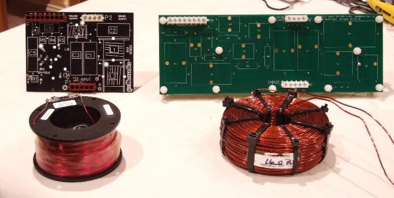
Figure 1. Stock 1.2TL crossover circuit board and 16 mH SDA inductor on left.
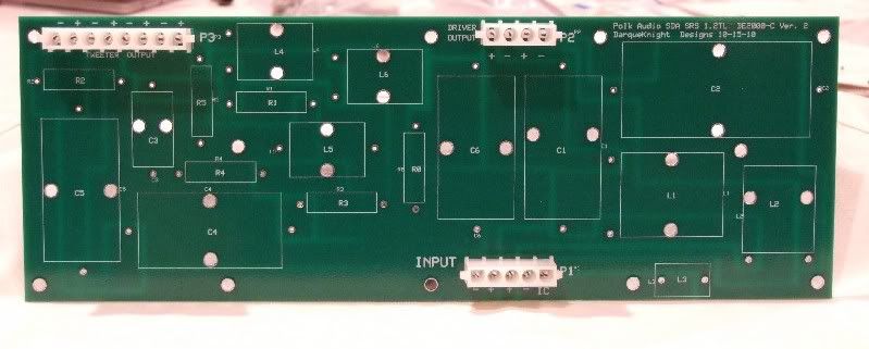
Figure 2. Custom 1.2TL crossover circuit board with AMP Mate-N-Lock wiring connectors installed.
The polarity markings for the tweeter wiring connector are wrong (upper left in figure 2). I did not remember that the 1.2TL uses the same board as the crossover board as the 1.2. I did not realize the error until after a discussion about the 1.2TL circuit board with Gim54pod. The polarity markings are correct for the 1.2 but not the 1.2TL.
I also could have added another inch to the right side of the board in order to provide more space for the standoff nut between L1, L2 and C2 (figures 1 and 5). The nut is accessible with needle nose pliers. However, after assembly, I found that I would have preferred more space around the nut. Aside from this and the tweeter polarity marking error, I am very pleased with the way the board turned out.
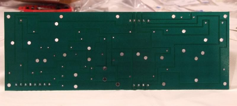
Figure 3. Bottom of custom circuit board showing circuit traces.
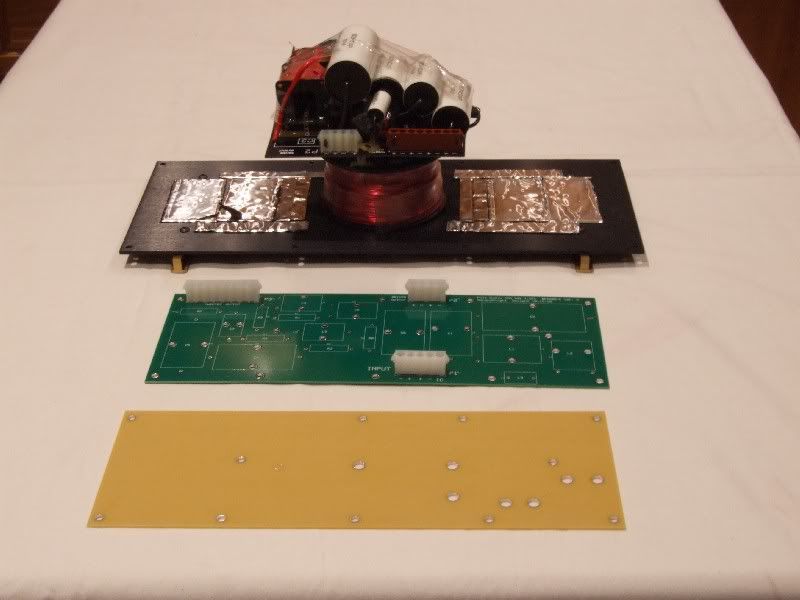
Figure 4. The stock modified crossover is at top, next is the custom crossover board, at the bottom is the support board for the
main board.
The stock board was already crammed to overflowing with "normal" sized parts. The stock modified crossover with larger, higher performance capacitors was a jumbled mess. The resistors even had to be mounted on the underside of the stock board. The new board provides an orderly platform and easily facilities the replacement of parts if required or desired.
The new board measures 12" wide by 4.2 inches high. The cabinet opening for the crossover is 14-3/16" wide by 4-3/4" high. The support board prevents flexing in the long main circuit board (see figure 7).
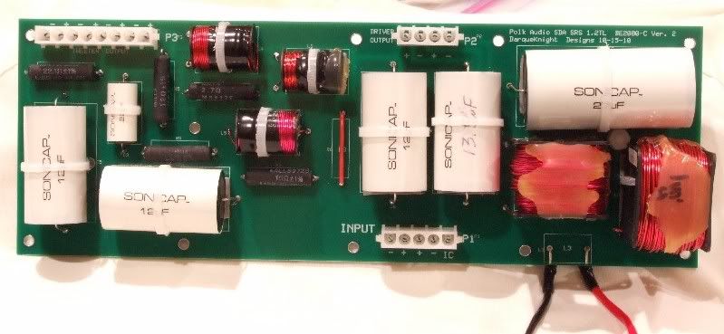
Figure 5. Custom circuit board populated.
The two wires leading from the bottom right in figure 5 connect to the large 16 mH inductor. That inductor has an diameter of 5 inches, which is too large to fit inside the cabinet opening if it were attached to the crossover cover plate.
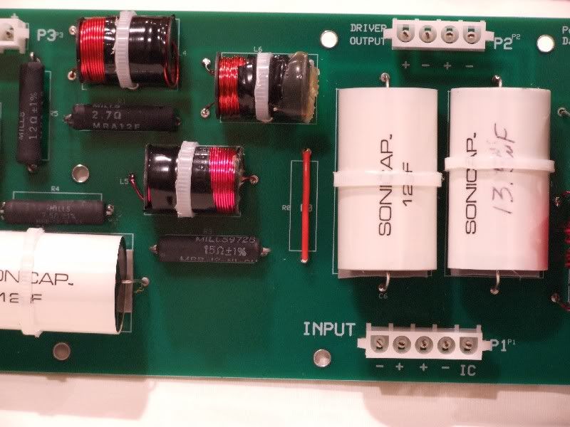
Figure 6. The red jumper is an 18 AWG solid copper wire that replaces the polyswitch.
I provided a space on the new board to replace the polyswitch with a resistor if I chose to do so. The RXE153 polyswitch has an untripped nominal DCR range of 0.12 to 0.19 ohm and a tripped DCR of 0.3 ohm. I measured the DCR's of four new RXE135 ployswitches (link). Two measured 0.16 ohm and two measured 0.17 ohm. Mills makes MRA-12 resistors in 0.1, 0.15 and 0.18 ohm.
In the future, when I am more dedicated to audio than I am now, I am going to investigate replacing the jumper with an appropriate resistor.
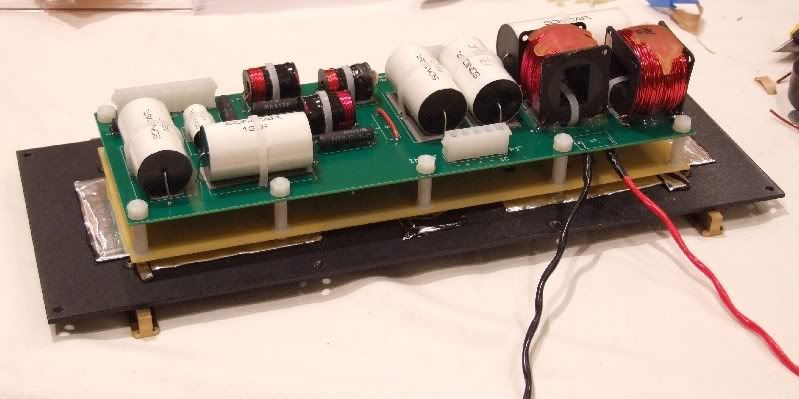
Figure 7. Populated custom board assembly.
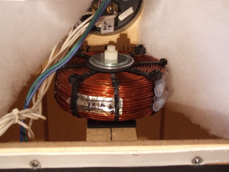
Figure 8. Installed 16 mH inductor coil.
A cabinet brace was conveniently located just under the cabinet opening. The coil is sandwiched between two 1/8" neoprene rubber pads. A plastic spool was inserted in the coil core and the coil was secured to the brace with a 3/8" diameter-5" long threaded nylon stud and nylon nuts.
Using a steel bolt through the center raised the inductance value to 18.3 mH. The metal retaining washers on top raised the inductance of the coil from 15.8 mH to 15.93 mH. The steel center bolt of the stock 16 mH coil raised the inductance from 16.25 mH to 17 mH. Aluminum bolts, washers and nuts are another option.
The upgrade coil is attached to the wires with quick disconnects and the other end of the wire is soldered to the board. After installing the 16 mH inductor, it occurred to me that it would be better to solder the wire leads directly to the inductor and then attach the wires to the board with an AMP Mate-N-Lock connector.
I am going to investigate replacing the 1 mH and 2 mH inductors in the low frequency section with North Creek inductors. The new inductors, which measure 1.25" high and 3.25" and 3.75" in diameter, will be mounted on a cabinet brace just above the cabinet opening and will be connected to the board with Mate-N-Lock connectors. Fortunately, the circuit trace arrangement is such that the board can be easily modified to accept the new connectors.
I have some concern that the much lower DCR of these signal path inductors may objectionably affect the sound balance (0.7 ohm vs. 0.21 ohm for the 1 mH inductor and 1.3 ohm vs. 0.31 ohm for the 2 mH inductor). However, if I don't like the sound I'll just go back to the stock inductors.
I did not initially plan to replace the 1 mH and 2 mH inductors with low DCR coils, but after hearing the increased image weight and enhanced SDA effect after the 16 mH was replaced, I decided to look into it.
The three stock inductors in the high frequent section will be left in place. The parallel inductor (0.4 mH) and one of the series inductors (0.4 mH) have DCR's of 0.8 and 0.9 ohm respectively. The DCR of the series inductor (0.7 mH) for the 4th tweeter is 1.9 ohm, which is in series with a 7.5 ohm resistor. I expect that replacing that inductor with a lower DCR inductor might require a redesign of the tweeter network in order to bring it back into sonic balance.
References
Gim54pod's SDA 1C Custom PCB Thread
Janne's 1.2TL Inductor Modification
Several years ago, after I had posted a thread on an SDA crossover modification, forum member Madmax mentioned the option of having custom printed circuit boards made for my SDA crossover modifications. This stayed in the back of my mind and was recently brought to the front by the recent custom printed circuit board work of forum member Gim54pod.
I have also appreciated the sharing of results by those who have replaced the inductors in their SDA's (Janne, Ben62670 and others). In addition to a custom crossover circuit board, I have replaced the large 16 mH SDA inductor in my SDA SRS 1.2TL's.
Board Layout
The custom board was designed (by me
Figure 1. Stock 1.2TL crossover circuit board and 16 mH SDA inductor on left.
Figure 2. Custom 1.2TL crossover circuit board with AMP Mate-N-Lock wiring connectors installed.
The polarity markings for the tweeter wiring connector are wrong (upper left in figure 2). I did not remember that the 1.2TL uses the same board as the crossover board as the 1.2. I did not realize the error until after a discussion about the 1.2TL circuit board with Gim54pod. The polarity markings are correct for the 1.2 but not the 1.2TL.
I also could have added another inch to the right side of the board in order to provide more space for the standoff nut between L1, L2 and C2 (figures 1 and 5). The nut is accessible with needle nose pliers. However, after assembly, I found that I would have preferred more space around the nut. Aside from this and the tweeter polarity marking error, I am very pleased with the way the board turned out.
Figure 3. Bottom of custom circuit board showing circuit traces.
Figure 4. The stock modified crossover is at top, next is the custom crossover board, at the bottom is the support board for the
main board.
The stock board was already crammed to overflowing with "normal" sized parts. The stock modified crossover with larger, higher performance capacitors was a jumbled mess. The resistors even had to be mounted on the underside of the stock board. The new board provides an orderly platform and easily facilities the replacement of parts if required or desired.
The new board measures 12" wide by 4.2 inches high. The cabinet opening for the crossover is 14-3/16" wide by 4-3/4" high. The support board prevents flexing in the long main circuit board (see figure 7).
Figure 5. Custom circuit board populated.
The two wires leading from the bottom right in figure 5 connect to the large 16 mH inductor. That inductor has an diameter of 5 inches, which is too large to fit inside the cabinet opening if it were attached to the crossover cover plate.
Figure 6. The red jumper is an 18 AWG solid copper wire that replaces the polyswitch.
I provided a space on the new board to replace the polyswitch with a resistor if I chose to do so. The RXE153 polyswitch has an untripped nominal DCR range of 0.12 to 0.19 ohm and a tripped DCR of 0.3 ohm. I measured the DCR's of four new RXE135 ployswitches (link). Two measured 0.16 ohm and two measured 0.17 ohm. Mills makes MRA-12 resistors in 0.1, 0.15 and 0.18 ohm.
In the future, when I am more dedicated to audio than I am now, I am going to investigate replacing the jumper with an appropriate resistor.
Figure 7. Populated custom board assembly.
Figure 8. Installed 16 mH inductor coil.
A cabinet brace was conveniently located just under the cabinet opening. The coil is sandwiched between two 1/8" neoprene rubber pads. A plastic spool was inserted in the coil core and the coil was secured to the brace with a 3/8" diameter-5" long threaded nylon stud and nylon nuts.
Using a steel bolt through the center raised the inductance value to 18.3 mH. The metal retaining washers on top raised the inductance of the coil from 15.8 mH to 15.93 mH. The steel center bolt of the stock 16 mH coil raised the inductance from 16.25 mH to 17 mH. Aluminum bolts, washers and nuts are another option.
The upgrade coil is attached to the wires with quick disconnects and the other end of the wire is soldered to the board. After installing the 16 mH inductor, it occurred to me that it would be better to solder the wire leads directly to the inductor and then attach the wires to the board with an AMP Mate-N-Lock connector.
I am going to investigate replacing the 1 mH and 2 mH inductors in the low frequency section with North Creek inductors. The new inductors, which measure 1.25" high and 3.25" and 3.75" in diameter, will be mounted on a cabinet brace just above the cabinet opening and will be connected to the board with Mate-N-Lock connectors. Fortunately, the circuit trace arrangement is such that the board can be easily modified to accept the new connectors.
I have some concern that the much lower DCR of these signal path inductors may objectionably affect the sound balance (0.7 ohm vs. 0.21 ohm for the 1 mH inductor and 1.3 ohm vs. 0.31 ohm for the 2 mH inductor). However, if I don't like the sound I'll just go back to the stock inductors.
I did not initially plan to replace the 1 mH and 2 mH inductors with low DCR coils, but after hearing the increased image weight and enhanced SDA effect after the 16 mH was replaced, I decided to look into it.
The three stock inductors in the high frequent section will be left in place. The parallel inductor (0.4 mH) and one of the series inductors (0.4 mH) have DCR's of 0.8 and 0.9 ohm respectively. The DCR of the series inductor (0.7 mH) for the 4th tweeter is 1.9 ohm, which is in series with a 7.5 ohm resistor. I expect that replacing that inductor with a lower DCR inductor might require a redesign of the tweeter network in order to bring it back into sonic balance.
References
Gim54pod's SDA 1C Custom PCB Thread
Janne's 1.2TL Inductor Modification
Proud and loyal citizen of the Digital Domain and Solid State Country!
Post edited by DarqueKnight on
Comments
-
Very Nice DK!!!!
Me Want.... -
Many thanks DK. Did the new inductors change tha bass any??Pio Elete Pro 520
Panamax 5400-EX
Sunfire TGP 5
Micro Seiki DD-40 - Lyra-Dorian and Denon DL-160
PS Audio GCPH phono pre
Sunfire CG 200 X 5
Sunfire CG Sig 405 X 5
OPPO BDP-83 SE
SDA SRS 1.2TL Sonicaps and Mills
Ctr CS1000p
Sur - FX1000 x 4
SUB - SVS PB2-Plus
Workkout room:
Sony Bravia XBR- 32-Inch 1080p
Onkyo TX-DS898
GFA 555
Yamaha DVD-S1800BL/SACD
Ft - SDA 1C
Not being used:
RTi 38's -4
RT55i's - 2
RT25i's -2, using other 2 in shop
LSI 15's
CSi40
PSW 404 -
Did the new inductors change tha bass any??
Yes.
Others have reported big improvements in the sound of the bass and I was expecting the same, but I only heard a modest improvement in bass detail and clarity. I felt a big change in the bass.
There was a big improvement in bass tactile sensation. When comparing the upgraded right speaker to the left speaker with the stock 16 mH coil, I could feel more vibration coming through the right armrest. I also heard more clean, defined rumble when I was in other rooms of the house.
After the large coil was replaced in both speakers, I noticed that I needed to turn the volume down a couple of notches. I also noticed that I could turn the volume down to nearly 0 (level 1), which is a whisper, and still hear details in the music. The previous comparable level was 8.Proud and loyal citizen of the Digital Domain and Solid State Country! -
-
Great looking installation!! The custom PCB makes me jealous. Looking forward to the next review of the replacement of the smaller inductors.HT/2 CH
McIntosh MX120, MC500, MC206, MEN220
polkaudio SDA SRS 1.2TL, XO, Inductor, Tweeter, Larry's rings, WBT Binding posts, Moretite and Dynamat mod. Built by Mollie Jones 27:th of February 1991, CS350-LS XO mod, LS-f/x, DSW MicroPro 4000
MIT Shotgun S3.3 Bi-wire SC, Shotgun S3.3 SC, Shotgun S3.3 Proline IC, Shotgun S3.3 IC, Shotgun S3.3 Sub cable, AVT 1 Optical IC, EXP 3 Speaker interconnect. -
Impressive. Most impressive my young padawan learner. Whoa this isn't Star Wars.DarqueKnight wrote: »Yes.
Others have reported big improvements in the sound of the bass and I was expecting the same, but I only heard a modest improvement in bass detail and clarity. I felt a big change in the bass.
There was a big improvement in bass tactile sensation. When comparing the upgraded right speaker to the left speaker with the stock 16 mH coil, I could feel more vibration coming through the right armrest. I also heard more clean, defined rumble when I was in other rooms of the house.
After the large coil was replaced in both speakers, I noticed that I needed to turn the volume down a couple of notches. I also noticed that I could turn the volume down to nearly 0 (level 1), which is a whisper, and still hear details in the music. The previous comparable level was 8.
This is strange I'm getting the same thing with my 1C's. In the bass like you I feel it more than I hear it my 1C's really dig deep when it comes to very low end bass, With the eviction control knob at 8 O'clock it's a comfortable level where you can talk to someone, at 9 O'clock still not bad but forget about talking to someone, 10 O'clock and the neighbors are banging on the walls and anything close to 11 O'clock and I'm waiting for the cops to be kicking in my front door. I didn't change the inductors on mine, Maybe it has something to do with the new PCB's I wouldn't think so but then again we are talking about crossovers and there's (as one of the guys at Polk told me) a lot of voodoo black magic going on in these SDA crossovers.
BTW: I see you stole my idea of putting pads under the caps and tying them down with zip ties.
Again DK absolutely outstanding job.“The two most important days in your life are the day you are born and the day you find out why.” ~ Mark Twain -
I didn't change the inductors on mine, Maybe it has something to do with the new PCB's I wouldn't think so but then again we are talking about crossovers and there's (as one of the guys at Polk told me) a lot of voodoo black magic going on in these SDA crossovers.
There was a part of my mind that wanted to evaluate the new PCB with the stock SDA coil in order to hear if the new board made an audible difference...but in this case I didn't yield to it.
I can foresee doing this in the future when I'm more dedicated to audio than I am now. Proud and loyal citizen of the Digital Domain and Solid State Country! -
DK...
Are you going to offer the new boards for sale to the membership?The Gear... Carver "Statement" Mono-blocks, Mcintosh C2300 Arcam AVR20, Oppo UDP-203 4K Blu-ray player, Sony XBR70x850B 4k, Polk Audio Legend L800 with height modules, L400 Center Channel Polk audio AB800 "in-wall" surrounds. Marantz MM7025 stereo amp. Simaudio Moon 680d DSD
“When once a Republic is corrupted, there is no possibility of remedying any of the growing evils but by removing the corruption and restoring its lost principles; every other correction is either useless or a new evil.”— Thomas Jefferson -
Probabally an understatement,,but it appears that the North creek inductor is well worth the investment,,eh?JC approves....he told me so. (F-1 nut)
-
Great job! Did you have ExpressPCB etch the board or did you do it yourself or other? Are you satisfied with the quality of the board and workmanship?
StanStan
Main 2ch:
Polk LSi15 (DB840 upgrade), Parasound: P/LD-1100, HCA-1000A; Denon: DVD-2910, DRM-800A; Benchmark DAC1, Monster HTS3600-MKII, Grado SR-225i; Technics SL-J2, Parasound PPH-100.
HT:
Marantz SR7010, Polk: RTA11TL (RDO198-1, XO and Damping Upgrades), S4, CS250, PSW110 , Marantz UD5005, Pioneer PL-530, Panasonic TC-P42S60
Other stuff:
Denon: DRA-835R, AVR-888, DCD-660, DRM-700A, DRR-780; Polk: S8, Monitor 5A, 5B, TSi100, RM7, PSW10 (DXi104 upgrade); Pioneer: CT-6R; Onkyo CP-1046F; Ortofon OM5E, Marantz: PM5004, CD5004, CDR-615; Parasound C/PT-600, HCA-800ii, Sony CDP-650ESD, Technics SA 5070, B&W DM601 -
As is my usual practice, I was going to discuss cost when I did my complete report. I have had several (6) inquiries about cost, therefore I think some disclosure is in order that interested persons know what they are getting into.
My boards were manufactured by ExpressPCB.com (located in Santa Barbara, CA) through their four day express service. I ordered the boards on Monday and I received them by FedEx 2nd day air on Friday.
The total cost for this project was $710.14. It would have been slightly more, but some things, such as the neoprene rubber, hookup wire and Cardas Quad Eutectic solder were in house.
The pair of main circuit boards cost $286.18
The pair of base support boards cost $132.37
The pair of 16 mH inductors cost $243.47
Screws, nuts, washers, connectors, standoffs and threaded studs cost $48.12
There was an offshore manufacturer (Futurlec) that quoted half the price of ExpressPCB, but their delivery times were almost one month.nooshinjohn wrote: »DK...
Are you going to offer the new boards for sale to the membership?
No. I think Gim54pod is in the process of setting up something like this.
My board is a custom setup for my particular pair of 1.2TL's. Some redesign would be required for a "general" model. I would also need to write an assembly manual and parts lists.george daniel wrote: »Probabally an understatement,,but it appears that the North creek inductor is well worth the investment,,eh?
Absolutely.:biggrin:Did you have ExpressPCB etch the board or did you do it yourself or other? Are you satisfied with the quality of the board and workmanship?
ExpressPCB did the total manufacturing. All I did was send them a board layout file. I am very satisfied with the quality of the board, workmanship and their quick responses to email questions.Proud and loyal citizen of the Digital Domain and Solid State Country! -
Very nice job.
Since you went through all this "trouble" to make a new board...why not going point to point and completely eliminate the PCB? Just curious._________________________________________________
***\\\\\........................... My Audio Journey ............................./////***
2008 & 2010 Football Pool WINNER
SOPAThank God for different opinions. Imagine the world if we all wanted the same woman -
I've used wafer boards and gone P2P but it's not for the impatient or highly medicated. The LSi15 tested my limits, with the SDA series being a bit more forgiving.
The collaboration between DK and Gim here looks fantastic. The board work is top notch and as usual, DK has a write-up worthy of a magazine.
I love the fact that inductors finally become cool, regardless of your stand in regards to overall results. I'm sure that I'll still be a heretic but not one xover has ever left here w/o high end inductors.CTC BBQ Amplifier, Sonic Frontiers Line3 Pre-Amplifier and Wadia 581 SACD player. Speakers? Always changing but for now, Mission Argonauts I picked up for $50 bucks, mint. -
Since you went through all this "trouble" to make a new board...why not going point to point and completely eliminate the PCB? Just curious.
PTP vs PCB is another of the "great debates" in audio. I considered PTP when Madmax first suggested a custom PC board for SDA mods.
I seriously considered PTP this time when I found out the cost of the PCB's.:frown: I have more money than time or patience, so PCB was the best choise for me, expecially when I considered the amount of time required to do a neat and professional looking PTP project. I definitely wasn't going to go from the jumbled rat's nest stock PCB to a jumbled rat's nest PTP layout. Proud and loyal citizen of the Digital Domain and Solid State Country! -
Call me a copy cat but I'm on the move Ray..
Working on the inductors now!!! -
DarqueKnight wrote: ».... the amount of time required to do a neat and professional looking PTP project.
It doesn't take that long. See?
Oh...I missed the NEAT and PROFESSIONAL part _________________________________________________
***\\\\\........................... My Audio Journey ............................./////***
2008 & 2010 Football Pool WINNER
SOPAThank God for different opinions. Imagine the world if we all wanted the same woman -
I see!!!Proud and loyal citizen of the Digital Domain and Solid State Country!
-
Great write up... need to save money...sucks.
Thanks for your work DK
what about the 5 other inductors..any thoughts/reasons to replace those? -
I noticed that you are still using what I presume is the .25 uf bypass cap on the left side of the board for T1.
Ben had mentioned that this was no longer needed with higher quality caps. What difference does this make? -
I noticed that you are still using what I presume is the .25 uf bypass cap on the left side of the board for T1.
Ben had mentioned that this was no longer needed with higher quality caps. What difference does this make?
Are you referring to C3? That's part of a contour circuit, it's not a bypass."He who fights with monsters should look to it that he himself does not become a monster. And when you gaze long into an abyss the abyss also gazes into you." Friedrich Nietzsche -
...what about the 5 other inductors..any thoughts/reasons to replace those?DarqueKnight wrote: »I am going to investigate replacing the 1 mH and 2 mH inductors in the low frequency section with North Creek inductors. The new inductors, which measure 1.25" high and 3.25" and 3.75" in diameter, will be mounted on a cabinet brace just above the cabinet opening and will be connected to the board with Mate-N-Lock connectors. Fortunately, the circuit trace arrangement is such that the board can be easily modified to accept the new connectors.
I have some concern that the much lower DCR of these signal path inductors may objectionably affect the sound balance (0.7 ohm vs. 0.21 ohm for the 1 mH inductor and 1.3 ohm vs. 0.31 ohm for the 2 mH inductor). However, if I don't like the sound I'll just go back to the stock inductors.
I did not initially plan to replace the 1 mH and 2 mH inductors with low DCR coils, but after hearing the increased image weight and enhanced SDA effect after the 16 mH was replaced, I decided to look into it.
The three stock inductors in the high frequent section will be left in place. The parallel inductor (0.4 mH) and one of the series inductors (0.4 mH) have DCR's of 0.8 and 0.9 ohm respectively. The DCR of the series inductor (0.7 mH) for the 4th tweeter is 1.9 ohm, which is in series with a 7.5 ohm resistor. I expect that replacing that inductor with a lower DCR inductor might require a redesign of the tweeter network in order to bring it back into sonic balance.I noticed that you are still using what I presume is the .25 uf bypass cap on the left side of the board for T1.
Ben had mentioned that this was no longer needed with higher quality caps. What difference does this make?
The 0.25 uF capacitor is part of the contour circuit for T1, so I left it alone. The 750 pF bypass capacitors which were in parallel with the 12 uF capacitors were removed because they were not needed. They were originally included to improve the transient response of the mylar film capacitors.
Note: Seems Face and I were typing responses to thejck at the same time. Proud and loyal citizen of the Digital Domain and Solid State Country! -
TOOLFORLIFEFAN wrote: »Call me a copy cat but I'm on the move Ray..
Working on the inductors now!!!
Your PM in-box is full.Proud and loyal citizen of the Digital Domain and Solid State Country! -
Here's a link to the pic of the crossovers that Ben did for Larry...they look the same as mine.
http://www.polkaudio.com/forums/showpost.php?p=1095569&postcount=100
There is no .25uf cap that was installed parallel to the .4mH inductor. I asked Ben about it and he said that its a bypass cap that does not need to be there because of higher quality caps.
in the crossover shcema the cap i am referring to is part of the circuit for T1 -
As mentioned, that is not a bypass cap. http://www.diyaudioandvideo.com/Calculator/Contour/Help.aspx"He who fights with monsters should look to it that he himself does not become a monster. And when you gaze long into an abyss the abyss also gazes into you." Friedrich Nietzsche
-
dang...i wonder if Ben had a reason for doing this.. What happens if the tweeter has been run without this cap.
Can I just add this cap and be fine. it get soldered onto the ends of the inductor correct?
Larry do you have the same deal with your crossovers? -
As mentioned, that is not a bypass cap. http://www.diyaudioandvideo.com/Calculator/Contour/Help.aspx
This is disappointing news because Ben did the 1.2 to 1.2 TL upgrade for my friend Jerry who purchased the speakers from CP member Speedy. I guess I'll have to go back in there and add this cap to the inductor. :frown::mad:SDA SRS 2.3TL's
Silk Audio MS-90-BT integrated tube amp
Yaqin MS-20L integrated tube amp
SDA 2B TL's -
dang...i wonder if Ben had a reason for doing this.. What happens if the tweeter has been run without this cap.
Jerry's speakers sound good. I wonder if they'll sound better after the correction? We shall see.SDA SRS 2.3TL's
Silk Audio MS-90-BT integrated tube amp
Yaqin MS-20L integrated tube amp
SDA 2B TL's -
DarqueKnight wrote: »Your PM in-box is full.
Fixed!!
I called sonicraft, and looked on the website and there is no .25uf capacitor and I guess they can't make one?? -
From DK's thread on the sonic cap review. He used the .22uF cap instead
http://www.polkaudio.com/forums/showthread.php?t=69245&highlight=sda+crossover+upgrade -
Did you ask?TOOLFORLIFEFAN wrote: »Fixed!!
I called sonicraft, and looked on the website and there is no .25uf capacitor and I guess they can't make one??"He who fights with monsters should look to it that he himself does not become a monster. And when you gaze long into an abyss the abyss also gazes into you." Friedrich Nietzsche