Studies On Residential Power Line Noise - Part 1

DarqueKnight
Posts: 6,765
Introduction
By necessity, I am a meter pontiff in my professional life. In my audio life, I prefer to use my ears as the primary measurement tool for the evaluation of good sound. Many of the desirable attributes of good sound can not be measured by currently available testing methodology and equipment. Quantities such as power, impedance, harmonic distortion, etc. can easily be measured. Other quantities, such as those responsible for imaging properties, can not be easily measured. Indeed, to my knowledge, those quantities have not yet been identified!
We do know that, generally, assuming good design and construction techniques have been followed, the more noise we remove from the signal path, the better the resulting sound staging, imaging and musical detail.
Although noise removal from the signal path must be given rigorous attention in order to achieve good sound, noise in the power delivery path must be given the same rigorous attention. Why? Because the power delivery path provides the electrical energy, the "raw material", that an audio component uses to recreate a musical event.
I wanted to obtain some data on the quality of power delivered to my two channel audio system. Over a one week period (Friday to Friday) at various times of each day, I measured the wall voltage at the dedicated audio outlets in my living room. I also measured the wall voltage at various other outlets throughout my home. During nights and early mornings (12am - 6am), the new dedicated outlets measured about 1 volt higher than the old dedicated audio and other household outlets. During the day and early evening, the dedicated audio and other household outlets measured very close to one another, with a typical difference of +/- 0.3 volts between them. A Radio Shack digital multimeter was used to measure wall voltage. During the measurement week, voltage levels ranged from a low of 118 volts (two afternoons at 5pm) to a high of 122.7 volts (two mornings at 4am). There were only two days where a voltage less than 120 volts was seen.
On the last day of the measurement week, between 4:30pm and 5:30pm, a Tektronix model TDS 2012 oscilloscope was used to generate sine wave plots and spectral plots of the line noise on the dedicated audio outlets.
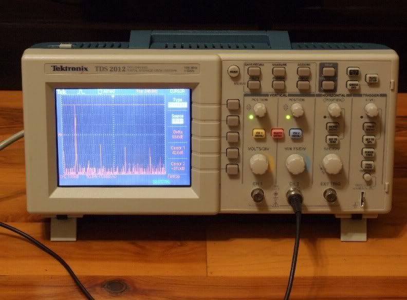
Figure 1. An oscilloscope is a handy thing to have around the house...if you want
to see the noise gremlins hiding in your wall.
Sine Wave Plot
Sine wave plots are good for letting you see how distorted (or not) the power is coming out of your wall. Spectral plots (Fast Fourier Transform plots) are good for letting you see what is causing the distortions.
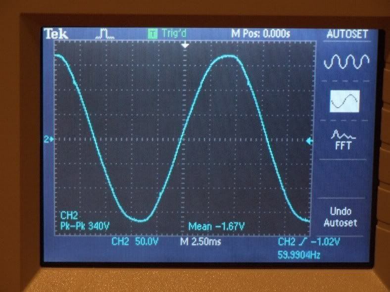
Figure 2. Power coming out of one of the original audio system dedicated outlets.
Each vertical division of the oscilloscope screen represents 50 volts. Each horizontal division represents 2.5 milliseconds. The sine wave coming out of one of the original dedicated outlets for the two channel system does not look too bad. Evidence of mild waveform distortion is seen in the "bumps" along the waveform and in the flattening near the upper and lower peaks. The oscilloscope measured a peak to peak (from the lowest point to the highest point of one sine wave) voltage of 340 volts. This corresponds to a "wall" voltage of 120.2 volts (340 volts divided by 2, then divided by the square root of 2 equals 120.2 volts). As we will see later, gremlins are quite adept at hiding behind walls and rather benign looking sine waves.
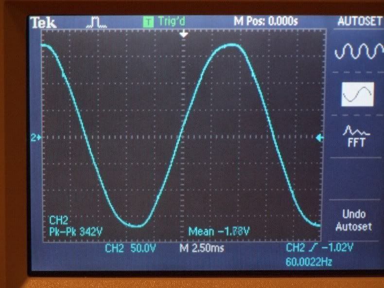
Figure 3. Sine wave plot of the power from one of the original dedicated outlets
(20A circuit) with wireless networking equipment plugged in.
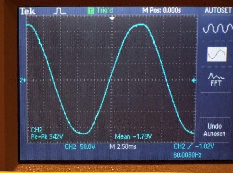
Figure 4. Sine wave plot of the power from one of the original dedicated outlets with
wireless networking equipment unplugged. Measurement was taken from a Signal
Cable MagicStrip (10 AWG).
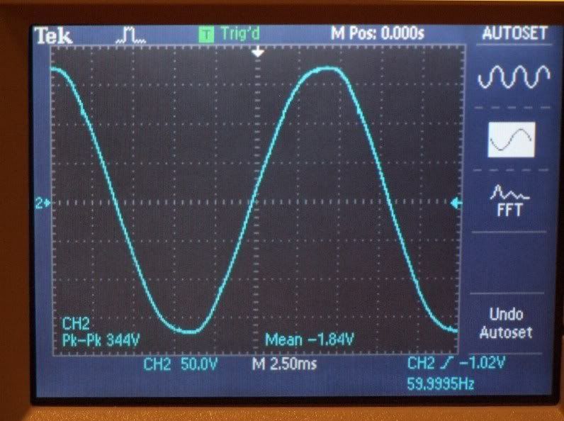
Figure 5. Power output from new dedicated 20A circuit terminated with a PS Audio
Power Port receptacle.
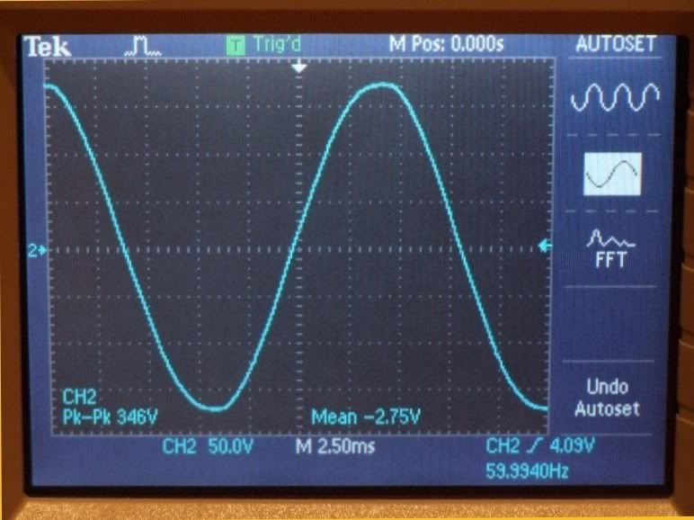
Figure 6. Power output from PS Audio Statement SC power cable connected to new
dedicated 20A circuit terminated with a PS Audio Power Port receptacle.
The sine waves for (1) one of the the original dedicated outlets (figure 2), (2) the Signal Cable MagicStrip (10 AWG) with wireless networking equipment plugged in (figure 3), (3) the Signal Cable MagicStrip with wireless networking equipment unplugged (figure 4), and (4) one of the new dedicated outlets terminated with a PS Audio Power Port receptacle (figure 5) are very similar, showing a fairly smooth sine waveform with a few distortion "bumps" along the waveform and some flattening near the upper and lower peaks. The primary differences were a slight variations in output voltage: 120.2 volts (340 volts peak to peak) from one of the original dedicated outlets, 120.9 volts (342 volts peak to peak) from the output of the Signal Cable MagicStrip connected to one of the original dedicated outlets, and 121.6 volts (344 volts peak to peak) from a Power Port outlet on one of the new dedicated circuits.
The plot in figure 6 was taken from the output of a PS Audio xStream Statement SC power cord (8 AWG). The distortion bumps are gone and the flattening near the peaks has diminished. The peaks show a more symmetrical shape on either side of the peak midpoints. This verifies PS Audio's claim that the Statement SC has a "cleaning" effect on the power signal. The voltage was raised a bit to 122.3 volts (346 volts peak to peak) due to the much lower resistance of the larger gauge cable.
Spectral Plots
Time domain plots (signal amplitude vs. time) are good for showing the net effect of noise components (those gremlins). However, residential noise gremlins are usually are not of sufficient size to cause gross distortions in the power signal coming from the wall. They usually are small in size and prefer to attack in large numbers over a large area. This makes it harder to pinpoint and eradicate them...or so they think. If we wish to find out exactly where and how big the gremlins are, we need to look at a frequency domain plot (signal power vs. frequency). Frequency domain (spectral) plots show the power contained in each frequency component of a signal.
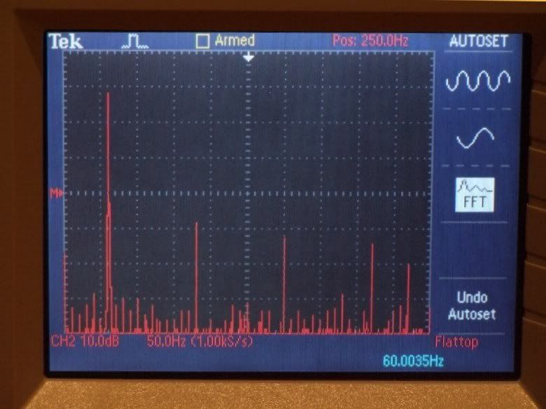
Figure 7. Spectral plot of power coming from one of the original dedicated audio outlets.
Figure 7 shows the spectral plot for the power coming from one of the original dedicated audio outlets. Each vertical division of the spectral plot represents 10 dB. Each horizontal division represents 50 Hertz. The sampling frequency used for computing the Fast Fourier Transform was 1000 samples per second. The first spike on the left edge is the DC content in the power line. The next, and largest, spike, is the 60 Hertz, 120.2 volt AC power signal. The next three large spikes are the significant odd order harmonics at 180, 300, and 420 Hertz. Note all the trash (noise frequencies...gremlins") ) grouped around the 60 Hertz spike. The spike at 60 Hertz is the only part of the signal useful in audio and video reproduction. All the other spikes, large and small, are NOISE and constitute the "noise floor". When noise is removed or attenuated, the height of the noise floor is reduced and more of the signal becomes apparent. Than is why lowering noise results in an apparently louder speaker volume, although the actual sound level remains the same.
) grouped around the 60 Hertz spike. The spike at 60 Hertz is the only part of the signal useful in audio and video reproduction. All the other spikes, large and small, are NOISE and constitute the "noise floor". When noise is removed or attenuated, the height of the noise floor is reduced and more of the signal becomes apparent. Than is why lowering noise results in an apparently louder speaker volume, although the actual sound level remains the same.
When I initially noticed the last large spike at the right, I thought it was the 8th harmonic. But then, I thought that the 8th harmonic should have been obscured in the thick layer of low magnitude line noise at the bottom of the plot. Putting the oscilloscope cursor on that spike showed it to be at 470 Hz rather than the expected 8th harmonic frequency of 480 Hz. I knew that the significant 3rd, 5th, and 7th harmonics result due to the way power is generated by the utility company. I did not know where this 470 Hz noise was coming from. After some effort, I found out that the 470 Hz frequency is one of the control tones generated by the power company in order to communicate with residential power meters. Other tones are used to control or communicate with other devices on the power grid (street lights, etc.). Surprise....some noise gremlins actually work for the power company and have a useful purpose in life.:eek:
The voltage level of each of the fundamental and harmonics is calculated this way: The vertical axis does not start at 0 dB. It starts at a reference magnitude of -27 db (0.044 volts) The fundamental 60 Hz spike has a magnitude of 68.6 dB, therefore -27 dB + 68.6 dB = 41.6 dB, which is the absolute (real) magnitude of the fundamental 60 Hz frequency. A reference voltage of 1 volt rms (Vo) is assumed. The rms voltage (voltage coming out of the wall) is calculated by Vrms=Vo x 10^(dB/20) and
for the 60 Hz frequency,
Vrms = 1 x 10^(41.6/20) = 120.2 volts.
The voltages of the DC component and the 3rd, 5th, and 7th harmonics were 0.65 volt, 2.14 volt, 0.98 volt, and 0.91 volts respectively. The 470 Hz control tone was at 0.45 volts. Although the typical voltages and energy levels of individual AC line noise components are very small compared to the main 60 Hz frequency, they collectively cause significant signal distortion which obscures detail in audio and video signals.
By necessity, I am a meter pontiff in my professional life. In my audio life, I prefer to use my ears as the primary measurement tool for the evaluation of good sound. Many of the desirable attributes of good sound can not be measured by currently available testing methodology and equipment. Quantities such as power, impedance, harmonic distortion, etc. can easily be measured. Other quantities, such as those responsible for imaging properties, can not be easily measured. Indeed, to my knowledge, those quantities have not yet been identified!
We do know that, generally, assuming good design and construction techniques have been followed, the more noise we remove from the signal path, the better the resulting sound staging, imaging and musical detail.
Although noise removal from the signal path must be given rigorous attention in order to achieve good sound, noise in the power delivery path must be given the same rigorous attention. Why? Because the power delivery path provides the electrical energy, the "raw material", that an audio component uses to recreate a musical event.
I wanted to obtain some data on the quality of power delivered to my two channel audio system. Over a one week period (Friday to Friday) at various times of each day, I measured the wall voltage at the dedicated audio outlets in my living room. I also measured the wall voltage at various other outlets throughout my home. During nights and early mornings (12am - 6am), the new dedicated outlets measured about 1 volt higher than the old dedicated audio and other household outlets. During the day and early evening, the dedicated audio and other household outlets measured very close to one another, with a typical difference of +/- 0.3 volts between them. A Radio Shack digital multimeter was used to measure wall voltage. During the measurement week, voltage levels ranged from a low of 118 volts (two afternoons at 5pm) to a high of 122.7 volts (two mornings at 4am). There were only two days where a voltage less than 120 volts was seen.
On the last day of the measurement week, between 4:30pm and 5:30pm, a Tektronix model TDS 2012 oscilloscope was used to generate sine wave plots and spectral plots of the line noise on the dedicated audio outlets.
Figure 1. An oscilloscope is a handy thing to have around the house...if you want
to see the noise gremlins hiding in your wall.
Sine Wave Plot
Sine wave plots are good for letting you see how distorted (or not) the power is coming out of your wall. Spectral plots (Fast Fourier Transform plots) are good for letting you see what is causing the distortions.
Figure 2. Power coming out of one of the original audio system dedicated outlets.
Each vertical division of the oscilloscope screen represents 50 volts. Each horizontal division represents 2.5 milliseconds. The sine wave coming out of one of the original dedicated outlets for the two channel system does not look too bad. Evidence of mild waveform distortion is seen in the "bumps" along the waveform and in the flattening near the upper and lower peaks. The oscilloscope measured a peak to peak (from the lowest point to the highest point of one sine wave) voltage of 340 volts. This corresponds to a "wall" voltage of 120.2 volts (340 volts divided by 2, then divided by the square root of 2 equals 120.2 volts). As we will see later, gremlins are quite adept at hiding behind walls and rather benign looking sine waves.
Figure 3. Sine wave plot of the power from one of the original dedicated outlets
(20A circuit) with wireless networking equipment plugged in.
Figure 4. Sine wave plot of the power from one of the original dedicated outlets with
wireless networking equipment unplugged. Measurement was taken from a Signal
Cable MagicStrip (10 AWG).
Figure 5. Power output from new dedicated 20A circuit terminated with a PS Audio
Power Port receptacle.
Figure 6. Power output from PS Audio Statement SC power cable connected to new
dedicated 20A circuit terminated with a PS Audio Power Port receptacle.
The sine waves for (1) one of the the original dedicated outlets (figure 2), (2) the Signal Cable MagicStrip (10 AWG) with wireless networking equipment plugged in (figure 3), (3) the Signal Cable MagicStrip with wireless networking equipment unplugged (figure 4), and (4) one of the new dedicated outlets terminated with a PS Audio Power Port receptacle (figure 5) are very similar, showing a fairly smooth sine waveform with a few distortion "bumps" along the waveform and some flattening near the upper and lower peaks. The primary differences were a slight variations in output voltage: 120.2 volts (340 volts peak to peak) from one of the original dedicated outlets, 120.9 volts (342 volts peak to peak) from the output of the Signal Cable MagicStrip connected to one of the original dedicated outlets, and 121.6 volts (344 volts peak to peak) from a Power Port outlet on one of the new dedicated circuits.
The plot in figure 6 was taken from the output of a PS Audio xStream Statement SC power cord (8 AWG). The distortion bumps are gone and the flattening near the peaks has diminished. The peaks show a more symmetrical shape on either side of the peak midpoints. This verifies PS Audio's claim that the Statement SC has a "cleaning" effect on the power signal. The voltage was raised a bit to 122.3 volts (346 volts peak to peak) due to the much lower resistance of the larger gauge cable.
Spectral Plots
Time domain plots (signal amplitude vs. time) are good for showing the net effect of noise components (those gremlins). However, residential noise gremlins are usually are not of sufficient size to cause gross distortions in the power signal coming from the wall. They usually are small in size and prefer to attack in large numbers over a large area. This makes it harder to pinpoint and eradicate them...or so they think. If we wish to find out exactly where and how big the gremlins are, we need to look at a frequency domain plot (signal power vs. frequency). Frequency domain (spectral) plots show the power contained in each frequency component of a signal.
Figure 7. Spectral plot of power coming from one of the original dedicated audio outlets.
Figure 7 shows the spectral plot for the power coming from one of the original dedicated audio outlets. Each vertical division of the spectral plot represents 10 dB. Each horizontal division represents 50 Hertz. The sampling frequency used for computing the Fast Fourier Transform was 1000 samples per second. The first spike on the left edge is the DC content in the power line. The next, and largest, spike, is the 60 Hertz, 120.2 volt AC power signal. The next three large spikes are the significant odd order harmonics at 180, 300, and 420 Hertz. Note all the trash (noise frequencies...gremlins
When I initially noticed the last large spike at the right, I thought it was the 8th harmonic. But then, I thought that the 8th harmonic should have been obscured in the thick layer of low magnitude line noise at the bottom of the plot. Putting the oscilloscope cursor on that spike showed it to be at 470 Hz rather than the expected 8th harmonic frequency of 480 Hz. I knew that the significant 3rd, 5th, and 7th harmonics result due to the way power is generated by the utility company. I did not know where this 470 Hz noise was coming from. After some effort, I found out that the 470 Hz frequency is one of the control tones generated by the power company in order to communicate with residential power meters. Other tones are used to control or communicate with other devices on the power grid (street lights, etc.). Surprise....some noise gremlins actually work for the power company and have a useful purpose in life.:eek:
The voltage level of each of the fundamental and harmonics is calculated this way: The vertical axis does not start at 0 dB. It starts at a reference magnitude of -27 db (0.044 volts) The fundamental 60 Hz spike has a magnitude of 68.6 dB, therefore -27 dB + 68.6 dB = 41.6 dB, which is the absolute (real) magnitude of the fundamental 60 Hz frequency. A reference voltage of 1 volt rms (Vo) is assumed. The rms voltage (voltage coming out of the wall) is calculated by Vrms=Vo x 10^(dB/20) and
for the 60 Hz frequency,
Vrms = 1 x 10^(41.6/20) = 120.2 volts.
The voltages of the DC component and the 3rd, 5th, and 7th harmonics were 0.65 volt, 2.14 volt, 0.98 volt, and 0.91 volts respectively. The 470 Hz control tone was at 0.45 volts. Although the typical voltages and energy levels of individual AC line noise components are very small compared to the main 60 Hz frequency, they collectively cause significant signal distortion which obscures detail in audio and video signals.
Proud and loyal citizen of the Digital Domain and Solid State Country!
Post edited by DarqueKnight on
Comments
-
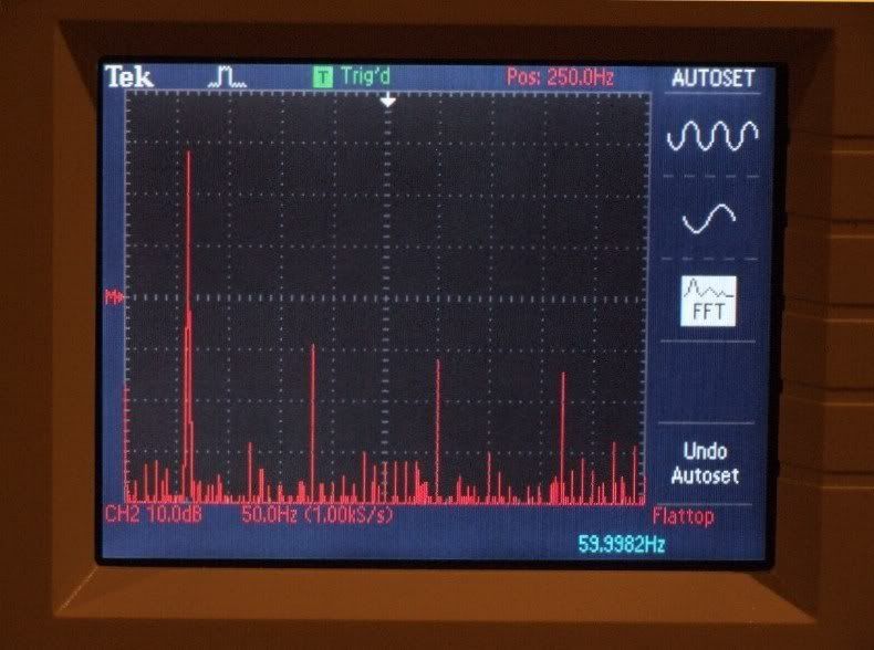
Figure 8. Power output from an open receptacle of the Signal Cable MagicStrip with
wireless networking equipment plugged in.
Figure 8 is the spectral plot of the power coming from a Signal Cable four outlet MagicStrip plugged into the outlet whose power spectral chart is shown in figure 7. A cable modem, router, and access point are plugged into the strip's other three outlets. Comparing figures 7 and 8, a reduction in noise frequencies, with the exception of the odd order harmonics, is seen. In particular, notice the reduction in the power of noise frequencies near 60 Hertz.:)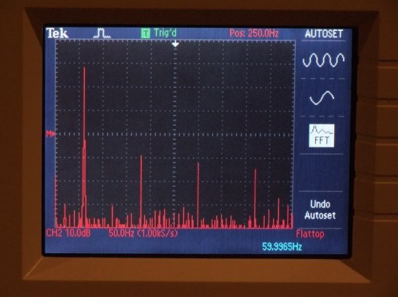
Figure 9. Power output from an open receptacle of the Signal Cable MagicStrip with
wireless networking equipment unplugged.
Figure 9 is the spectral plot of the power coming from the Signal Cable four outlet MagicStrip with the modem, router, and access point unplugged. In addition to lower noise overall (again with the exception of the odd order harmonics), there is a reduction of 2 to 4 dB in the power of the even order harmonics. The 470 Hz control tone was attenuated by 7 dB.:)
I mentioned in another recent post that, back when my audio and wireless networking equipment were all sharing the same circuit, I could hear an improvement in sound quality when the networking equipment was unplugged. This was manifested as a slight increase in detail from the middle midrange and up. Put another way, a slight veiling was removed when the networking equipment was unplugged. They, and their associated gremlins, now have their own dedicated outlet.:)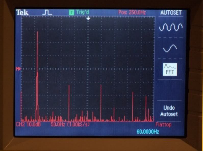
Figure 10. Spectral plot of one of the new dedicated 20A circuits terminated with a
PS Audio Power Port receptacle.
Figure 10 is a spectral plot of the power coming from one of the new dedicated 20A circuits terminated with a PS Audio Power Port receptacle. The plot shows further reductions in noise power over that provided by the Signal Cable MagicStrip. The 2nd, 3rd 4th, 6th, and 7th harmonics were reduced in power by 2 to 3 dB. The pesky 470 Hz control tone popped back up by 7 dB.:(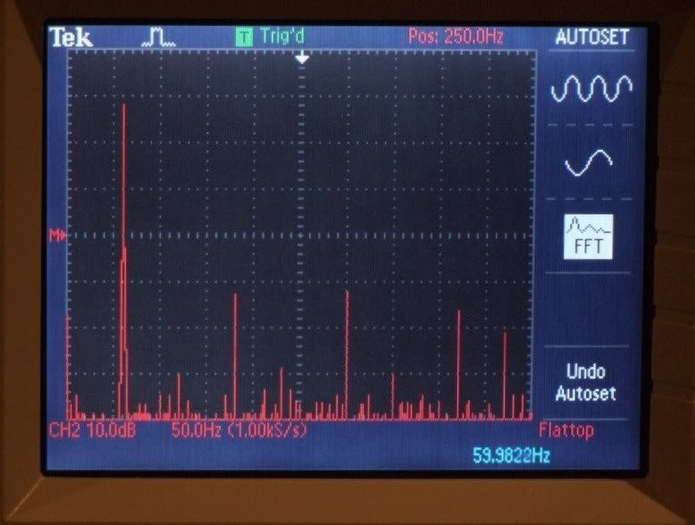
Figure 11. Spectral plot of the power coming from a PS Audio xStream Statement
SC power cord plugged into the PS Audio Power Port receptacle. No wonder you
make Such Good Sound.
Figure 11 shows the spectral plot of the power coming from a PS Audio xStream Statement SC power cord plugged into the PS Audio Power Port receptacle whose spectral plot is given in figure 10. The magnitudes of the fundamental frequency and the 3rd, 5th, 6th, 7th harmonics and the 470 Hz control tone remains unchanged. The 2nd and 4th harmonic magnitudes rose 2 and 3 dB's respectively. Most noticeable is the further reduction in the power of noise frequencies around the fundamental 60 Hertz frequency and its harmonics.
Compare figure 11 to figure 7. While the gremlins have not been totally eradicated, they have been significantly beat down.:)
Conclusion
Several years ago, I verified with my ears the good effects that a quality power cord can have on audio and video signal quality. Now, I have verified with quantitative measurements what my ears have been telling me all along. I now have a deeper understanding of what is going on in power lines and power cables.
Further Study
Based on these quantitative results and careful listening, I have decided that an investment in further power conditioning might be justified. I am currently researching options in passive and regenerative power conditioning. Future reports in this series will discuss my results in this area and in other areas of quantitative residential power line noise evaluation.
What Confucius said over 2000 years ago is still true today: The more clean power and clean sound you get, the more you want.;)*
References
1. Review of Magic Power Digital Reference Power Cable
2. Review of Signal Cable MagicPower Cords
3. Review of PS Audio xStream Statement SC Power Cords, Juice Bar II, Power Ports
* In your case, I think that what Gordon Gekko said over 20 years ago is more appropriate. Proud and loyal citizen of the Digital Domain and Solid State Country!
 -
Space reserved for follow up.Proud and loyal citizen of the Digital Domain and Solid State Country!
-
Have you seen the PS Audio DVD that some stores are giving away called "Coal to Coltrane - A History of Power"? Not nearly as scientific as your research above, but an interesting watch just the same. It has some funny interviews with some of the name brand audio journalists that are pretty amusing. If you PM me your addy I'll send you my copy to watch.DKG999
HT System: LSi9, LSiCx2, LSiFX, LSi7, SVS 20-39 PC+, B&K 507.s2 AVR, B&K Ref 125.2, Tripplite LCR-2400, Cambridge 650BD, Signal Cable PC/SC, BJC IC, Samsung 55" LED
Music System: Magnepan 1.6QR, SVS SB12+, ARC pre, Parasound HCA1500 vertically bi-amped, Jolida CDP, Pro-Ject RM5.1SE TT, Pro-Ject TubeBox SE phono pre, SBT, PS Audio DLIII DAC -
Thanks DKG. I ordered a copy through the PS Audio website when they first became available.Proud and loyal citizen of the Digital Domain and Solid State Country!
-
Hmmmm, proof that your ears don't lie? Whooda' thunk?
Very nice! Very nice!~ In search of accurate reproduction of music. Real sound is my reference and while perfection may not be attainable? If I chase it, I might just catch excellence. ~ -
Now how about some power factor measurements?:D"The legitimate powers of government extend to such acts only as are injurious to others. But it does me no injury for my neighbour to say there are twenty gods, or no god. It neither picks my pocket nor breaks my leg." --Thomas Jefferson
-
Nice Tektronix model TDS 2012 oscilloscope ... thanks for all the figures.
-
sucks2beme wrote: »Now how about some power factor measurements?:D
I agree. I'd be interested to see if you can hear the difference between, leading, lagging, and unity (if your utility keeps it regulated that close like my employer).
I don't think I have quite the golden ears of some around here, but I do have very good eyes. I noticed an immediate difference on my plasma after plugging it into a Belkin PureAV unit. I initially left my amps plugged in the wall when I got the unit, then I tried plugging the tweeter amp into the unit, then I plugged both amps in and couldn't hear much difference, so I figured even I couldn't hear the difference, but I could see it, then it was something I should do.
WesLink: http://polkarmy.com/forums
Sony 75" Bravia 4K | Polk Audio SDA-SRS's (w/RDO's & Vampire Posts) + SVS PC+ 25-31 | AudioQuest Granite (mids) + BWA Silver (highs) | Cary Audio CAD-200 | Signal Cable Silver Resolution XLR's | Rotel Michi P5 | Signal Cable Silver Resolution XLR's | Cambridge Audio azur 840C--Wadia 170i + iPod jammed w/ lossless audio--Oppo 970 | Pure|AV PF31d -
How about a little help here for those (me) not fully understanding of this whole clean/dirty power stuff.
Aren't there filter caps and such inside amps and other electronics designed to clean up and filter the power entering said units? Also, isn't the power inside the amp changed from AC to DC by the transformer and then taken from there by the power regulator? So how does external filtering come into play if it's going to be run through the units transformers, filters and other power circuits?
Thanks!Driver carries only 20 dollars in ammunition
Pedestrians have the right of way, unless they are in the way -
There is some information in the introduction of the report's 3rd reference that you may find useful.Proud and loyal citizen of the Digital Domain and Solid State Country!
-
Awesome Raife!
Where's William and John when we need them most?:D -
Oooooo so techyHT setup
Panasonic 50" TH-50PZ80U
Denon DBP-1610
Monster HTS 1650
Carver A400X :cool:
MIT Exp 3 Speaker Wire
Kef 104/2
URC MX-780 Remote
Sonos Play 1
Living Room
63 inch Samsung PN63C800YF
Polk Surroundbar 3000
Samsung BD-C7900 -
Very interesting Raife. Has PS Audio seen these plots? It certainly helps prove their point. Thanks for your investment of time and interest in this subject. Many people overlook their power cords and power source, and some frankly poo paw it. Great writeup!
I'm watching for your followup on the power conditioning.Carl -
Seeing is believing
")
Speakers
Carver Amazing Fronts
CS400i Center
RT800i's Rears
Sub Paradigm Servo 15
Electronics
Conrad Johnson PV-5 pre-amp
Parasound Halo A23
Pioneer 84TXSi AVR
Pioneer 79Avi DVD
Sony CX400 CD changer
Panasonic 42-PX60U Plasma
WMC Win7 32bit HD DVR -
Perhaps you can do some similar measurements on less expensive power upgrade options. Such as a higher end model recepticle ($10??) from Home Depot or Lowes. Or perhaps with just an upgraded quality , but not boutique, power cables.
I can see the differences the improvements make in the scope, but what's the value of cost vs improvement? Specifically how much of an improvement are the boutique cables vs the higher quality big box store type?
Were all your measurements (of the various outlets) from outlets in the same phase, different or not noted? Might it make a difference?____________________
This post is a natural product. The slight variations in spelling and grammar enhance its individual character and beauty and in no way are to be considered flaws or defects.
HT:Onkyo 805, Emotiva XPA-5, Mitsu 52" 1080p DLP / polkaudio RTi12, CSIa6, FXi3, uPro4K
2-chnl : Pio DV-46AV (SACD), Dodd ELP, Emotiva XPA-1s, XPA-2, Odyssey Khartago, LSi9, SDA-SRS 2 :cool:, SB Duet, MSB & Monarchy DACs, Yamaha PX3 TT, SAE Tuner...
Pool: Atrium 60's/45's -
Perhaps you can do some similar measurements on less expensive power upgrade options.
I did: Signal Cable.;)
You might also be interested in reading a report I wrote on some speaker cable I made from Home Depot 6 gauge wire here. At the end of this review is a chart listing the sonic differences between the Home Depot cable and three higher cost cables.Or perhaps with just an upgraded quality , but not boutique, power cables.
Sure. I could do that.:)I can see the differences the improvements make in the scope, but what's the value of cost vs improvement? Specifically how much of an improvement are the boutique cables vs the higher quality big box store type?
I would refer you to some of my previous cable reviews here on the forum. Most, if not all, of them include a discussion of price vs. performance. This report included some comparison between the PS Audio Statement power cable and the Signal Cable MagicPower cable. The quantitative performance differences between the two are discussed in this report. I discussed price differences in my review of the Statement cables, which is referenced in the report.Were all your measurements (of the various outlets) from outlets in the same phase, different or not noted? Might it make a difference?
The new dedicated outlets are on different voltage legs (phases). The two original dedicated outlets are on the same phase as the left new dedicated outlet. The household outlets, regardless of phase, measured very close to each other. There were some small differences among the typical household outlets and the original and dedicated outlets at certain times of the day, as noted in the report.Proud and loyal citizen of the Digital Domain and Solid State Country! -
Proud and loyal citizen of the Digital Domain and Solid State Country!
-
somehow I sense a small disturbance on the radar, anti hifi audio insurgent seems to be uncloaking.:)
nice job Raife.
RT1 -
So we have proved that cables do make a difference
 Let the uncloaking of the anti hi-fi insurgents begin. Shields up and phasors on stun, make it so #1. DKG999
HT System: LSi9, LSiCx2, LSiFX, LSi7, SVS 20-39 PC+, B&K 507.s2 AVR, B&K Ref 125.2, Tripplite LCR-2400, Cambridge 650BD, Signal Cable PC/SC, BJC IC, Samsung 55" LED
Music System: Magnepan 1.6QR, SVS SB12+, ARC pre, Parasound HCA1500 vertically bi-amped, Jolida CDP, Pro-Ject RM5.1SE TT, Pro-Ject TubeBox SE phono pre, SBT, PS Audio DLIII DAC -
Bottom line-dedicated outlets are a good idea. Both for noise and current draw.
Even if you don't believe in cables, there's no end of proof that certain household
devices shouldn't be on the same breaker as your 2 channel or HT. If you're gonna
spend money, run dedicated power from the breaker box to your audio setup.
Start there, then play with power cables. I suspect many have started with the
cables, and then passed judgement. Like always, fancy cables should come after
the rest has been upgraded!"The legitimate powers of government extend to such acts only as are injurious to others. But it does me no injury for my neighbour to say there are twenty gods, or no god. It neither picks my pocket nor breaks my leg." --Thomas Jefferson -
Has anyone tested the power inside a component (after its internal filtering) for differences before and after supply line upgrades? Would be interesting to see the changes at that point as well.Driver carries only 20 dollars in ammunition
Pedestrians have the right of way, unless they are in the way -
What your findings on line noise and dedicated power outputs, would you put any weight to what an Audiophile AC in-wall cable could add to this?
http://www.dedicatedaudio.com/inc/sdetail/14230
Speakers
Carver Amazing Fronts
CS400i Center
RT800i's Rears
Sub Paradigm Servo 15
Electronics
Conrad Johnson PV-5 pre-amp
Parasound Halo A23
Pioneer 84TXSi AVR
Pioneer 79Avi DVD
Sony CX400 CD changer
Panasonic 42-PX60U Plasma
WMC Win7 32bit HD DVR -
I think anything that lowers impediment to current flow and lowers noise is a good thing. I would definitely consider a better quality in-wall wire, I don't know if I'd pay nearly $12 a foot for it though. Romex 10 gauge is about $1 a foot. I would have to see some compelling data to justify the price of that Carda$ in-wall wire. I would need two 80 foot run$ (2 x 80 x $11.50 = $1840). I think better power cables and power conditioning gear might be a better investment than boutique in-wall wire.
Investing in expensive inwall wire is much more of a committment than investing in expensive component cables. Cables can be purchased on the used market at fractions of their retail price and then sold if they don't work out. New cables can be returned to the store if they don't work out. How are you going to feel if you spend all that time running the Cardas 10 gauge through the wall and you find that it does not sound any better than 10 gauge Romex?
My new dedicated 20A outlets were wired with Romex Simpull E18679 12 AWG wire.
I plan to rewire with 10 AWG wire in the future. My reason for not installing 10 AWG Romex in the first place was because:
1. I wanted to compare the new dedicated 20A, 12 AWG circuits terminated with PS Audio Power Port outlets to the original dedicated 20A, 12 AWG circuit terminated with residential grade outlets.
2. I want to be able to compare listening and measurement data between the new dedicated circuits wired with 12 AWG and then 10 AWG wire. I always like to know the degree of improvement a change makes.:) I am going to upgrade the power delivery to my home theater system in the near future. The results from my 2 channel experimentation will provide a degree of confidence regarding what to use for that upgrade.
It would have only cost a total of $135 to wire both new 20A circuits with 10 AWG instead of 12 AWG. Since all the holes in the wall studs are drilled, it will be a simple matter of running new wire from the breaker panel to the outlets when I decide to install the 10 gauge wire.Proud and loyal citizen of the Digital Domain and Solid State Country! -
Thank you for that very detailed and very interesting read. As usual your posts are some of the most informative on this site, I learn a lot from them.AVR: Elite VSX-21TXH
Amplifier: B&K 7250 Series ii
Misc: Velodyne SMS-1
Mains: RTi-10
Center: CSi-5
Rear: Boston DSi460
Sub: SVS PC-Ultra
TV: Panasonic TC-P58V10
DVD: Panasonic DMP-BD60K -
Fascinating and captivating read, Darque One. You are an inspiring hobbyist. I think you must talk to Tesla on, at least, an intermittent basis.
-
DarqueKnight wrote: »Romex 10 gauge is about $1 a foot. I would have to see some compelling data to justify the price of that Carda$ in-wall wire. I would need two 80 foot run$ (2 x 80 x $11.50 = $1840). I think better power cables and power conditioning gear might be a better investment than boutique in-wall wire.
I agree, but with such nice test equipment I would if it must be tested. Just maybe a cord made up to simulate what the wire could do. Maybe a small length of say 5 to 10' would show if such an investment is worth the price.
Steve
Speakers
Carver Amazing Fronts
CS400i Center
RT800i's Rears
Sub Paradigm Servo 15
Electronics
Conrad Johnson PV-5 pre-amp
Parasound Halo A23
Pioneer 84TXSi AVR
Pioneer 79Avi DVD
Sony CX400 CD changer
Panasonic 42-PX60U Plasma
WMC Win7 32bit HD DVR -
DarqueKnight wrote: »...
The results from my 2 channel experimentation will provide a degree of confidence regarding what to use for that upgrade.
I like your methodology. Kudos. :cool:____________________
This post is a natural product. The slight variations in spelling and grammar enhance its individual character and beauty and in no way are to be considered flaws or defects.
HT:Onkyo 805, Emotiva XPA-5, Mitsu 52" 1080p DLP / polkaudio RTi12, CSIa6, FXi3, uPro4K
2-chnl : Pio DV-46AV (SACD), Dodd ELP, Emotiva XPA-1s, XPA-2, Odyssey Khartago, LSi9, SDA-SRS 2 :cool:, SB Duet, MSB & Monarchy DACs, Yamaha PX3 TT, SAE Tuner...
Pool: Atrium 60's/45's -
In going from 12ga. to 10ga. are you also going from a 20amp to a 30amp breaker or fuse? Is it possible that a 30amp breaker wouldn't "trip" from a short in your rig, at a draw that would start a fire in your equipment ? Just curious ! gdb
-
I will be using 10 gauge wire on the same 20A breaker.Proud and loyal citizen of the Digital Domain and Solid State Country!
-
Has anyone tested the power inside a component (after its internal filtering) for differences before and after supply line upgrades? Would be interesting to see the changes at that point as well.
Even better would be some measurements at the analog outputs.