Polk rti a7 crossover problem
Options

emrser
Posts: 8
Hi , I usually used for polk audio rti a7 speakers for 10+ years the crossover of my right speaker's resistance burned and get repaired , so therefore sound tone differeances occured about the treble and mid frequencies ( ı thinkThe upper-mids and highs sound more subdued compared to the other one.) , ı need to make it equal with the left and right speakers , so ı observed the schematic of rti a7 and crossovers , so ı need to ask some questions about that
İf ı change my right my speaker's crossover's resistance and capacitor to new and same value ( same tolerance , same uf , ohm etc ) with the different brand (just like jantzen or dyton ) may ı get the equality of sound in contrast with the left speaker which is have fabrication crossover ? (Yes the resistance burned but it may damaged on the capacitors and resistance on the mid and treble ) Or there is no make it equality ? Because the fabrication crossovers res, and cap may have some different esp values even if its the same tolerance and electronic values ? , Or do ı have to both changed ?
İf ı change my right my speaker's crossover's resistance and capacitor to new and same value ( same tolerance , same uf , ohm etc ) with the different brand (just like jantzen or dyton ) may ı get the equality of sound in contrast with the left speaker which is have fabrication crossover ? (Yes the resistance burned but it may damaged on the capacitors and resistance on the mid and treble ) Or there is no make it equality ? Because the fabrication crossovers res, and cap may have some different esp values even if its the same tolerance and electronic values ? , Or do ı have to both changed ?
Comments
-
The only way to make sure is to measure all the components. An LCR meter would work well. Depending upon the circuit you may or may not have to lift one lead (desolder) of the component to check.
Of course the way to make sure would be to replace all the components with like values but on small boards that can require some creativity, especially if you are wanting to upgrade from electrolytic capacitors to film types which are much larger in size.
If you have good ears and an audio chain that is highly resolving you will hear the difference between different components IMO (especially capacitors) so I wouldn't use different ones from L to R crossovers.
I'm not vouching for this one, but here's an LCR meter:
https://www.amazon.com/Proster-Multimeter-Capacitance-Resistance-Inductance/dp/B071WNNYQT/ref=sr_1_5_sspaGeorge / NJ
Polk 7B main speakers, std. mods+ (1979, orig owner)
Martin Logan Dynamo sub w/6ft 14awg Power Cord
Onkyo A-8017 integrated
Logitech Squeezebox Touch Streamer w/EDO applet
iFi nano iDSD DAC
iPurifier3
iDefender w/ iPower PS
Custom Steve Wilson 1m UPOCC Interconnect
iFi Mercury 0.5m OFHC continuous cast copper USB cable
Custom Ribbon Speaker Cables, 5ft long, 4N Copper, 14awg, ultra low inductance
Custom Vibration Isolation Speaker Stands and Sub Platform -
Gardenstater wrote: »The only way to make sure is to measure all the components. An LCR meter would work well. Depending upon the circuit you may or may not have to lift one lead (desolder) of the component to check.
Of course the way to make sure would be to replace all the components with like values but on small boards that can require some creativity, especially if you are wanting to upgrade from electrolytic capacitors to film types which are much larger in size.
If you have good ears and an audio chain that is highly resolving you will hear the difference between different components IMO (especially capacitors) so I wouldn't use different ones from L to R crossovers.
I'm not vouching for this one, but here's an LCR meter:
https://www.amazon.com/Proster-Multimeter-Capacitance-Resistance-Inductance/dp/B071WNNYQT/ref=sr_1_5_sspa
First of all , thank you for your interest . Unfortunately ı dont have any choice to remove any components from the circuit because i can make them damage or ruin , so it is required to extract to components from the circuit to check exact result with the help of LCR meter , therefore ı created thread about that , ı will not choice the approximate value of those capacitor and resistances , ı will choice the exact same values of replacing the capacitors and resistance , but ı cant find the exact brand of the elements , so it will the same value but different brand , so it menas different brand means the different sound tonage ? I need to know that , but if we cant know this without the measurement , In that case, this could mean that the contraction is narrowing the circle. -
Here's a guy who goes into great detail of his own perceptions of the audible differences between different capacitors: https://www.humblehomemadehifi.com/Cap.html
I would take the opportunity to upgrade to a higher quality brand and type, so in other words, I wouldn't even bother trying to find the ones that Polk used; they are decent quality but to satisfy a price point. You can do much much better.
Don't put any new components in any position on the L board without making the exact same change in the R board is what I'm saying. Brand, Model, and Value.
Basic hierarchy of increasing (from L to R) Sound Quality:
Electrolytics >> Audio Grade Electrolytics >> Mylar Metalized Film >> Polypropylene Metalized Film >> Metal Foil Caps
George / NJ
Polk 7B main speakers, std. mods+ (1979, orig owner)
Martin Logan Dynamo sub w/6ft 14awg Power Cord
Onkyo A-8017 integrated
Logitech Squeezebox Touch Streamer w/EDO applet
iFi nano iDSD DAC
iPurifier3
iDefender w/ iPower PS
Custom Steve Wilson 1m UPOCC Interconnect
iFi Mercury 0.5m OFHC continuous cast copper USB cable
Custom Ribbon Speaker Cables, 5ft long, 4N Copper, 14awg, ultra low inductance
Custom Vibration Isolation Speaker Stands and Sub Platform -
I am hoping you have the crossover schematic. If not, the PDF is located here: https://forum.polkaudio.com/discussion/202480/rti-a-series-crossovers#latest
Regarding components, Mills MRA 12W are generally a standard for crossover resistors. Some will argue that the Dayton non-inductive wirewound resistors from Partsexpress are close in quality, but significantly less expensive. Either will be better than the original sandcast resistors. I would use decent capacitors in the tweeter circuit. Jantzen Cross Caps, or Clarity Cap PX at a minimum. Size is a factor on the larger capacitors in the woofer section, and since they are shunt caps, they don't have as much of an effect on sound quality. Non-polar electrolytic is what the factory came with and using new equivalents will give you similar sound to what you had.
One thing to look out for, is the inductors could have been damaged by overcurrent. You'll need an LCR meter to measure those. An out of spec inductor can make a big difference in sound between channels. I've had it happen to me on a vintage set of Mirage M3.
-
I am hoping you have the crossover schematic. If not, the PDF is located here: https://forum.polkaudio.com/discussion/202480/rti-a-series-crossovers#latest
Regarding components, Mills MRA 12W are generally a standard for crossover resistors. Some will argue that the Dayton non-inductive wirewound resistors from Partsexpress are close in quality, but significantly less expensive. Either will be better than the original sandcast resistors. I would use decent capacitors in the tweeter circuit. Jantzen Cross Caps, or Clarity Cap PX at a minimum. Size is a factor on the larger capacitors in the woofer section, and since they are shunt caps, they don't have as much of an effect on sound quality. Non-polar electrolytic is what the factory came with and using new equivalents will give you similar sound to what you had.
One thing to look out for, is the inductors could have been damaged by overcurrent. You'll need an LCR meter to measure those. An out of spec inductor can make a big difference in sound between channels. I've had it happen to me on a vintage set of Mirage M3.
Thank you for your interest @Gardenstater And thank you, too. , ı emailed to guy who has it own topic which is you have sent before and he said that even if the values and tolerances are the same replace with a new capacitors and resistances , there will not be equality about the stereo scene , so he recommended the both side changed just like you have said
@billbillw actually ı just wanted to make it equal stereo tonage related to both side voice and ı wanted to protect polk audio rti a7' sound characteristic and ı dont wanted to upgrade these speakers , tehrefore ı thought that if ı changed the elements of the crossover replace with in same values of elements provide the protecting of the rti a7's sound characteristic , The schematic for my A7 is included in the topic you sent.There is a 8.2uf y.c brand 50v eletrolyc capacitor and 2.4ohm %5 tolerance resistor on the treble side , Moreover there is a 18uf y.c brand 50v capacitor and resistance on the mid side , I wanted to replace the components with ones having the exact same values—albeit from a different brand - thinking that, as you suggested, I could achieve the same character and sound rather than just something "similar." I hoped to do this without touching the other original speaker, but it seems things might work a bit differently in electronics. What approach did you take to ensure consistency?
-
So there are possibilities here of components being out of spec and there is also the possibility of components that have been damaged.
I'm not trying to be curt but if you aren't testin' you're guessin'.
You are saying you don't want to upgrade and, frankly, that would be very limited in feasibility anyways if you wanted to go with film capacitors and air core inductors. They designed this board to be very compact and used lots of axial radial mount electrolytic capacitors with the only film caps being two small mylar 0.47uF bypass caps. There are also mostly iron core inductors which are much more compact than air cores.
Can you maybe ask more detailed questions? There may be forum members that have some experience with high quality electrolytic capacitors with low dissipation factors (DF) and esr's (effective series resistance) that they could recommend but a lot will depend upon your location and their availability there.
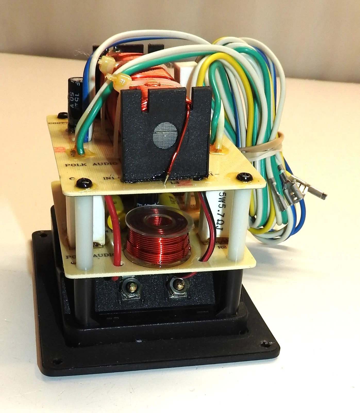
Here's what the crossover looks like, as you probably know but people reading this thread don't all know:
https://www.ebay.com/itm/407140627114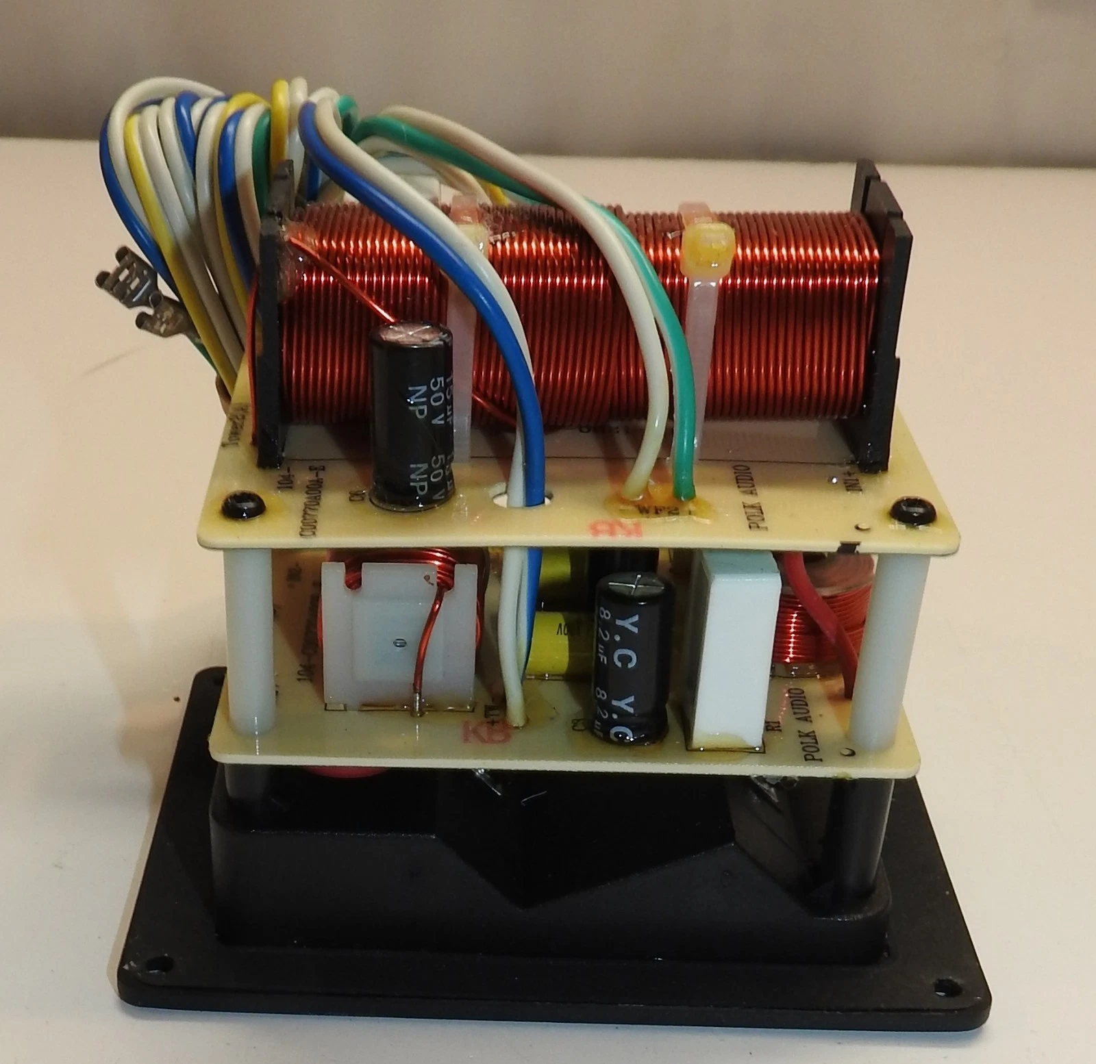
George / NJ
Polk 7B main speakers, std. mods+ (1979, orig owner)
Martin Logan Dynamo sub w/6ft 14awg Power Cord
Onkyo A-8017 integrated
Logitech Squeezebox Touch Streamer w/EDO applet
iFi nano iDSD DAC
iPurifier3
iDefender w/ iPower PS
Custom Steve Wilson 1m UPOCC Interconnect
iFi Mercury 0.5m OFHC continuous cast copper USB cable
Custom Ribbon Speaker Cables, 5ft long, 4N Copper, 14awg, ultra low inductance
Custom Vibration Isolation Speaker Stands and Sub Platform -
@Gardenstater I have personally examined the circuit board, both in terms of its schematic and its individual components—yes, it is the board shown in the photo. While the only way to be 100% certain would be to remove every component and test them one by one, that is beyond my current capabilities. Based on my own assessment—supported by input from an AI (to which I had sent a photo of the board)—and the fact that the coils appear to be in good condition, I suspect the issue lies with the capacitors and resistors. The sound quality problem, specifically affecting the mid and high frequencies, points toward these components; the AI also suggested focusing primarily on the capacitors, noting that Mylar capacitors, in particular, rarely fail.
For instance, the circuit shows that an 8.2 µF capacitor—paired with a bypass capacitor—and a 2.4-ohm resistor are used for the mid-range section. I reasoned that by using components with the exact same values—an 8.2 µF capacitor and a 2.4-ohm resistor from the brand Jantzen—I could closely replicate the circuit design implemented by the Polk engineers and achieve the same sonic characteristics.
Of course, even without taking any measurements, the fact that the artificial intelligence specifically highlighted the mid and treble sections—where I’ve been experiencing a "veiled" or "muffled" sound—suggests that replacing the components in these parts could largely resolve the issue. Even if the coils appear to be in good condition, their actual values might have drifted, making it logical to simply purchase a new crossover. This is especially true considering that, to perform accurate measurements, one would have to desolder every single component anyway; if I were to replace the capacitors and resistors with new ones of the same nominal values but still fail to achieve the desired sound character, then buying a new crossover would definitely be the most sensible approach.
I hope this explanation is clear and that my message didn't come across as annoying. -
Coils can look normal and be vastly off from spec if they were exposed to excess current. If you are going to DIY a repair, you really need to have the tools. Otherwise, you are wasting your time just visually examining things and relying on AI. Don't trust AI for things like this. Visual exams won't tell you anything unless there is a burnt part. In my case, I had a coil that was way off and didn't filter the midrange out of a woofer. It looked exactly the same as the one that was in spec.
-
No annoyance at all. I looked at the crossover and you shouldn't have to remove any components to test them all. The drivers have fastons and can be disconnected. You are aided by the fact that capacitors don't pass DC current which is what the continuity testing for shorts and opens will involve. The speaker cables should of course not be in place. The only thing you might have to do is desolder one lead on each of the bypass mylar caps, in order to test both parallel caps independently. To avoid heat damage just clip a small hemostat onto the lead and that will help with pulling it out as well. Check resistances, continuity, inductances and capacitance with an LCR meter. You can even get ones that do ESR and DF.
You can probe the board on the trace side by placing the probes of the meter on the solder pads.
I looked a bit for radial bipolar electrolytic caps on the audio sites and there isn't much but that's getting ahead of ourselves.
I have to wonder why the AI "thinks" that the 10.0uf tweeter capacitor is not subject to damage. The current would be greater through it than the 8.2 uf.
I see from reviews that the crossover frequencies are 2.7 kHz and 125 Hz, both at 12 dB per octave fwiw.
PS: Another option is to buy that crossover that I posted the link to but that is a US listing and I'm guessing you are elsewhere. Here's another one that is even cheaper:
https://www.ebay.com/itm/137853249205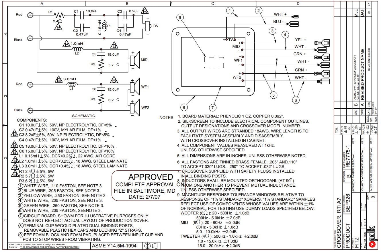
George / NJ
Polk 7B main speakers, std. mods+ (1979, orig owner)
Martin Logan Dynamo sub w/6ft 14awg Power Cord
Onkyo A-8017 integrated
Logitech Squeezebox Touch Streamer w/EDO applet
iFi nano iDSD DAC
iPurifier3
iDefender w/ iPower PS
Custom Steve Wilson 1m UPOCC Interconnect
iFi Mercury 0.5m OFHC continuous cast copper USB cable
Custom Ribbon Speaker Cables, 5ft long, 4N Copper, 14awg, ultra low inductance
Custom Vibration Isolation Speaker Stands and Sub Platform -
OP: you can trust their advice.
A kind of easy way to test the drivers in the “bad sounding speaker” is install the good crossover in it. Then listen to it with music or a movie soundtrack you know well.
Hopefully they are ok. You will only have to replace crossover components
Side note: I think you may have trouble locating those tiny .47 uf caps (C2&C4). F1nut advises cut the originals from the XO for a cleaner top end. C5/R2 & C6/3 are Zobel networks for the mids and the woofers respectively.
George, help me out bro: “You can even get ones that do ESR and DF.” What does DF stand for?Samsung 60" QN65Q7FAMFXZA QLED, Outlaw Audio 976 Pre/Pro, Samsung BDP, Amazon Firestick, Phillips CD Changer
Canare 14 ga - LCR tweeters inside*; Ctr Ch outside
BJC 10 ga - LCR mids “Foamed” & “Plugged**”, inside* & out
8 ga Powerline: LR woofers, inside* & out
*soldered **Rob the Man (Xschop)
LR: Tri-amped RTi A7 w/Rotels*. Woofers - 980BX; Tweets & Mids - RB981*
Ctr Ch: Rotel RB981* -> Bi-amped CSi A6
Surrounds: Rotel 981* -> AR 12 ga -> RTi A3
*all connected w/Premiere ICs
5 Subs: Sunfire True SW Signature -> LFE & Ctr Ch; 4 Audio Pro Evidence @ the “Corners”
Power Conditioning & Distribution:
4 dedicated 20A feeds; APC H15; 5 Furman Miniport 20s -
OP: you can trust their advice.
A kind of easy way to test the drivers in the “bad sounding speaker” is install the good crossover in it. Then listen to it with music or a movie soundtrack you know well.
Hopefully they are ok. You will only have to replace crossover components
Side note: I think you may have trouble locating those tiny .47 uf caps (C2&C4). F1nut advises cut the originals from the XO for a cleaner top end. C5/R2 & C6/3 are Zobel networks for the mids and the woofers respectively.
George, help me out bro: “You can even get ones that do ESR and DF.” What does DF stand for?
Hey Tony. DF stands for Dissipation Factor. In the schematic you can see that they specify less than 1% and 5% for the tweeter mylar bypass cap and NP electrolytic cap and for the midwoofer and woofer they specify less than 10% for the NP Electrolytic Cap. NP stands for non-polarized which I'm pretty sure is the same as bipolar.George / NJ
Polk 7B main speakers, std. mods+ (1979, orig owner)
Martin Logan Dynamo sub w/6ft 14awg Power Cord
Onkyo A-8017 integrated
Logitech Squeezebox Touch Streamer w/EDO applet
iFi nano iDSD DAC
iPurifier3
iDefender w/ iPower PS
Custom Steve Wilson 1m UPOCC Interconnect
iFi Mercury 0.5m OFHC continuous cast copper USB cable
Custom Ribbon Speaker Cables, 5ft long, 4N Copper, 14awg, ultra low inductance
Custom Vibration Isolation Speaker Stands and Sub Platform -
OP: you can trust their advice.
Side note: I think you may have trouble locating those tiny .47 uf caps (C2&C4). F1nut advises cut the originals from the XO for a cleaner top end. C5/R2 & C6/3 are Zobel networks for the mids and the woofers respectively.
I think we should probably give the Polk Engineering Dept. the benefit of the doubt that the small mylar capacitor (so called bypass cap) in parallel with the NP Electrolytic will improve the sound. It's not the same as the "opinion" that some may hold that a high quality film cap is not in need of a bypass cap, when you are talking about an electrolytic in series with a tweeter. JM2c.
Tony Gee at humblehomadehifi speaks highly of bypass caps. I have heard @VR3 say they are useful as long as it is a much better quality cap than the one being bypassed.
George / NJ
Polk 7B main speakers, std. mods+ (1979, orig owner)
Martin Logan Dynamo sub w/6ft 14awg Power Cord
Onkyo A-8017 integrated
Logitech Squeezebox Touch Streamer w/EDO applet
iFi nano iDSD DAC
iPurifier3
iDefender w/ iPower PS
Custom Steve Wilson 1m UPOCC Interconnect
iFi Mercury 0.5m OFHC continuous cast copper USB cable
Custom Ribbon Speaker Cables, 5ft long, 4N Copper, 14awg, ultra low inductance
Custom Vibration Isolation Speaker Stands and Sub Platform -
@Gardenstater @billbillw @gp4jesus
I’d like to respond to all of you at once, yes, I live in Türkiye, and finding spare parts here, especially for an old speaker, is quite difficult. That said, before starting this thread, I had already placed an order using that same eBay link; since Turkish customs can be tricky, a Turkish friend of mine living in the U.S. will bring it over for me when he visiting to turkey to 3 months later, so that part is all sorted out.
Since the old, repaired filter will just be sitting on the side once the new one arrives, I wanted to build a replacement ,using components with the appropriate values that maintains the same sonic character as the original Polk filter. I’ve mentioned this all along, but it’s becoming clear that taking measurements and modifying the circuit will be necessary. If I can’t overcome these challenges, I will likely just give up, but I do have this persistent urge to tinker with it.
Since I am not very well versed in the subject, I cannot offer a precise comment; however, I am reading what you have written with great care and considering it , thank you.
-
George: your post of the ‘A7 XO schematic did me a favor as I’ve never seen it.
Further, applying knowledge I picked up about the time we met at your house made me realize 16 years ago I misinterpreted much of the speaker’s XO function.
- the LP filtering for the mids (and woofers) are 1st order.
- the HP filtering for the tweeter is 3rd order. That makes the “hand off” between the M & T asymmetrical* - a fun fact
That said, when I get the living room to myself for a stretch, I’ll “tinker” w/the EXO a bit applying the above info* to electronically restore the original hand-off for fun and possible improvement.
Cheers😊Samsung 60" QN65Q7FAMFXZA QLED, Outlaw Audio 976 Pre/Pro, Samsung BDP, Amazon Firestick, Phillips CD Changer
Canare 14 ga - LCR tweeters inside*; Ctr Ch outside
BJC 10 ga - LCR mids “Foamed” & “Plugged**”, inside* & out
8 ga Powerline: LR woofers, inside* & out
*soldered **Rob the Man (Xschop)
LR: Tri-amped RTi A7 w/Rotels*. Woofers - 980BX; Tweets & Mids - RB981*
Ctr Ch: Rotel RB981* -> Bi-amped CSi A6
Surrounds: Rotel 981* -> AR 12 ga -> RTi A3
*all connected w/Premiere ICs
5 Subs: Sunfire True SW Signature -> LFE & Ctr Ch; 4 Audio Pro Evidence @ the “Corners”
Power Conditioning & Distribution:
4 dedicated 20A feeds; APC H15; 5 Furman Miniport 20s


