Monitor 5 mismatched drivers?
Options

5370H55V
Posts: 8
Hi all,
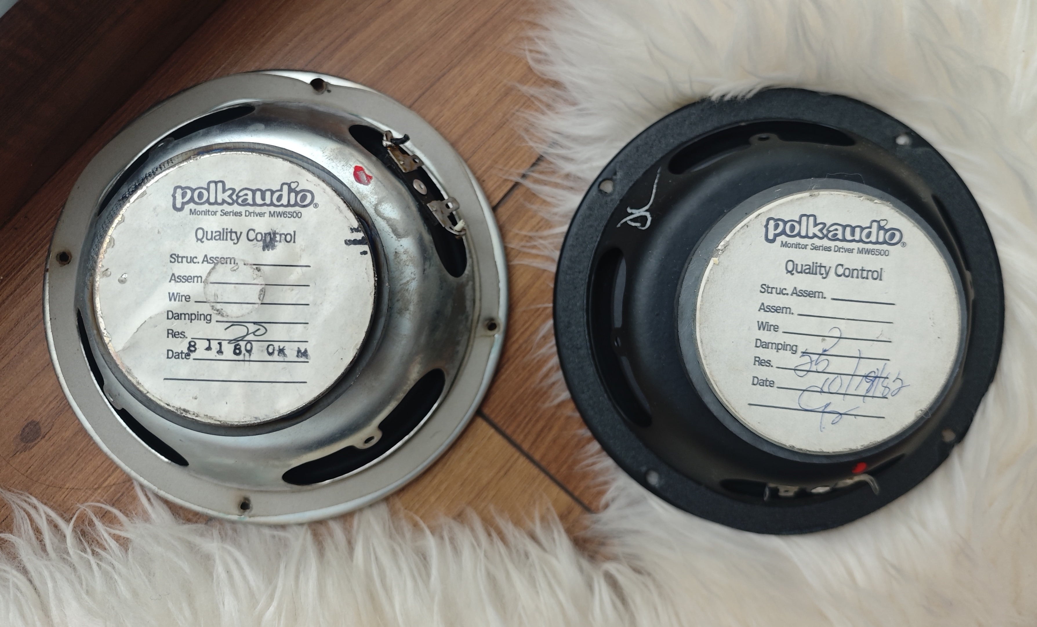
I recently purchased a pair of Monitor 5's and had originally intended on redoing the crossovers and gluing the speaker magnets. However, I noticed one of the drivers appears to have been replaced at some point, and the capacitance values on the crossover differs from the side I assume is all original (34uF on the replacement and 27uF on the original). The binding post also seems to be sourced from a monitor 7b instead. The sticker identifies both as MW6500 drivers, but I would like to ask if there would be any issues using them or if I would be better off sourcing a matching driver to replace it? Which capacitor values should I follow for the XO's?
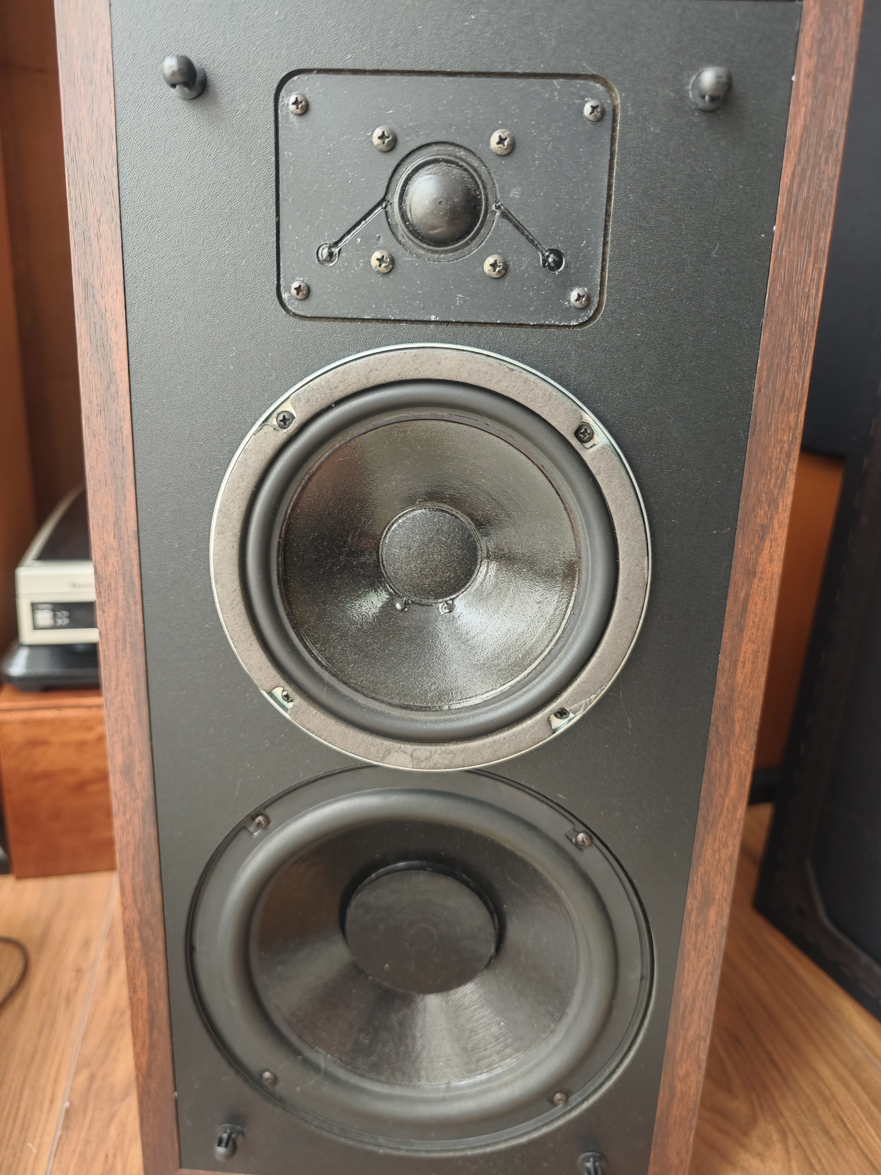
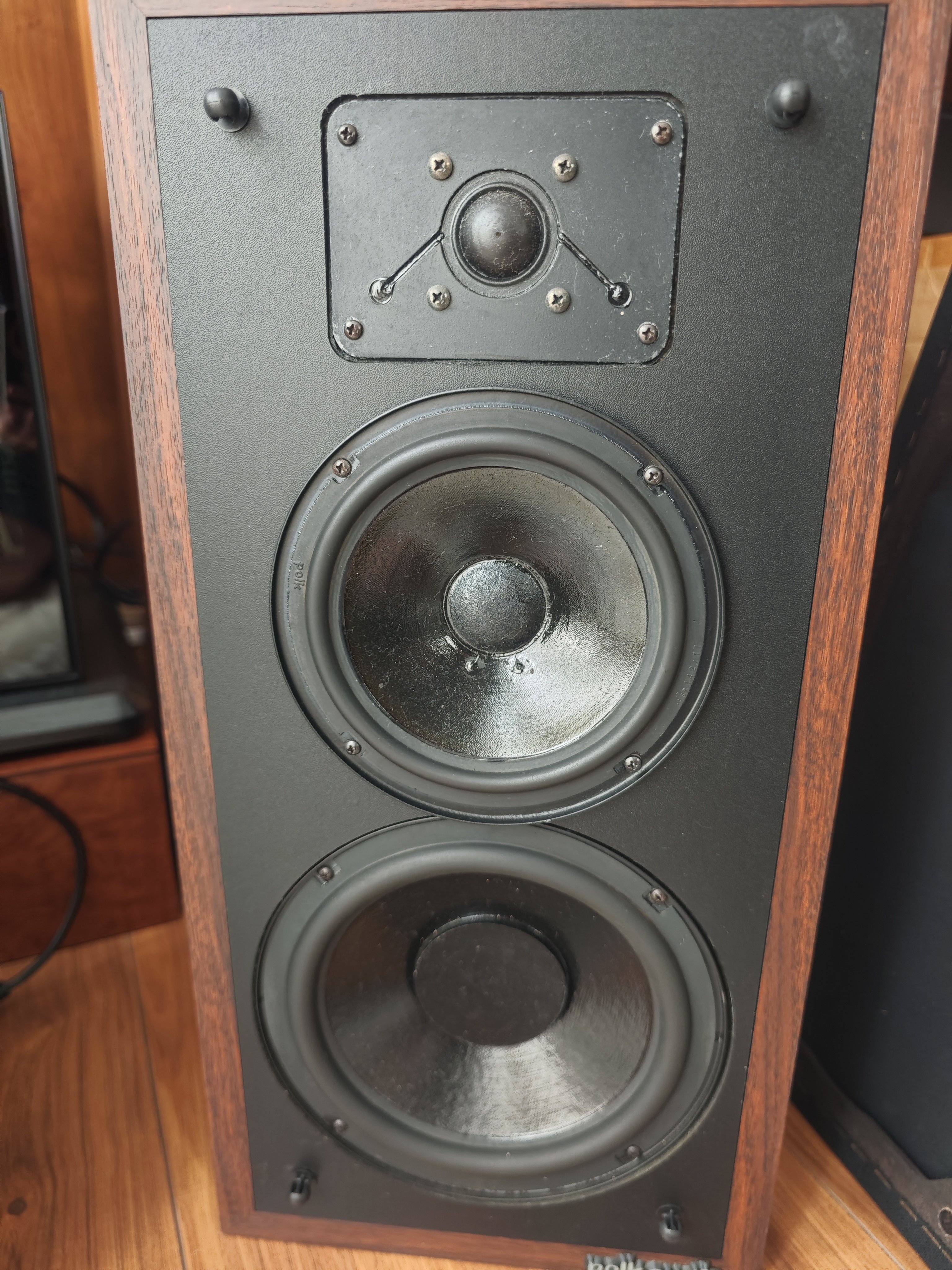
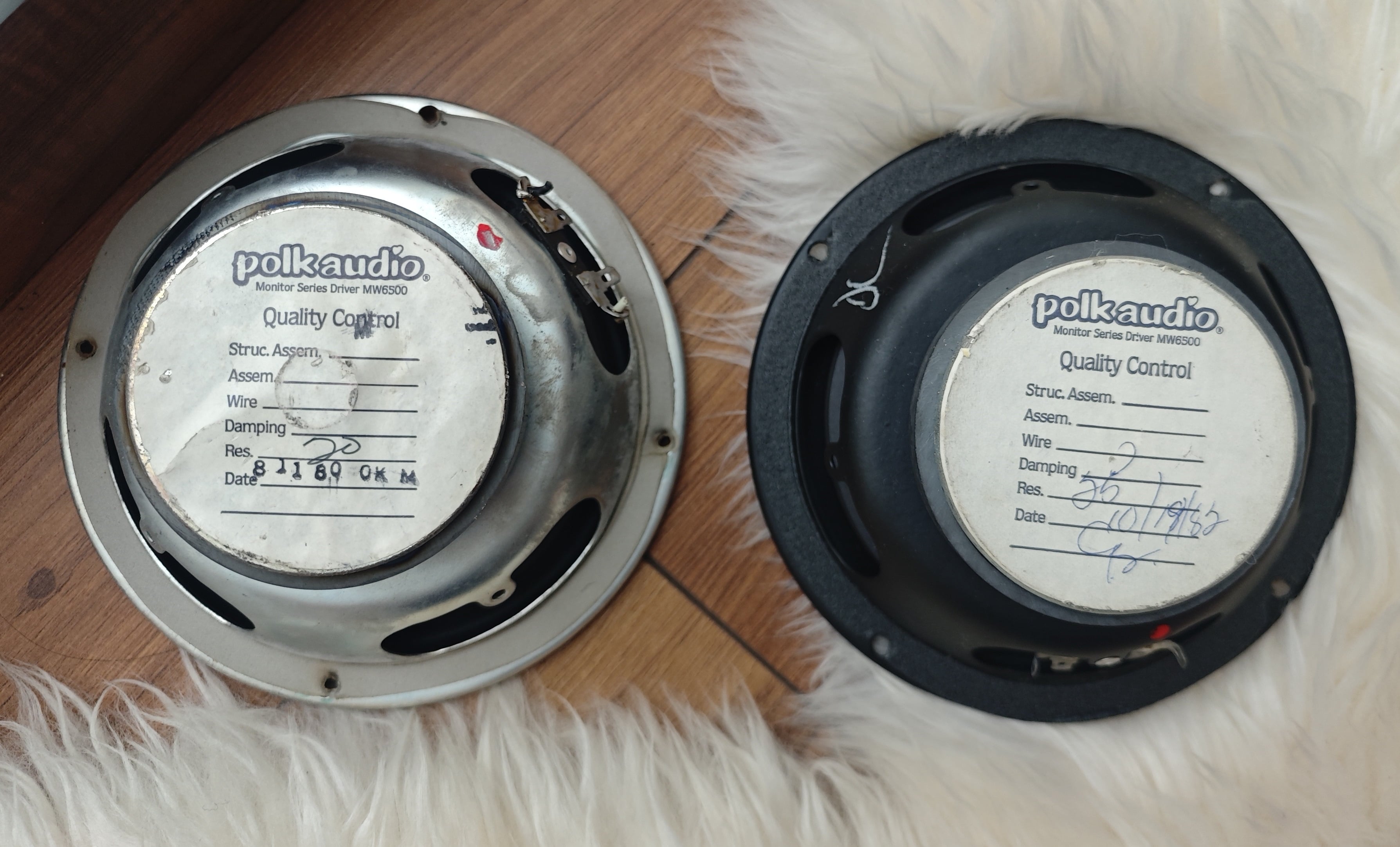
I recently purchased a pair of Monitor 5's and had originally intended on redoing the crossovers and gluing the speaker magnets. However, I noticed one of the drivers appears to have been replaced at some point, and the capacitance values on the crossover differs from the side I assume is all original (34uF on the replacement and 27uF on the original). The binding post also seems to be sourced from a monitor 7b instead. The sticker identifies both as MW6500 drivers, but I would like to ask if there would be any issues using them or if I would be better off sourcing a matching driver to replace it? Which capacitor values should I follow for the XO's?
Answers
-
My last few images didn't show for some reason.
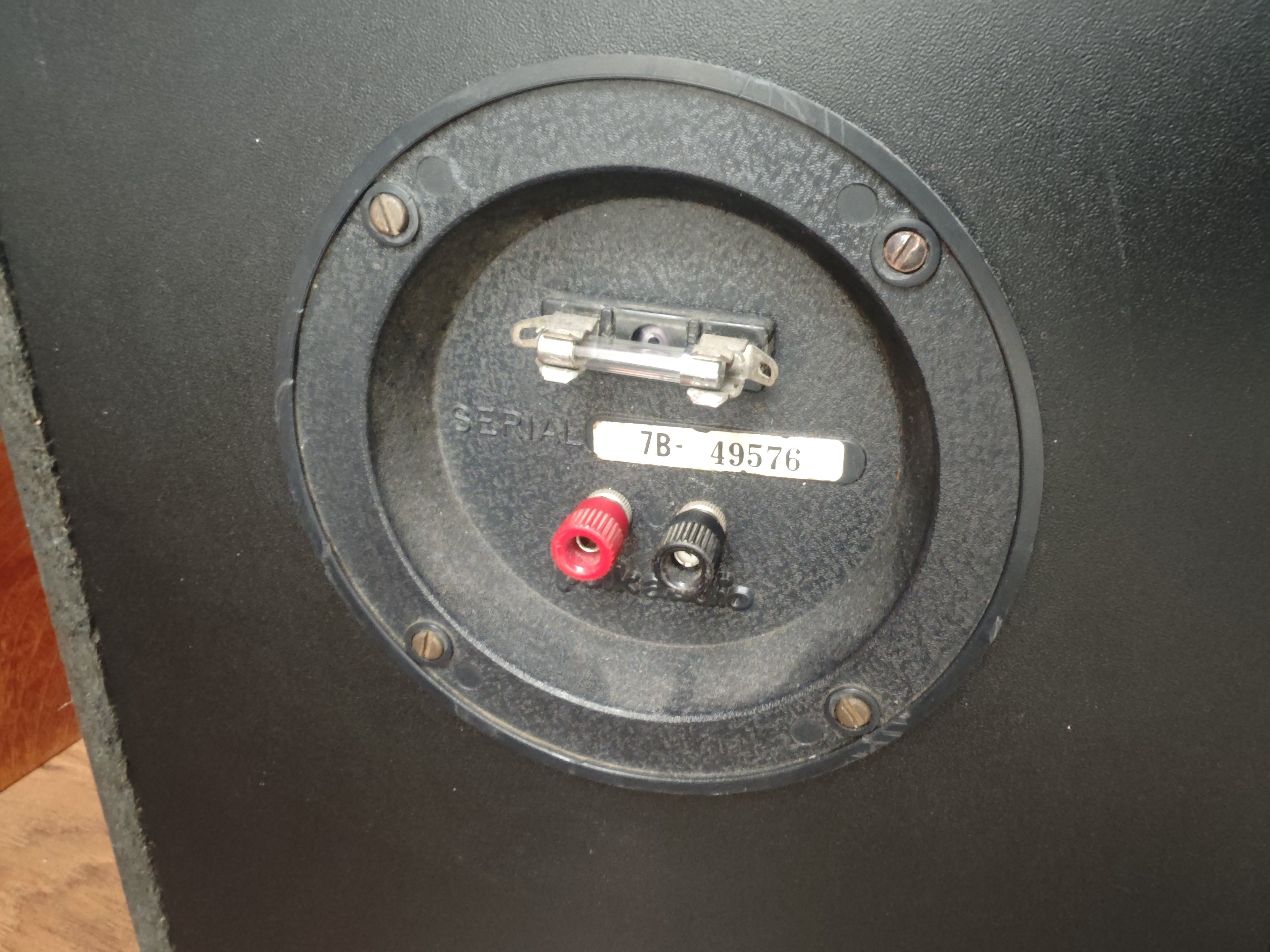
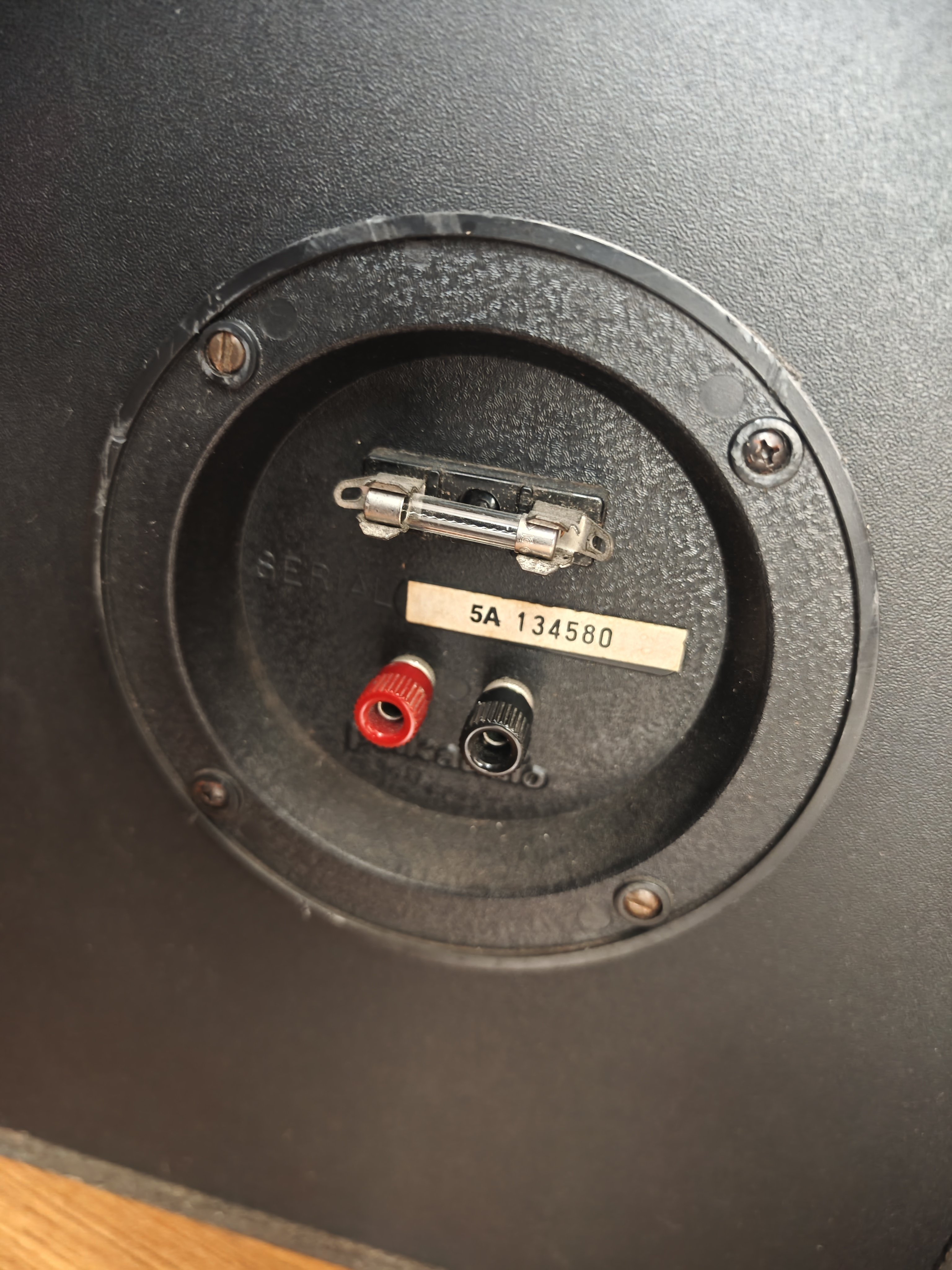
-
This content has been removed.
-
Thank you for your help so far. I was under the impression that both cabinets look to be a 5A model since they have peerless tweeters and lack the beveled front edge, is that not the case? And I assume there shouldn't be any audible differences between the two MW6500 drivers if I do a crossover upgrade with the same values for both?
-
Remove the paper ring off the silver driver, paint the silver basket face black and presto matching drivers.
Schematics are posted in the Crossover Schematics section.
The slotted screws on the binding post plates are not original. -
Wondering why one identifies as a 7B. Is it possible that someone swapped crossovers/binding posts? That could explain the different capacitance readings.
-
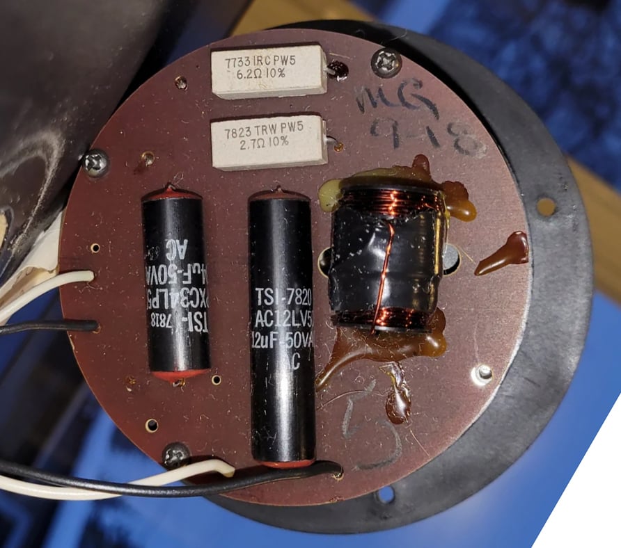
Capacitors should be 34uF and 12uF -
Those black and red Temple caps are HORRIBLE!
-
Wondering why one identifies as a 7B. Is it possible that someone swapped crossovers/binding posts? That could explain the different capacitance readings.
That was my thought as well. From what F1nut said about the slotted screws not being original, I'm guessing that the 5A speaker had work done on it as well since two of the screws were replaced.slow_polk7 wrote: »
Capacitors should be 34uF and 12uF
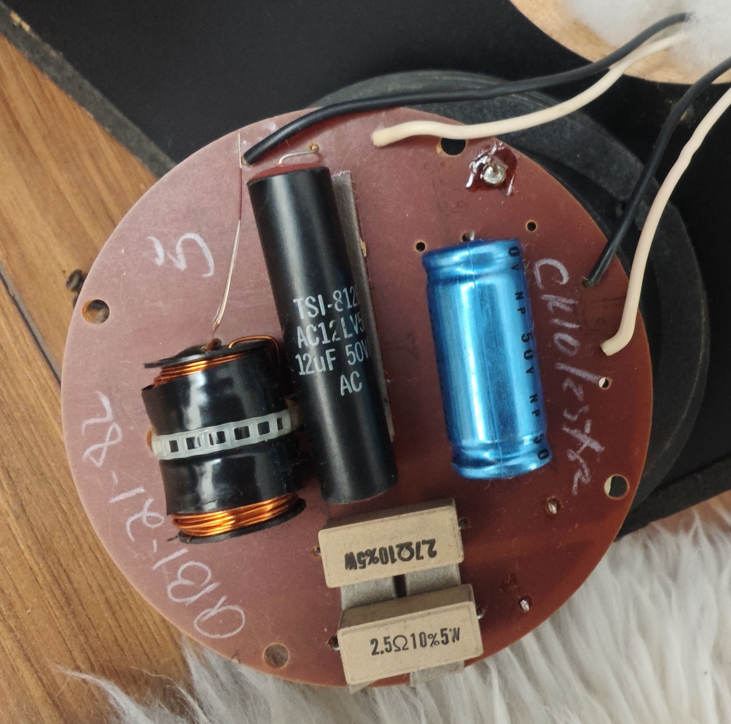
Strangely enough, both crossovers have different values for both the caps and resistors, and none of them match your example. Top one (from the 7B) has a mystery white cap and 34uF, bottom (from the 5A) has 12 and 27uF: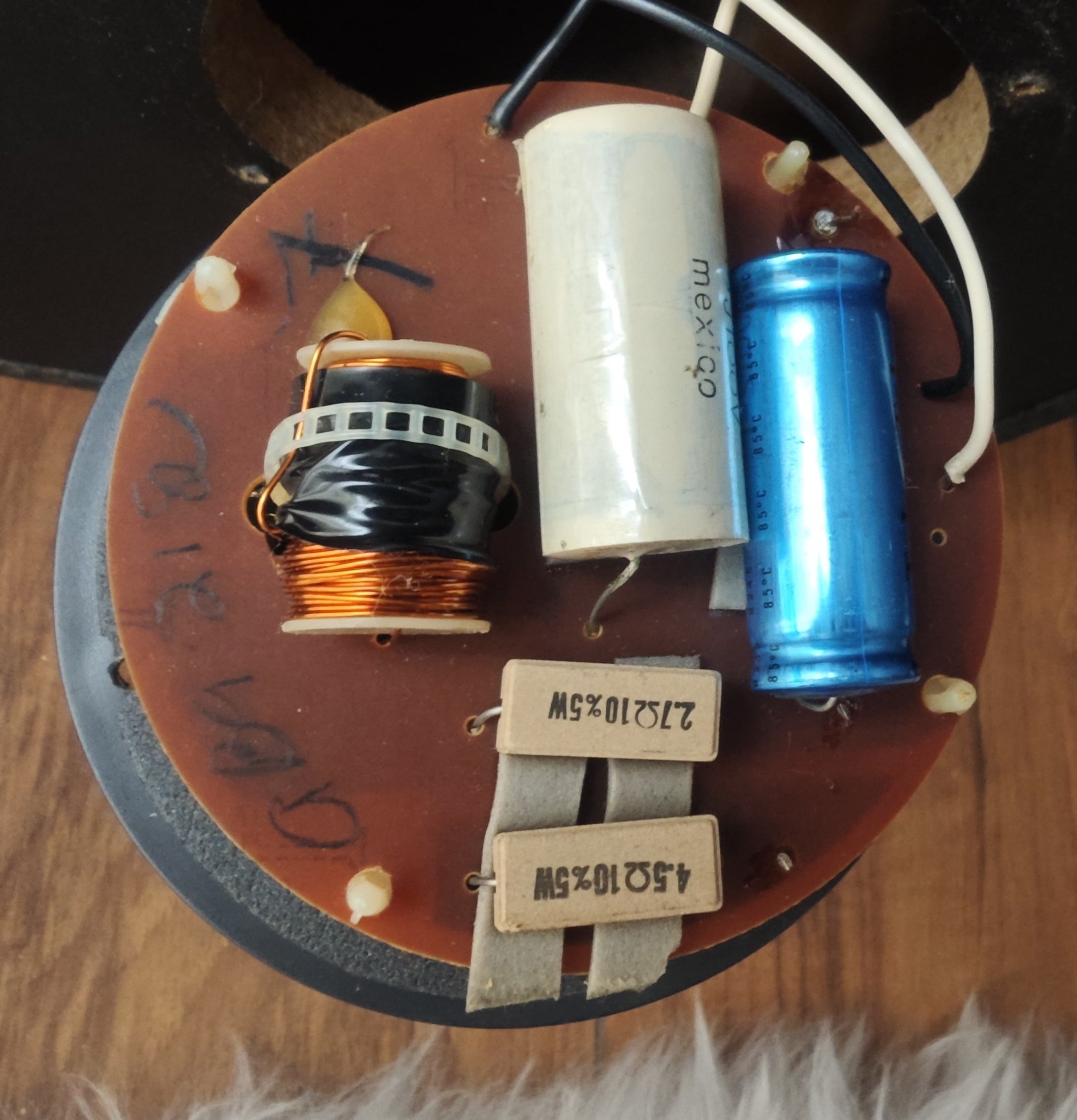
-
The values on the bottom crossover pic are correct for the 5A.
The mystery white cap is 12uF mylar. The inductor values are likely to be different between the 5A and 7B. Look for a 5A crossover on eBay.
Edit: here you go...
https://ebay.io/m/GaI8KS -
This content has been removed.
-
-
The values on the bottom crossover pic are correct for the 5A.
The mystery white cap is 12uF mylar. The inductor values are likely to be different between the 5A and 7B. Look for a 5A crossover on eBay.
Edit: here you go...
https://ebay.io/m/GaI8KS
Perfect, thank you for your help. Looking at the images the crossovers do have a big old "5" and a "7" on them, which makes a lot more sense in hindsight. Simplest explanation is someone probably swapped in the driver, crossover, and binding post from a 7 into the 5.
Purchased the replacement crossover you linked and shopping for replacement components for the recap right now. 👍
-
Get some Clarity CSA caps and Mills-Vishay resistors. You'll thank me later.
-
It would be interesting if you could measure the DC resistances of the inductors on the 5A board and compare to the values you get on the 7B one. Obviously they had to lower the series resistor for the tweeter, presumably because of the smaller baffle on the 5A.
Also - check the value of the fuse and make sure it is the proper 1A fast blow. That squiggly filament one is probably too high a value.George / NJ
Polk 7B main speakers, std. mods+ (1979, orig owner)
Martin Logan Dynamo sub w/6ft 14awg Power Cord
Onkyo A-8017 integrated
Logitech Squeezebox Touch Streamer w/EDO applet
iFi nano iDSD DAC
iPurifier3
iDefender w/ iPower PS
Custom Steve Wilson 1m UPOCC Interconnect
iFi Mercury 0.5m OFHC continuous cast copper USB cable
Custom Ribbon Speaker Cables, 5ft long, 4N Copper, 14awg, ultra low inductance
Custom Vibration Isolation Speaker Stands and Sub Platform -
I can check that, but is there a way to measure the inductor without desoldering it from the board? Otherwise I'll have to wait until the parts I ordered come in and do it when I do the crossover rebuild.
And thanks for the tip about the fuse, I did check based on your recommendation and it was indeed the wrong value. Replacement 1A fuses are on order as well.
-
I can check that, but is there a way to measure the inductor without desoldering it from the board? Otherwise I'll have to wait until the parts I ordered come in and do it when I do the crossover rebuild.
And thanks for the tip about the fuse, I did check based on your recommendation and it was indeed the wrong value. Replacement 1A fuses are on order as well.
Yeah you can check them easily without desoldering anything, as long as the tweeter isn't attached or the tweeter leads shorted to each other. Since we don't have the early schematics in the archives, and the early ones didn't give inductor DCR / awg specs, you would be doing a good service.George / NJ
Polk 7B main speakers, std. mods+ (1979, orig owner)
Martin Logan Dynamo sub w/6ft 14awg Power Cord
Onkyo A-8017 integrated
Logitech Squeezebox Touch Streamer w/EDO applet
iFi nano iDSD DAC
iPurifier3
iDefender w/ iPower PS
Custom Steve Wilson 1m UPOCC Interconnect
iFi Mercury 0.5m OFHC continuous cast copper USB cable
Custom Ribbon Speaker Cables, 5ft long, 4N Copper, 14awg, ultra low inductance
Custom Vibration Isolation Speaker Stands and Sub Platform -
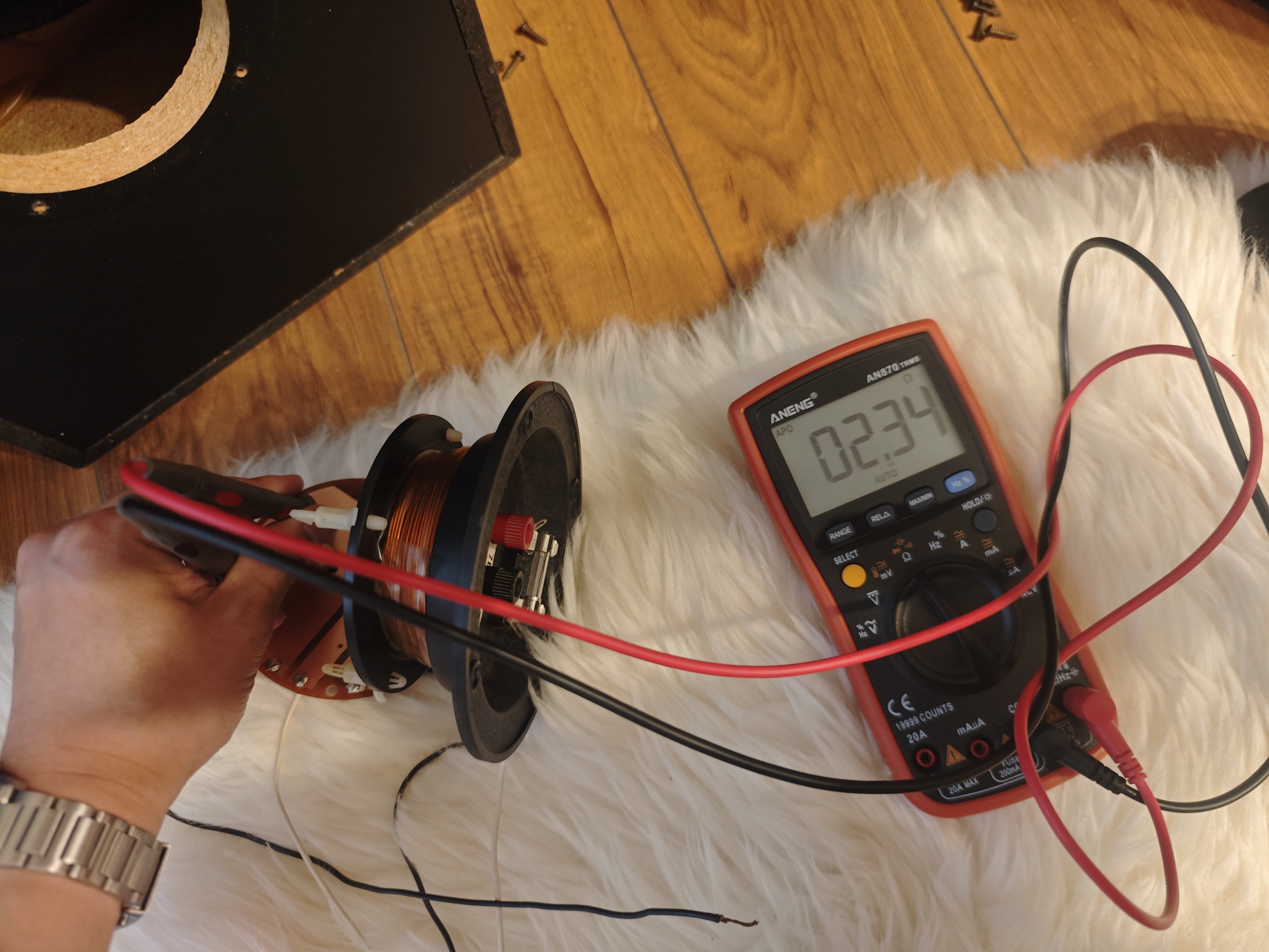
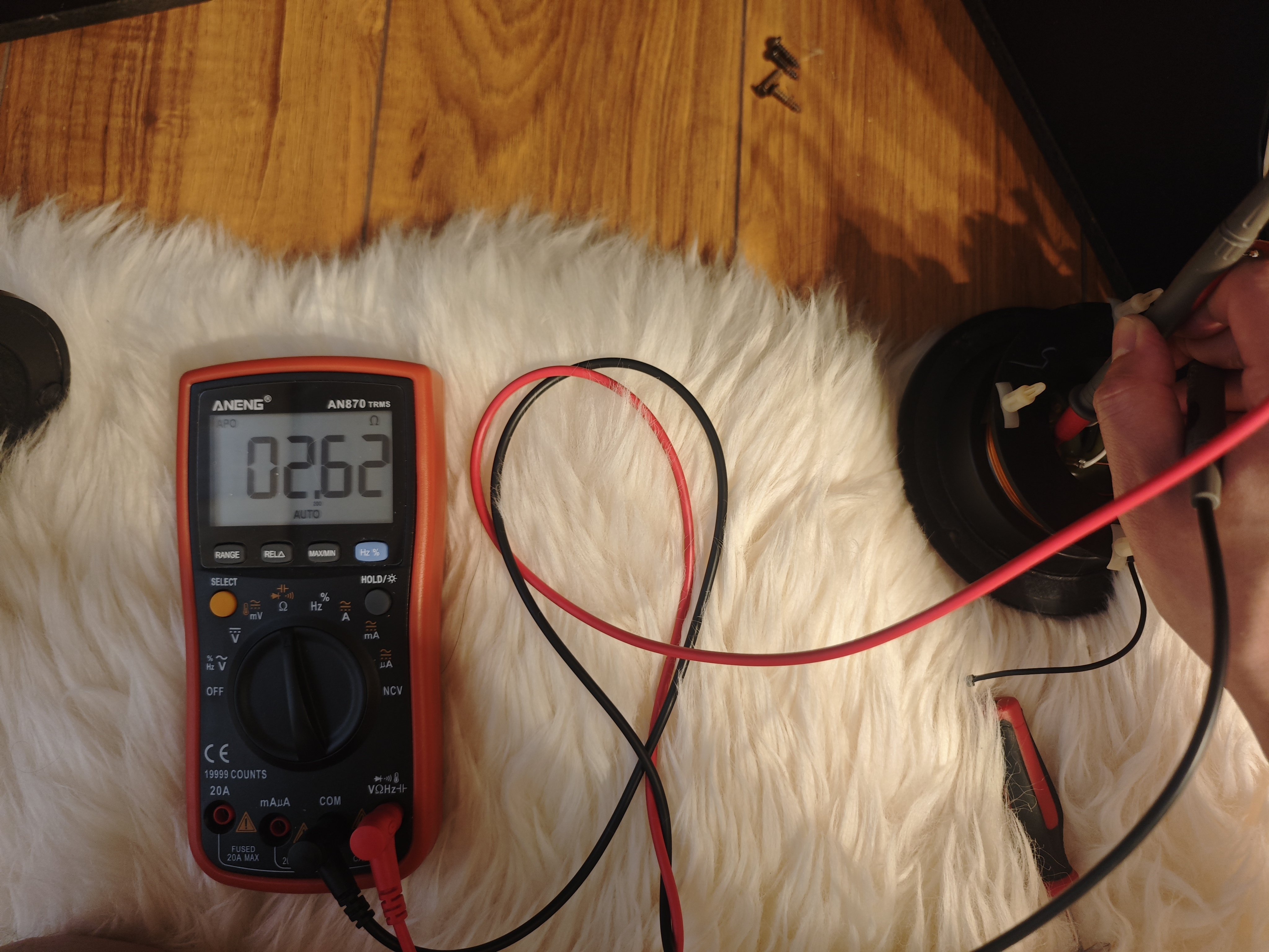
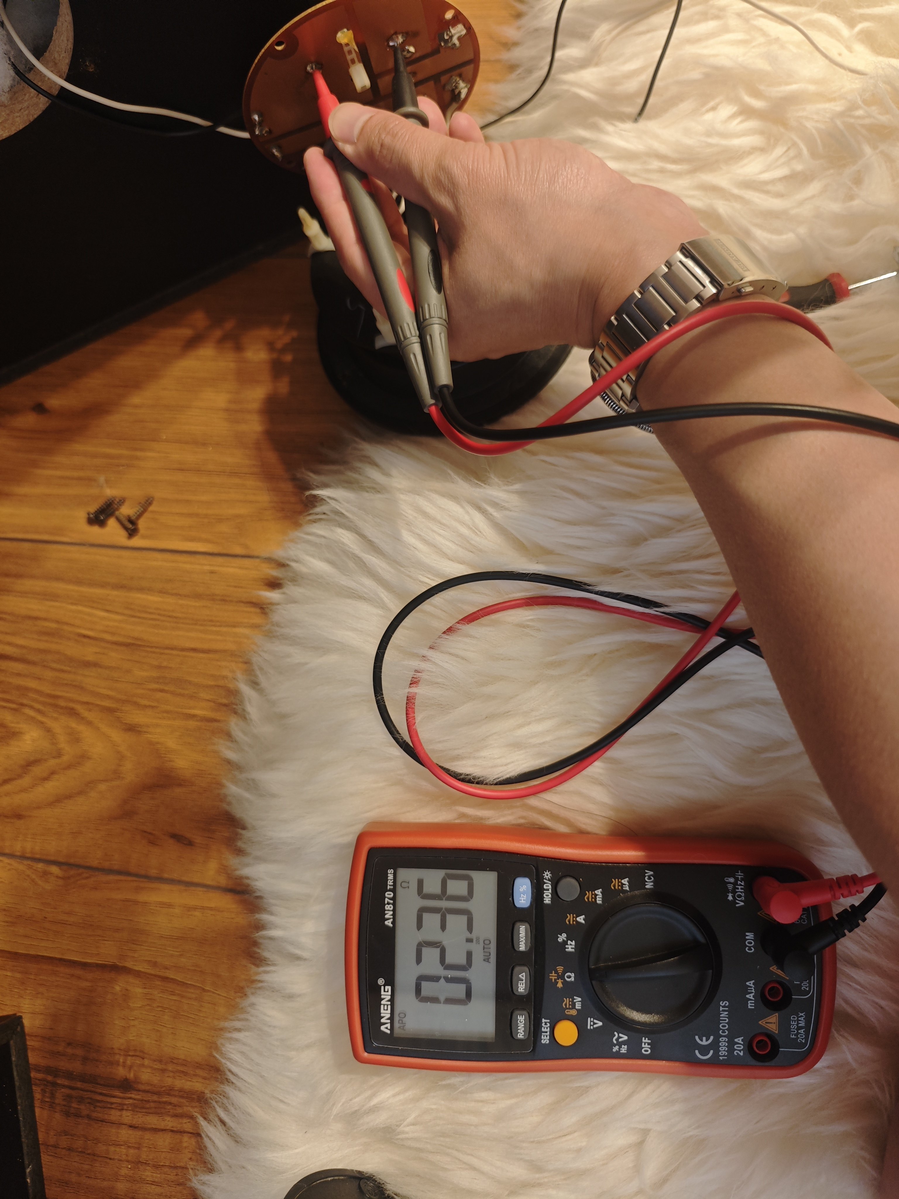
Here are the DC resistance values I was able to measure from the crossovers. All measurements were taken with the woofer and tweeter removed and directly across the inductor leads:
- Monitor 7 large inductor (at base of terminal plate): 2.50Ω
- Monitor 7 small (on XO board): 2.34Ω
- Monitor 5 large inductor: 2.62Ω
- Monitor 5 small inductor: 2.36Ω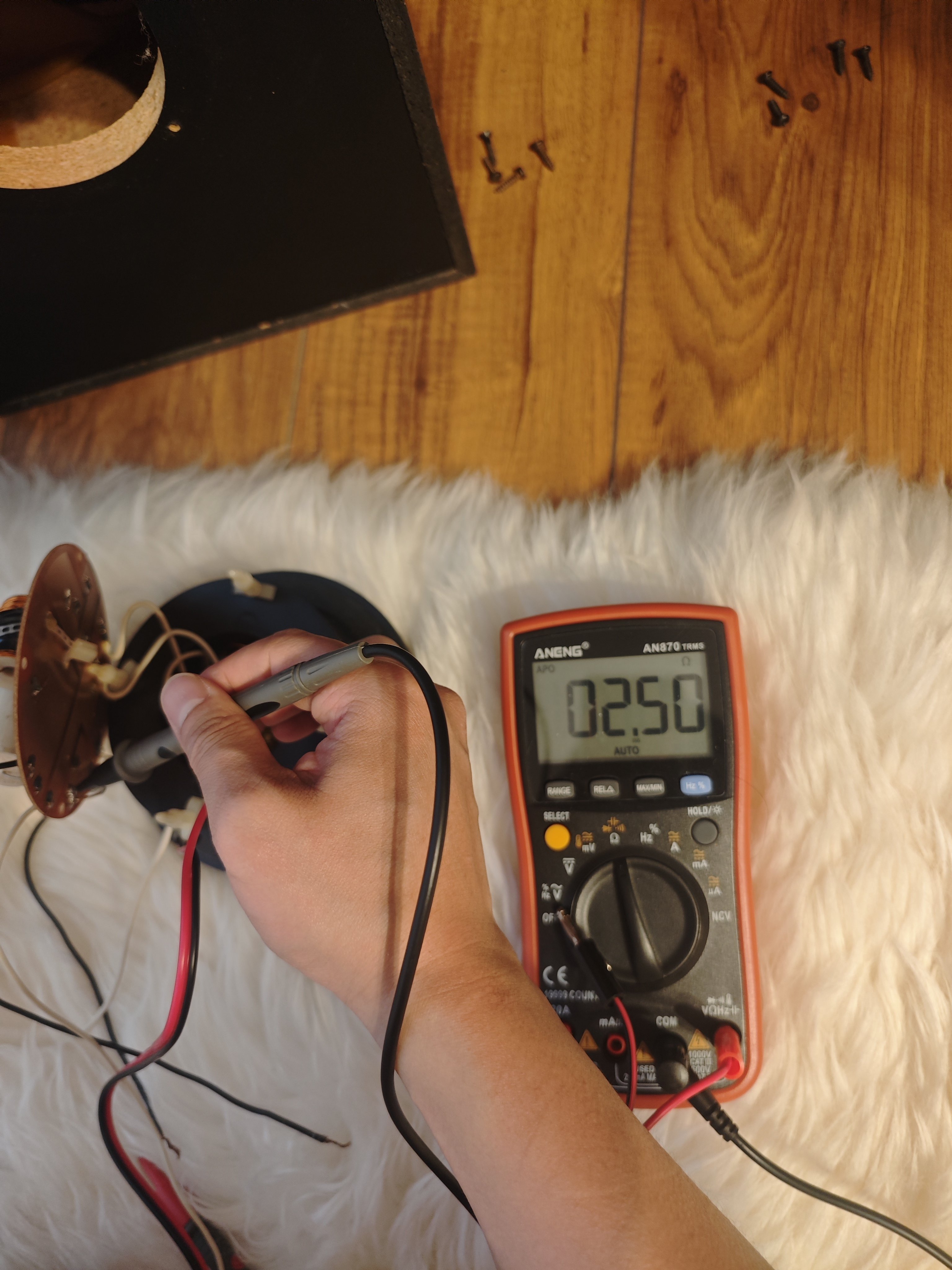
-
Important thing is you got basically the same readings so most likely the inductances are the same as well, between 5A and 7B crossovers. Hard to read low resistances without a good meter. When the battery wasn't dead on mine I got around 0.7 Ohms for both on the M7 crossover.George / NJ
Polk 7B main speakers, std. mods+ (1979, orig owner)
Martin Logan Dynamo sub w/6ft 14awg Power Cord
Onkyo A-8017 integrated
Logitech Squeezebox Touch Streamer w/EDO applet
iFi nano iDSD DAC
iPurifier3
iDefender w/ iPower PS
Custom Steve Wilson 1m UPOCC Interconnect
iFi Mercury 0.5m OFHC continuous cast copper USB cable
Custom Ribbon Speaker Cables, 5ft long, 4N Copper, 14awg, ultra low inductance
Custom Vibration Isolation Speaker Stands and Sub Platform