Monitor 4 Crossover Question
Options

kevinko
Posts: 165
A fellow forum member is upgrading the crossovers from my original 4s w/Peerless. I shipped them to him and here is what he found:
"Your crossovers are NOT the published Monitor 4 circuit. Nor are they anything I've ever seen in a Polk.
From first appearances, I thought they used a Monitor 5 Jr circuit, but it's not even close to that. The good news is there is only 1 cap to replace. The bad news is I don't have it.
It is in parallel to the tweeter, so it is not as critical as one in series. 5.8uF is a somewhat unusual value. Most manufacturers seem to offer a 5.6uF, to which I could add a byass for the extra 0.2uF."
Attached at the very bottom is the schematic I received from Polk CS.
Apparently there is a discrepancy:
"...the cap is clearly in parallel with the tweeter, not the mid"

JS's drawing of my crossover:

Any opinions on my options here?
I was originally going to have him install Claritys but other recommendations are welcome.
"Your crossovers are NOT the published Monitor 4 circuit. Nor are they anything I've ever seen in a Polk.
From first appearances, I thought they used a Monitor 5 Jr circuit, but it's not even close to that. The good news is there is only 1 cap to replace. The bad news is I don't have it.
It is in parallel to the tweeter, so it is not as critical as one in series. 5.8uF is a somewhat unusual value. Most manufacturers seem to offer a 5.6uF, to which I could add a byass for the extra 0.2uF."
Attached at the very bottom is the schematic I received from Polk CS.
Apparently there is a discrepancy:
"...the cap is clearly in parallel with the tweeter, not the mid"
JS's drawing of my crossover:
Any opinions on my options here?
I was originally going to have him install Claritys but other recommendations are welcome.
Comments
-
The schematic Polk gave you is for the version using the SL1000 tweeter.
Post a picture of your speaker and its crossover.
I don't know who JS is, but he is correct that the .02uF will act as a bypass cap, which you do not want. I'm surprised this person doesn't know that Sonicap has a 5.8uF.Political Correctness'.........defined
"A doctrine fostered by a delusional, illogical minority and rabidly promoted by an unscrupulous mainstream media, which holds forth the proposition that it is entirely possible to pick up a t-u-r-d by the clean end."
President of Club Polk -
Polk's schematic says "HF1000"... And I don't believe they made a Monitor 4 with the SL1000. So something is amiss.
Anyway, thanks for the info about the Sonicaps.
Cute little things ain't they?

-
They kind of fell into my lap. I did a nation-wide Craigslist search for Monitor 4s and found a seller in Pennsylvania who was willing to ship them to Wisconsin.
-
HF stands for high frequency and 1000 means SL1000.
Anyway, best to replace the components as found.Political Correctness'.........defined
"A doctrine fostered by a delusional, illogical minority and rabidly promoted by an unscrupulous mainstream media, which holds forth the proposition that it is entirely possible to pick up a t-u-r-d by the clean end."
President of Club Polk -
Something is very wrong. In a simple 1st order High Pass circuit, there's a Capacitor in Series with the Tweeter. An additional shunt inductor down stream, parallel with the Tweeter will create a 2nd order High Pass circuit. A cap in parallel with the Tweeter will not filter low frequencies.
In a the Low Pass, the components are reversed. The Inductor is in Series with the woofer, and the Capacitor, if equipped in in parallel, downstream.Home Theater/2 Channel:
Front: SDA-2ATL forum.polkaudio.com/discussion/143984/my-2as-finally-finished-almost/p1
Center: Custom Built forum.polkaudio.com/discussion/150760/my-center-channel-project/p1
Surrounds & Rears: Custom Built forum.polkaudio.com/discussion/151647/my-surround-project/p1
Sonicaps, Mills, RDO-194s-198s, Dynamat, Hurricane Nuts, Blackhole5
Pioneer Elite VSX-72TXV, Carver PM-600, SVS PB2-Plus Subwoofer
dhsspeakerservice.com/ -
westmassguy wrote: »Something is very wrong. In a simple 1st order High Pass circuit, there's a Capacitor in Series with the Tweeter. An additional shunt inductor down stream, parallel with the Tweeter will create a 2nd order High Pass circuit. A cap in parallel with the Tweeter will not filter low frequencies.
In a the Low Pass, the components are reversed. The Inductor is in Series with the woofer, and the Capacitor, if equipped in in parallel, downstream.
I was thinking the same thing. That circuit should not work. I think someone messed with the crossover.
Also, how does the small wire disconnect shown work with a Peerless? The ones I have seen have 2 medium sized disconnects (the same size as the driver tabs). I thought only the later model tweeters has different sized tabs -
The Peerless from that era were normally soldered. If they weren't, then that quick connect appears to be the correct .125"Home Theater/2 Channel:
Front: SDA-2ATL forum.polkaudio.com/discussion/143984/my-2as-finally-finished-almost/p1
Center: Custom Built forum.polkaudio.com/discussion/150760/my-center-channel-project/p1
Surrounds & Rears: Custom Built forum.polkaudio.com/discussion/151647/my-surround-project/p1
Sonicaps, Mills, RDO-194s-198s, Dynamat, Hurricane Nuts, Blackhole5
Pioneer Elite VSX-72TXV, Carver PM-600, SVS PB2-Plus Subwoofer
dhsspeakerservice.com/ -
HF stands for high frequency and 1000 means SL1000.
Anyway, best to replace the components as found.
I thought that HF1000 was Polk's designation for the Peerless. ? -
News to me.
The date on that schematic is way past the time Polk was using the Peerless.Political Correctness'.........defined
"A doctrine fostered by a delusional, illogical minority and rabidly promoted by an unscrupulous mainstream media, which holds forth the proposition that it is entirely possible to pick up a t-u-r-d by the clean end."
President of Club Polk -
Another 4 crossover from a previous thread:

http://forum.polkaudio.com/discussion/174722/monitor-4-with-peerless-too-bright
Mine again for comparison:
-
Any opinions on this new re-configuration?

The old again for comparison:
-
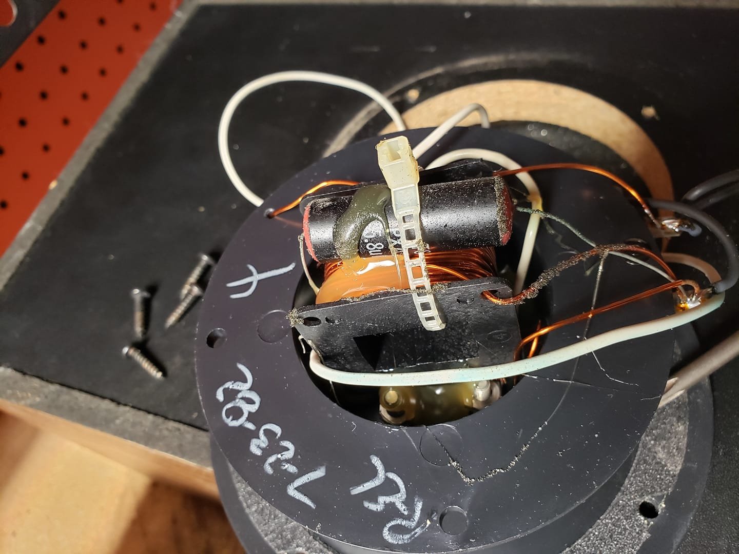
Happy to find this old thread. I just bought a pair of Polk Monitor 4 speakers with the peerless tweeters, MW6500 drivers, rosewood vinyl, a fuse holder and the same crossover's you have discussed in this thread. The crossovers have a hand written date of August of 1982. I also purchased a donor cabinet with no drivers but it did include the crossover and grill cover. This crossover has a printed sticker and is dated December 1983. It also matches the crossovers of the pair I purchased as well as the crossovers discussed in this thread. Crossover pictures are attached. So my question, just replace the capacitor and run them or should I reconfigure the crossover to address the observations of Westmassguy and the fact the capacitor is in parallel?


-
Just replace the capacitor. On a second second look at a 2 1/2 year old post I don't think the cap in either crossover pic is in parallel. Your pics show one lead of the capacitor going to the tab that then goes to your tweeter positive (correct?). Where does the other cap lead go? If it goes to one side of the fuseholder (that is connected to the positive speaker post) the capacitor is in series.
Even if it is hard to see where every wire goes just trust that Polk put it together right. Sure there are a few documented errors in assembly that come up occasionally. But I don't think they screwed up every time they made one of their simplest crossovers. Just snip the leans and solder in a decent film cap. Easiest "rebuild" you could ever dream of.
-

I have some Monitor 4's from 1982 that no longer have great sound (one's real bassy, the other trebely). The cones look good and move easily so I think it must be the COs. The COs are the fused type that were used on Monitor 5B's, and they look completely different that what I see here. In addition, they are a little different than the the posted schematics for 5B's. Image attached. Should I just get 5B COs from ebay and go for it?
Post edited by robertjgeoghegan on -
Monitor 4 crossovers appear to be all over the place.afterburnt wrote: »They didn't speak a word of English, they were from South Carolina.
Village Idiot of Club Polk -
I cannot make out the values of all of the caps, but I had a pair of early 4's that had crossovers that were identical to a Monitor 10 crossover. Did not make sense, but they were original and I rebuilt them with the same values that were on the board.
-
Faustin: Now that I have seen the Monitor 10 diagrams by dorokusai, my M4 CO is the same (caps are 12, 12, 34uF), except I don't know the values of the induction coils on mine. (My sketch above has an error in it.) Do you have a good source for the caps and resistors for replacement? (I would assume the coils are bullet-proof and can stay.)
-
-
^^^^^^^ - Sonicraft if you want higher end components. Parts Express for less expensive Dayton caps.
-
I have a set of the early 4's with the 3 component crossover.
That 5.8 cap is indeed in parallel. One lead to the tweet ,the other goes to the negative binding post. The tweet coil is in series,one leg to the positive binding post, the other to the tweet positive along the capacitor.
The low pass coil is in series with the woofer with one lead going to the pos. input post...also attached there is the feed to one side of the fuse...other side is white wire to the tweet neg lug. These appeared to be all original, but in my OCD I rewired them by removing the fuse from the circuit, placing the cap in series and the coil parallel downstream.
I wonder if these early units were miswired...such that the coil and the cap were swapped at the binding posts.LS90's...Monitor 10a's....7's....and now 4'shttp://www.polkaudio.com/forums/images/smilies/037/icon_mrgreen.gif -
On further research it would appear that these very early monitor 4 crossovers are series type and not the more common parallel type.
Perhaps it was to save some cost by reducing component counts, perhaps the designers thought it offered better performance,ect.
Regardless I believe these are the only monitors to use this type of crossover, all subsequent monitor models use the more conventional parallel typeLS90's...Monitor 10a's....7's....and now 4'shttp://www.polkaudio.com/forums/images/smilies/037/icon_mrgreen.gif -
Thank you for your comments. I did see all the referred info while searching earlier. Looks like my original xovr (3 capacitors, 2 12uF, 1 34uF) were the very early versions, superseded by the ones I bought. I don't see much sense in replacing the capacitors (and fixing any other issues) and reinstalling these early xovrs, the newer versions I bought seem to work fine, although I don't understand the "parallel" circuit compared to a more normal "series" capacitor to the tweeter.
-
I don't know. My sense is that it couldn't possibly be that the inductor is in series and the capacitor in parallel, with the tweeter. That would be a low pass second order circuit which makes no sense to me. The MW having the inductor in series makes sense because that is a first order low pass circuit.
This is a missing link crossover. At some point Polk went from an 8 ohm nom. Peerless/ 8 ohm nom. impedance MW6500 to the SL1500 (I think) combined with the 4 ohm nom. impedance MW6502. There is such a thing as a 4 ohm nom. impedance Peerless but to my knowledge Polk never used it for whatever reasons but could they possibly have tried it with the MW6502 in this missing link crossover?George / NJ
Polk 7B main speakers, std. mods+ (1979, orig owner)
Martin Logan Dynamo sub w/6ft 14awg Power Cord
Onkyo A-8017 integrated
Logitech Squeezebox Touch Streamer w/EDO applet
iFi nano iDSD DAC
iPurifier3
iDefender w/ iPower PS
Custom Steve Wilson 1m UPOCC Interconnect
iFi Mercury 0.5m OFHC continuous cast copper USB cable
Custom Ribbon Speaker Cables, 5ft long, 4N Copper, 14awg, ultra low inductance
Custom Vibration Isolation Speaker Stands and Sub Platform -
My M4s w/ peerless tweeter and July 1982 XO.
-
Is the 5.8uf cap in series with the tweeter and the small inductor is in parallel?
Do you have a 8 ohm Peerless with the MW6500?George / NJ
Polk 7B main speakers, std. mods+ (1979, orig owner)
Martin Logan Dynamo sub w/6ft 14awg Power Cord
Onkyo A-8017 integrated
Logitech Squeezebox Touch Streamer w/EDO applet
iFi nano iDSD DAC
iPurifier3
iDefender w/ iPower PS
Custom Steve Wilson 1m UPOCC Interconnect
iFi Mercury 0.5m OFHC continuous cast copper USB cable
Custom Ribbon Speaker Cables, 5ft long, 4N Copper, 14awg, ultra low inductance
Custom Vibration Isolation Speaker Stands and Sub Platform -
Just to correct something I wrote above......the 4 ohm tweeter after the Peerless (paired with the MW6500 in 1982 and 1983) that they first paired up with the MW6502 in the 4A in 1984, I do not know the model# of (HF1000?) but it was not the SL1500. The SL1500 was the tweeter they put in the 4 SeriesII in 1990 (maybe 1989?).George / NJ
Polk 7B main speakers, std. mods+ (1979, orig owner)
Martin Logan Dynamo sub w/6ft 14awg Power Cord
Onkyo A-8017 integrated
Logitech Squeezebox Touch Streamer w/EDO applet
iFi nano iDSD DAC
iPurifier3
iDefender w/ iPower PS
Custom Steve Wilson 1m UPOCC Interconnect
iFi Mercury 0.5m OFHC continuous cast copper USB cable
Custom Ribbon Speaker Cables, 5ft long, 4N Copper, 14awg, ultra low inductance
Custom Vibration Isolation Speaker Stands and Sub Platform -
HF1000 in 99.9% was the SL1000 tweeter.
-
HF1000 in 99.9% was the SL1000 tweeter.
I don't believe so. The SL1000 wasn't a 4 ohm tweeter, it was something Polk came up to serve as a stop gap measure when the Peerless went out of production. I saw a buyer's guide full page ad from 1984 where Polk said the SL1000 was in all of the speakers except the 4A, which they didn't specify any model# for.
Here's what I think Polk was referring to as the HF1000. I have to say that they did refer to the Peerless sometimes as the HF1000 in the RTA11/Model 11 manual however, but maybe they were fast and loose with the ol' HF1000 designation: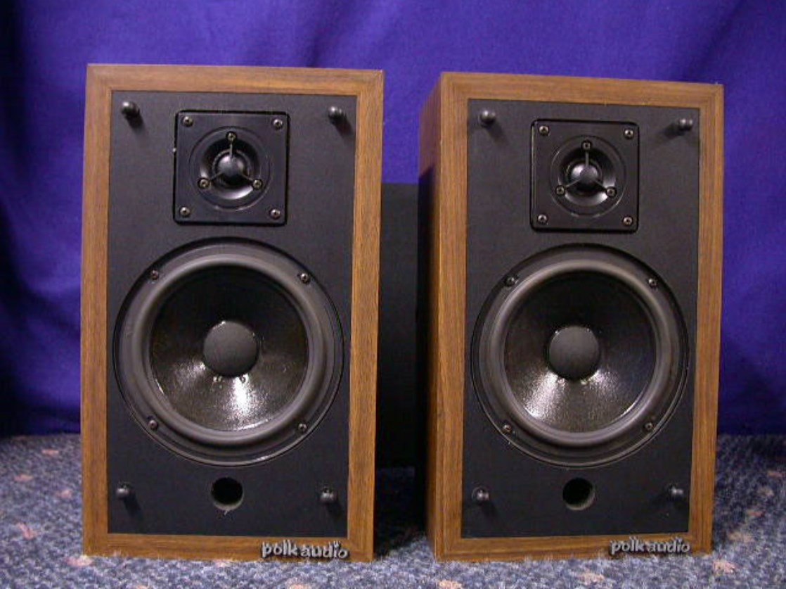
this is from Audio Oct. 1984
George / NJ
Polk 7B main speakers, std. mods+ (1979, orig owner)
Martin Logan Dynamo sub w/6ft 14awg Power Cord
Onkyo A-8017 integrated
Logitech Squeezebox Touch Streamer w/EDO applet
iFi nano iDSD DAC
iPurifier3
iDefender w/ iPower PS
Custom Steve Wilson 1m UPOCC Interconnect
iFi Mercury 0.5m OFHC continuous cast copper USB cable
Custom Ribbon Speaker Cables, 5ft long, 4N Copper, 14awg, ultra low inductance
Custom Vibration Isolation Speaker Stands and Sub Platform -
@dorokusai
Maybe this semi mysterious unofficial redraw of a missing(?) original schematic should be put into the archives. I think the date is 2/27/89? Couldn't be 1984 as I initially though it was. The MW6500 was not being used in the M4 from 1984 on when they were using the MW6502 and they went to M4A. Also, the Metro Drive location wasn't pre 1986.
So maybe HF1000 was indeed the Peerless.
@volcano Make sure you have your Peerless tweeter connected in reverse polarity as per the schematic. Probably necessary to avoid a summation hump at the crossover freq.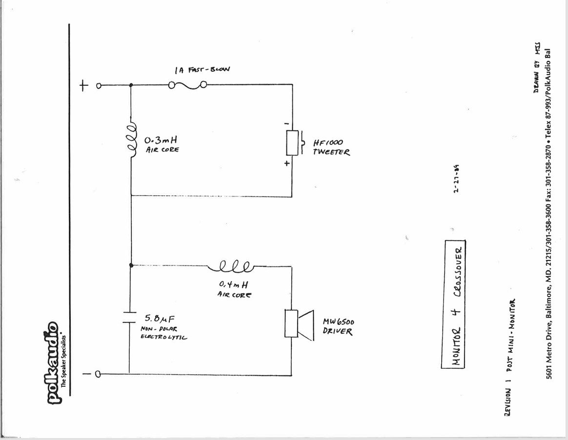
George / NJ
Polk 7B main speakers, std. mods+ (1979, orig owner)
Martin Logan Dynamo sub w/6ft 14awg Power Cord
Onkyo A-8017 integrated
Logitech Squeezebox Touch Streamer w/EDO applet
iFi nano iDSD DAC
iPurifier3
iDefender w/ iPower PS
Custom Steve Wilson 1m UPOCC Interconnect
iFi Mercury 0.5m OFHC continuous cast copper USB cable
Custom Ribbon Speaker Cables, 5ft long, 4N Copper, 14awg, ultra low inductance
Custom Vibration Isolation Speaker Stands and Sub Platform -
Your best bet would be Ken @SeleniumFalcon. Mark @dorokusai has been gone from Polk for many years.


