CS1000P Resister Value?
codymaxfield
Posts: 13
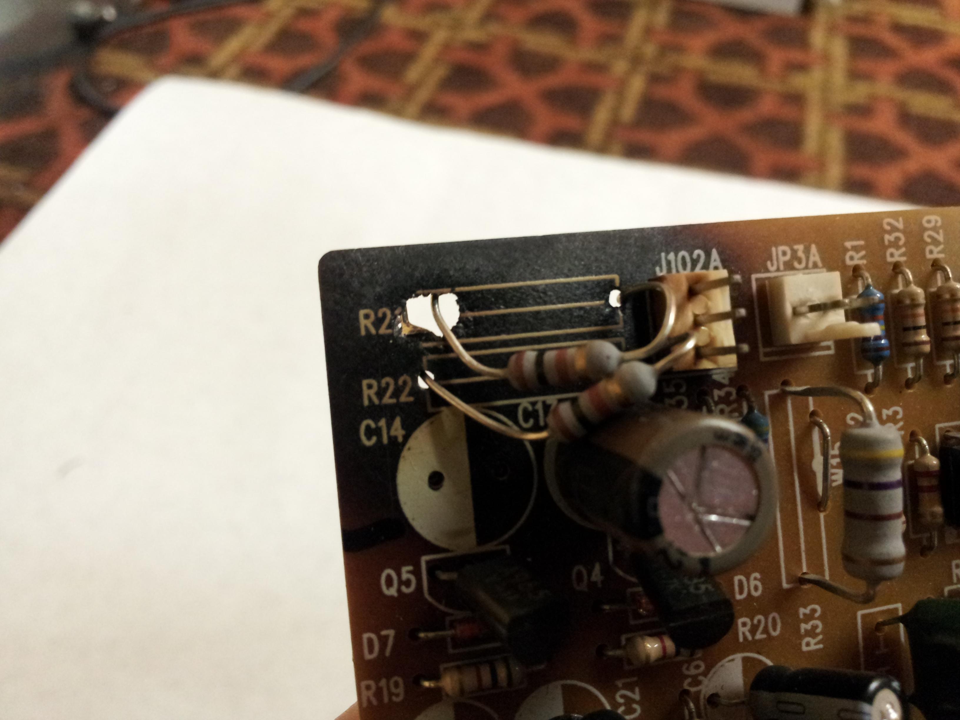
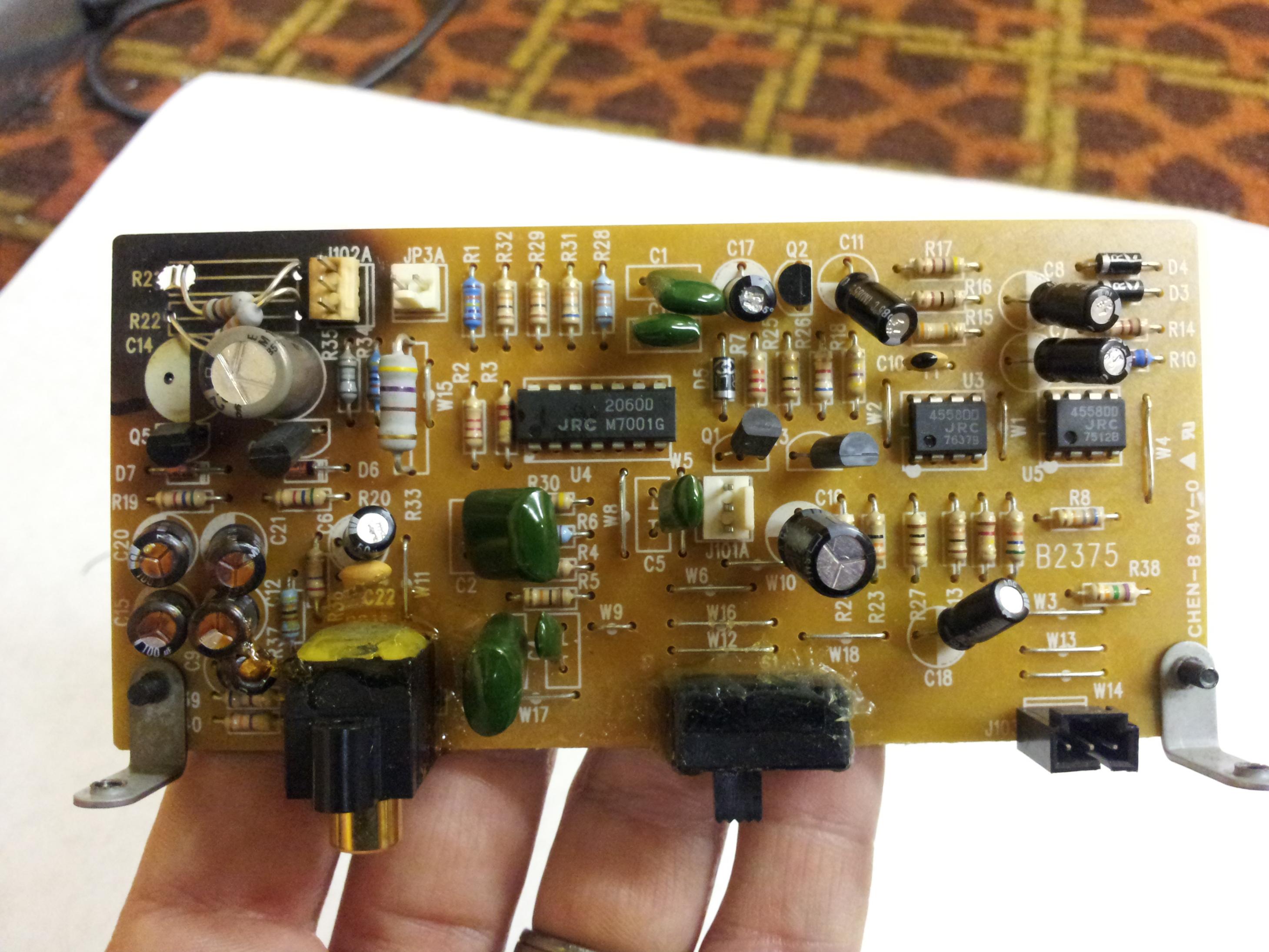
I have a CS1000P that had a couple of resisters burn up, and I need to know the value of them so I can repair it. The board is B2375 and it is resister R22 and R23. I got a schematic from Helen Yarbor at Polk, but it is too blurry to read any of the numbers. If anyone can help I would really appreciate it. The resisters in the pics are not the right value.
Sincerely,
Cody

Sincerely,
Cody


Post edited by codymaxfield on
Comments
-
I take it you're not a service tech since you can't spell resistor. I'd suggest you send the board to Polk for repair.Political Correctness'.........defined
"A doctrine fostered by a delusional, illogical minority and rabidly promoted by an unscrupulous mainstream media, which holds forth the proposition that it is entirely possible to pick up a t-u-r-d by the clean end."
President of Club Polk -
Sorry I guess I have become lazy and assumed that everything had a spell check. Does anyone else have a CS-1000P?
-
That board looks like it's toast - don't know that it's repairable. Better follow F1nut's advice."Science is suppose to explain observations not dismiss them as impossible" - Norm on AA; 2.3TL's w/sonicaps/mills/jantzen inductors, Gimpod's boards, Lg Solen SDA inductors, RD-0198's, MW's dynamatted, Armaflex speaker gaskets, H-nuts, brass spikes, Cardas CCGR BP's, upgraded IC Cable, Black Hole Damping Sheet strips, interior of cabinets sealed with Loctite Power Grab, AI-1 interface with 1000VA A-L transformer
-
don't the color bands denote the value? I agree that board got WAY TOO HOT and yet the resistor doesn't look like it got hot...strange
-
I'm sorry, I didn't enlarge the pictures before commenting.....wow, that board is indeed toast. Looks like C9 melted as well. Call Polk to see if they can replace the entire board.Political Correctness'.........defined
"A doctrine fostered by a delusional, illogical minority and rabidly promoted by an unscrupulous mainstream media, which holds forth the proposition that it is entirely possible to pick up a t-u-r-d by the clean end."
President of Club Polk -
Thank you for all of the replies, but this board is repairable. The board itself doesn't make up any part of the circuit. Damaged traces can be replaced with wire and components are expendable.
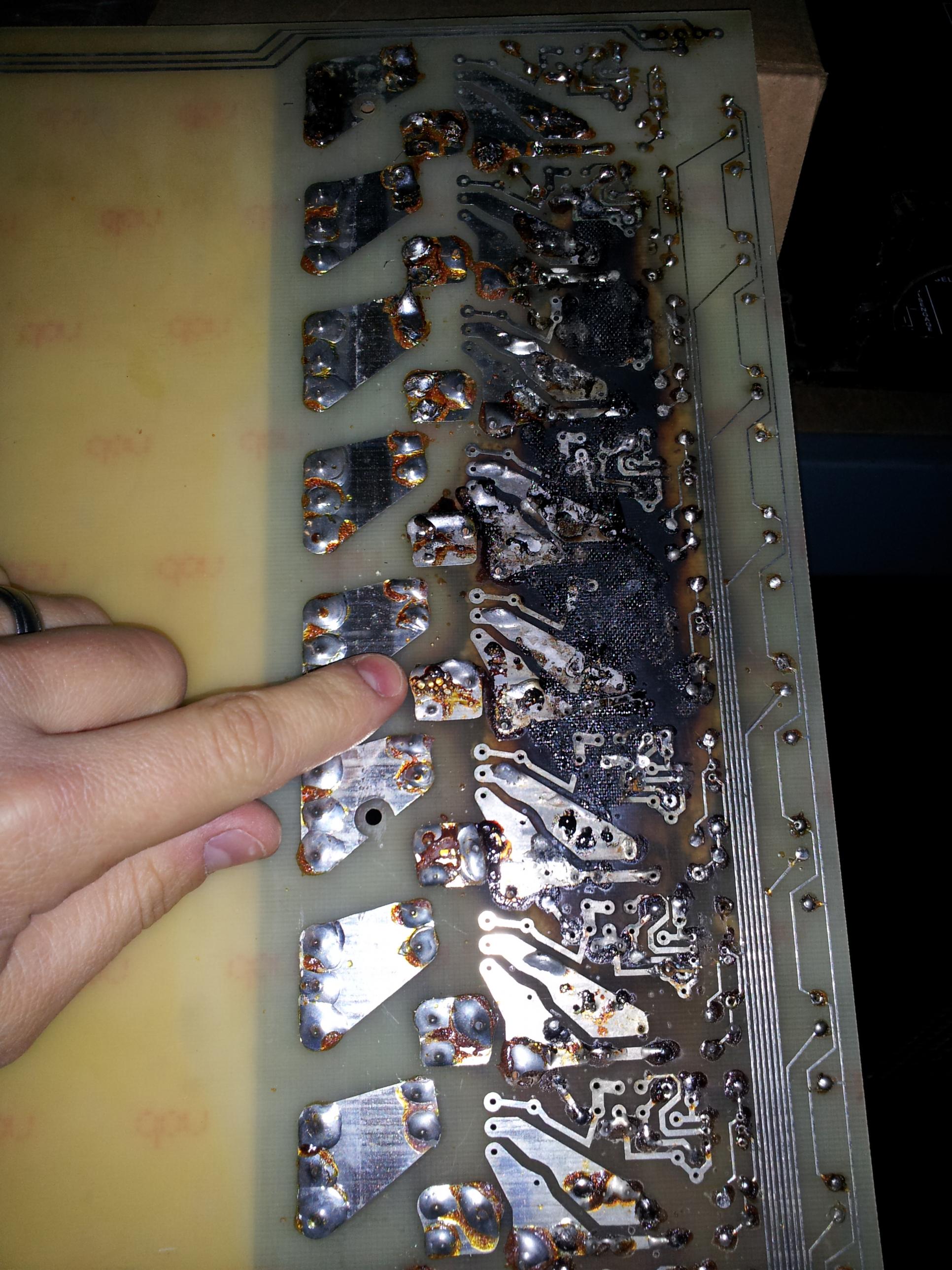
I have attached a photo of boards that I normally work on. Badly damaged, but fully repairable.
The second photo is the back side of the board B2375. If anyone with a CS-1000P could take a nice high resolution photo of the topside of the board it would be greatly appreciated. -
-
Thank you for your opinion ZLTFUL, but what I am actually looking for is the resistor value of R22 and R23 on board B2375.
-
When a board gets THAT HOT to actually melt the PCB something or someone did something that is WAY beyond normal. The second set of pictures show the first PCB that has been so hot that it bubbled plastic,flux and to my eyes made a mess way beyond any "repair" that should be made in any good faith....IT'S TOAST. Why were the resistors in the first photo? Why did that cap melt? Heck all those caps in that area looks like they went supernova. You mention that you contacted Polk CS they are the best on the planet. I and others think you are wasting time with that board.
all the info you need is right here on the forum
http://www.polkaudio.com/forums/showthread.php?38755-POLK-AUDIO-Speaker-Wiring-Schematics-amp-More-ALL-MODELS-except-SDA
http://www.polkaudio.com/forums/showthread.php?54252-Crossover-Diagram-for-CS1000P
all i did was google and got all the info you would need simple stuff so i hope you're better at repairing than searching for the answer that lies right before youe eyes.....
good luck have 911 on standby....
be sure to used the right resistors the ones you showed are not the right resistors. Let me suggest Mills 12w wire wound. -
pitdogg2,
Thank you for trying to help. Both documents that you have found are for the passive crossover. I have already found that information, and it does not apply to what I am trying to repair. The B2375 is part of the amplifier/ active crossover for the two subs. I bought this speaker second hand and can only assume that it was played way too loud for far too long. The resistors that I took out were 1/2 watt and the two that I put in the pic were 1/4 watt. I just wanted to see if it would turn on.
Attached is the correct schematic, it is just too blurry to read. -
Resistors generally burn up for a reason...2 Channel - Polk SDA-2BTL, Triad SA1, 1000VA Dreadnought, Ryff streaming via Control4 for Qobuz lossless audio
-
Kenneth Swauger can you clarify this I see what he means you can't tell squat on that schematic
-
Hello,
I'm working with Polk's CS guys to determine what they are.
Regards, Ken -
Thanks Ken.
-
Thank you Ken. If they have a higher resolution schematic available I would like a copy.
Cody -
pitdogg2,
Thanks for getting Ken for me. -
Hello,
Are you able to tell what the color bands are on the resistors?
Ken -
The resistors must be discolored, because I can't get the color code to work out.
Gray, White, Brown, Black. This doesn't work because black can't be the fourth band.
Black, Brown, White, Gray/Silver. This doesn't work because white can't be the third band.
I will have some pics in a minute.
Cody -
Polk's engineering guys are trying to see if they have a better copy.
-
Here are some pics. The brown band is not very red when compared to a new resistor with a red band.
-
Replace the board,easier that way,but backtrack to find out what caused it to fry! Probably too much current into the circuit! What dose the fried board control?
-
Kenneth Swauger,
Have you heard anything back from the engineering guys at Polk?
Cody -
I've just asked Polk if there's been any progress, so far.
-
I hope they have something soon!
-
They both are 680 Ohm 1 Watt resistors.
PM me your email address and I'll forward a better copy of the schematic. -
You are awesome! Thank you so much.


