Non-Common Ground Amp Question

GlennDog
Posts: 3,152
If the instructions below are correct, then my Adcom 5802 is common ground? I'm reading 0.285 ohms . . Now, I'm totally confused. Or is a reading of < 1 ohm considered so insignificant that it puts it into the Non-Common Ground Category? OR is there something wrong with the amp? (I hope not!!)
Thanks as always,
G
Check to see if it is a COMMON GROUND AMPLIFIER by doing the following -
The easiest way to tell if the amp is common ground is to take an ohm meter that is set to continuity and take one lead of the ohm meter and touch the neg terminal on the left output of the amp and take the other lead and touch the right negative terminal output of the amp and if it shows continuity you have a common ground amp, if nothing happens then you have a non-common ground amp. Basically the amp is considered a common ground if they share a ground for all the negative outputs on the amp.
AC Regenerator PS Audio PerfectWave Power Plant 10
Source Lumin U1 Mini into Lampizator Baltic 4 DAC
Pre Cary SLP-05
Power Rogue M180 Dark monos
Mains Salk HT2-TL
Rythmik F12
Source Lumin U1 Mini into Lampizator Baltic 4 DAC
Pre Cary SLP-05
Power Rogue M180 Dark monos
Mains Salk HT2-TL
Rythmik F12
Post edited by GlennDog on
Comments
-
~1/4 of one ohm is probably just fine. You do have the meter set to the lowest ohm scale, right? This isn't a decimal error because the meter is set to a higher-ohms scale, and it's really reading 2.85, 28.5, or 285 ohms?I'm reading 0.285 ohms
20 ohms will sound VERY terrible. I have experience with that. -
could be corrosion on the speaker terminals, or probe ends. Could Also be corrosion on internal connector or wiring. You can also get mixed results if not using the very tips of some probes. Best of luck.
-
I did have the dial one-up from the lowest setting. I lowered it from 2K to 200 ohms and it reads open/∞
So, no issues, right?
Thanks to the both of you, my mind is at ease!
GAC Regenerator PS Audio PerfectWave Power Plant 10
Source Lumin U1 Mini into Lampizator Baltic 4 DAC
Pre Cary SLP-05
Power Rogue M180 Dark monos
Mains Salk HT2-TL
Rythmik F12 -
STOP.I did have the dial one-up from the lowest setting. I lowered it from 2K to 200 ohms and it reads open/∞
So, no issues, right?
Thanks to the both of you, my mind is at ease!
G
You have it exactly backwards. You should be reading "0" resistance, not infinite resistance/open circuit.
I'm thinking your previous reading was .285 K ohms, or 285 ohms. This will be WAY TOO MUCH resistance/lack of continuity.
If you were showing 2 or 3 ohms, I'd say you need to zero the meter to remove the resistance of the test leads. At more than 200 ohms, that unit is NOT COMMON GROUND. -
The 5802 is NOT common ground. Just to clarify
I had a similar issue with a tube amp. It read fine at the terminals, plugged it into the main rig and got a bunch of high pitched squealing. Powered it down quickly and have been scratching my head. Haven't had time to revist the issue and/or multi-meter.
H9
EDIT--IT read as stated above, not zero but 2.**** Ohms"Appreciation of audio is a completely subjective human experience. Measurements can provide a measure of insight, but are no substitute for human judgment. Why are we looking to reduce a subjective experience to objective criteria anyway? The subtleties of music and audio reproduction are for those who appreciate it. Differentiation by numbers is for those who do not".--Nelson Pass Pass Labs XA25 | EE Avant Pre | EE Mini Max Supreme DAC | MIT Shotgun S1 | Puritan Audio PSM136 Pwr Condtioner & Classic PC's | Legend L600 | Roon Nucleus 1 w/LPS - Tubes add soul! -
I had a similar problem with a preamp/processor--although it did not show continuity with an ohmmeter. One of the RCA output jacks did not have the outer ring connected to ground. The resulting ground-loop through the interconnect cable shield put an enormous 60-cycle hum through the speakers. Properly attaching the ground to the RCA jack eliminated the noise.I had a similar issue with a tube amp. It read fine at the terminals, plugged it into the main rig and got a bunch of high pitched squealing. Powered it down quickly and have been scratching my head. Haven't had time to revist the issue and/or multi-meter.
H9
I suspect--but have not confirmed--that the Adcom can have the negative terminals strapped and then it will be a common-ground amp suitable for SDA speakers. A BRIDGED amp cannot be strapped, but I'm sure the Adcom is not bridged.
I did that with my "20 ohm" Aragon 8008BB. Made a world of difference! -
I double checked (but that doesn't make me/it right)
If my meter read the #1 In All Ranges, then there's an open. But it doesn't cuz in 2k setting, I'm registering a value. So there isn't an open. But it's not displaying a zero value either (in the lowest setting of 200 ohms).
What gives?
TY, againAC Regenerator PS Audio PerfectWave Power Plant 10
Source Lumin U1 Mini into Lampizator Baltic 4 DAC
Pre Cary SLP-05
Power Rogue M180 Dark monos
Mains Salk HT2-TL
Rythmik F12 -
If the instructions below are correct, then my Adcom 5802 is common ground?
None of Adcom's 5XXX series amps are common ground. They can be made common ground by connecting the negative terminals of each channel together with a piece of speaker wire that is the same gauge or larger than your speaker wire (strapping).Proud and loyal citizen of the Digital Domain and Solid State Country! -
There's more resistance than the meter can display in the 200-ohm range. Therefore it's showing "over limit" or infinite resistance in the 200-ohm range, but shows --I'm kinda guessing, here-- 285 ohms when set to the higher-ohms scale.
IF (Big IF) your meter was displaying ".285 Kohms" that would be .285 X 1000 or 285 ohms--more than can be displayed on a "200 ohm" setting.
Time to make a jumper. Two banana plugs or ring terminals, or whatever your amp will accept, and a foot or so of speaker wire or even automotive primary wire of 12--16 gauge (thicker wire preferred). -
Slightly off topic, DK would you know if the 3 channel Adcom 5503 in common or non-common? TY
Schurky, sir . . .And do what with it? Test the jumper to see if the meter is working properly?AC Regenerator PS Audio PerfectWave Power Plant 10
Source Lumin U1 Mini into Lampizator Baltic 4 DAC
Pre Cary SLP-05
Power Rogue M180 Dark monos
Mains Salk HT2-TL
Rythmik F12 -
Slightly off topic, DK would you know if the 3 channel Adcom 5503 in common or non-common? TYDarqueKnight wrote: »None of Adcom's 5XXX series amps are common ground.
Shove one cable end into the amplifier's LEFT CHANNEL negative output jack, shove the other end into the amplifier's RIGHT CHANNEL negative output jack. Now the negative jacks are connected together with a short length of cable (nearly 0 resistance if built correctly--so--yes--it would be worth checking with your meter), they become electrically connected--COMMON GROUND. You use whatever cable ends will work with your existing speaker wires, so that both the jumper wire and the negative speaker wire go to the negative post of the amp.Schurky, sir . . .And do what with it? Test the jumper to see if the meter is working properly?
Easy with my Aragon--there are two sets of output terminals for each channel. I use one set for the speaker wires, and the negative terminals of the second set for the jumper wire. If you only have one set per channel, you'll have two wires connected to the negative terminals--the speaker wire and the jumper wire. -
This question comes up from time to time. Here is a past thread with a direct quote from an email response from Adcom:
Polk SDA-SRS's-and-the-Adcom-5802
By the way, I have owned two 5802's and one 5503. I currently own one 5400 and four 5500's. I know from personal experience that they are all non-common ground.Proud and loyal citizen of the Digital Domain and Solid State Country! -
Correct it does not have a bridged ouytput stage but like your Aragon should have 20 ohm's between the negative terminals reflecting the 10 ohm resistor isolating each channels ground.A BRIDGED amp cannot be strapped, but I'm sure the Adcom is not bridged.
I did that with my "20 ohm" Aragon 8008BB. Made a world of difference! -
ok, here goes . . .
The Aragon must be non-common ground, right?
The Adcom has to set of similar outputs. One for "Normal" and one for "Bi-wire"
With a single piece of speaker wire, I jumped from Normal Left Neg to Normal Right Neg and then measured from the Bi-wire Left Neg to Bi-wire Right Neg and the reading is 0.1 - 0.2 on the 200 ohm range setting and then 0.000 on the 2K range . . .
The manual for the multi-meter says "the ohm meter is sensitive enough to read the resistance of the test leads. When testing in the 200 ohm range, touch the test leads together and note the displayed reading and subtract that value from the test result"
I did so, and subtracted the 0.1 - 0.2 . . . and the skies are blue again !
THANKS!!!AC Regenerator PS Audio PerfectWave Power Plant 10
Source Lumin U1 Mini into Lampizator Baltic 4 DAC
Pre Cary SLP-05
Power Rogue M180 Dark monos
Mains Salk HT2-TL
Rythmik F12 -
Another question . . . In lieu of the Dreadnaught AI-1, (or the famed AV-47548) I can jumper the negative posts as mentioned above and run my speaker wire as one would normally do?
Again, THANKS!
GAC Regenerator PS Audio PerfectWave Power Plant 10
Source Lumin U1 Mini into Lampizator Baltic 4 DAC
Pre Cary SLP-05
Power Rogue M180 Dark monos
Mains Salk HT2-TL
Rythmik F12 -
Yes.Another question . . . In lieu of the Dreadnaught AI-1, (or the famed AV-47548) I can jumper the negative posts as mentioned above and run my speaker wire as one would normally do?
Again, THANKS!
G -
If there's a pair of 10-ohm resistors in there...I haven't found them. I have no idea why there's 20 ohms between the negative terminals. Aragon claims it's part of the safety features built-into the amp, but refuse to specify what safety issue they're designed to alleviate. All I know is that the jumper is needed with my speakers, it's been there for years, and the amp hasn't burned up yet.Correct it does not have a bridged ouytput stage but like your Aragon should have 20 ohm's between the negative terminals reflecting the 10 ohm resistor isolating each channels ground.
Semi-non-common ground?ok, here goes . . .
The Aragon must be non-common ground, right?
Partial common ground?
There is some continuity between the grounds, but it's enough resistance to play hell with my 1Bs. Another member has an Aragon 8008BB, and his would shut down when used with his SDAs--but I don't remember which SDAs he had. He fixed the problem first with a jumper like I use, then went to the "Dreadnought" AI-1, and claimed the sonics were even better with the AI-1.
Yup.The Adcom has to set of similar outputs. One for "Normal" and one for "Bi-wire"
With a single piece of speaker wire, I jumped from Normal Left Neg to Normal Right Neg and then measured from the Bi-wire Left Neg to Bi-wire Right Neg and the reading is 0.1 - 0.2 on the 200 ohm range setting and then 0.000 on the 2K range . . .
The manual for the multi-meter says "the ohm meter is sensitive enough to read the resistance of the test leads. When testing in the 200 ohm range, touch the test leads together and note the displayed reading and subtract that value from the test result"
I did so, and subtracted the 0.1 - 0.2 . . . and the skies are blue again !
THANKS!!!
Yes. That's the whole point of the jumper wire--to create a common ground where it didn't exist before.Another question . . . In lieu of the Dreadnaught AI-1, (or the famed AV-47548) I can jumper the negative posts as mentioned above and run my speaker wire as one would normally do?
Again, THANKS!
G -
The Adcom has a pair of 10 ohm resistors which will give it the same 20 ohms between the negative terminals as you measured with your Aragon.I can only speculate Aragon has done similar since as with the Adcom you can create a common ground by adding the jumper wire,which effectively bypasses the resistors.If there's a pair of 10-ohm resistors in there...I haven't found them. -
Well the resistors are likely tying circuit ground to chassis ground or safety ground as per UL regulations.Instead of a direct connection to the chassis which could create ground loop issues,small value resistors are used which makes the required ground connection while at the same time providing enough isolation to lessen the potential for ground loops.... no idea why there's 20 ohms between the negative terminals. Aragon claims it's part of the safety features built-into the amp, but refuse to specify what safety issue they're designed to alleviate. -
Thank you for that.Well the resistors are likely tying circuit ground to chassis ground or safety ground as per UL regulations.Instead of a direct connection to the chassis which could create ground loop issues,small value resistors are used which makes the required ground connection while at the same time providing enough isolation to lessen the potential for ground loops.
Seems like one could tie the speaker terminals together ahead of the resistors (inside the cabinet) and have the best of all worlds. I suppose then they couldn't advertise "Dual Monobloc in one chassis", since the channels would share the resistors. -
I measured the resistance between the negative terminals of three of my Adcom amps with a Fluke 8050A multimeter. The meter subtracts the lead resistance from the measurement:
GFA-5500 #1, 14.65 ohms.
GFA-5500 #2, 10.86 ohms.
GFA-5400, 11.46 ohms.Proud and loyal citizen of the Digital Domain and Solid State Country! -
I suspect you have accomplished such jumpering externally as there should still be some resistance between circuit ground and chassis ground.However the addition of the jumper should place the resistors in parallel so you should now have about 5 ohms between chassis ground and each negative terminal.To confirm you could meter from the ground lug of your AC cord and each negative speaker terminal..
Seems like one could tie the speaker terminals together ahead of the resistors (inside the cabinet) and have the best of all worlds. -
DarqueKnight wrote: »I measured the resistance between the negative terminals of three of my Adcom amps with a Fluke 8050A multimeter. The meter subtracts the lead resistance from the measurement:
GFA-5500 #1, 14.65 ohms.
GFA-5500 #2, 10.86 ohms.
GFA-5400, 11.46 ohms.
DK- I have been following this thread with interest because I just purchased a pair of Polk 2.3TL's and have an Adcom 5400 amp I was considering driving them with. Using a basic Craftsman digital multimeter, I measure 7.5 ohms between the negative posts. After creating a basic speaker wire jumper of 12" length 14ga wire and putting thru the holes in the binding posts, I remeasured and got .3 ohms. My meter does not account for leads resistance.
Does this look accurate to you, and will I be safe in using this amp with the 2.3TL's with the wire jumper in place?
Thanks,
Travis2-ch System: Parasound P/LD 2000 pre, Parasound HCA-1000 amp, Parasound T/DQ Tuner, Phase Technology PC-100 Tower speakers, Technics SL-1600 Turntable, Denon 2910 SACD/CD player, Peachtree DAC iT and X1asynchorus USB converter, HSU VTF-3 subwoofer. -
Per instructions from Adcom, any of the 5XXX series amps will work with SDA's if the ground terminals connected together. The 0.3 ohms you measured with the jumper is place is the meter lead resistance.Proud and loyal citizen of the Digital Domain and Solid State Country!
-
That is what I figured from reading the email you posted earlier, just saw some differance in measurements of my 5400 vs your 5400 and wanted to confirm it was within spec. TY2-ch System: Parasound P/LD 2000 pre, Parasound HCA-1000 amp, Parasound T/DQ Tuner, Phase Technology PC-100 Tower speakers, Technics SL-1600 Turntable, Denon 2910 SACD/CD player, Peachtree DAC iT and X1asynchorus USB converter, HSU VTF-3 subwoofer.
-
That is what I figured from reading the email you posted earlier, just saw some differance in measurements of my 5400 vs your 5400 and wanted to confirm it was within spec. TY
What is not commonly known is that there are two versions of the GFA-5400. I have version 2. This quote is from the GFA-5400 service manual:
"There are 2 versions of the GFA-5400 amplifier. The primary difference between the original version 1 and the updated version 2 is the addition of the ADCOM output protection circuit in version 2. This circuit can be noted by comparing the schematics of both versions in this manual. The power transformer, speaker binding posts and input jacks are also unique to each version."
Figures 1-3 below illustrate the version 1 and version 2 differences. Although not mentioned in the service manual, the vent holes and screw pattern of the case top cover are different between the version 1 and version 2 shown below.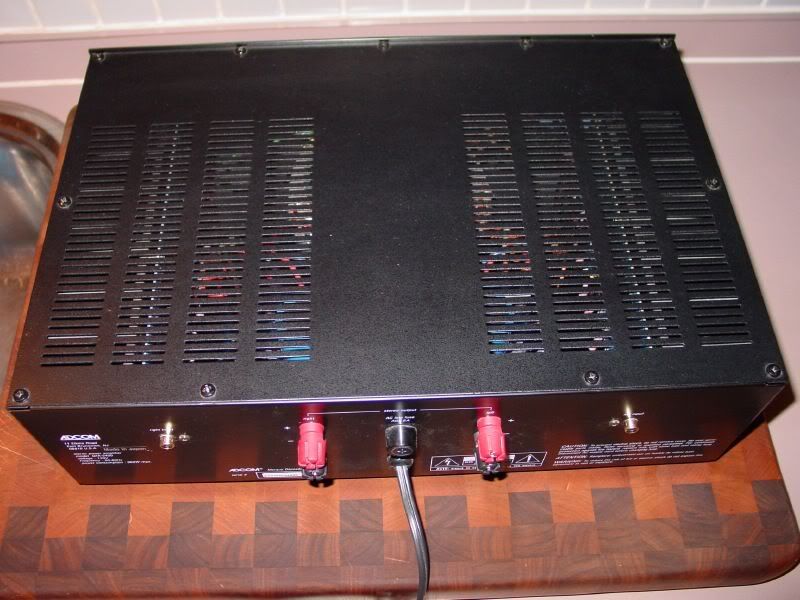
Figure 1. Adcom GFA-5400 version 1 top and rear. Each version 1 binding post is mounted in a separate
circular red or black plastic housing. For version 2, the positive and negative binding posts of each channel
are mounted in a single long oval black plastic housing.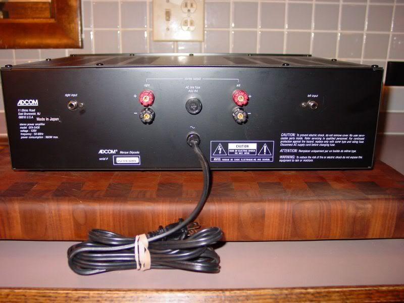
Figure 2. Adcom GFA-5400 version 1 rear.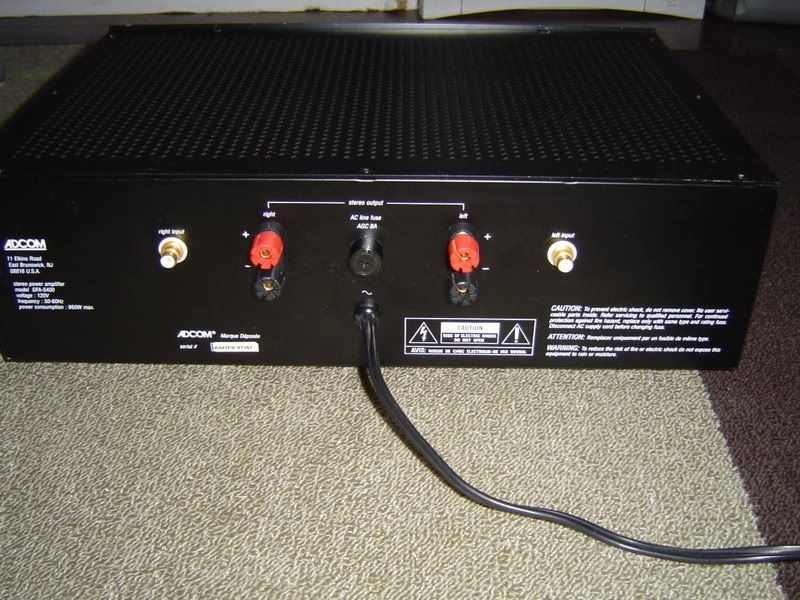
Figure 3. Adcom GFA-5400 version 2 rear.
There are also two versions of the GFA-5500: a 120 volt version 1 with a captive power cord and a convertible 120/230 volt version 2 with a detachable IEC power cord. All four of my 5500's are version 2, but there was a significant negative terminal resistance difference between the 5500 that is in storage and the 5500 that is shown at the lower right in figure 5. There may have been some publicly undocumented parts changes to the 5500 version 2 that accounts for the difference.DarqueKnight wrote:GFA-5500 #1, 14.65 ohms.
GFA-5500 #2, 10.86 ohms.
Parts changes might also explain the significant resistance difference you measured if your 5400 is a version 2.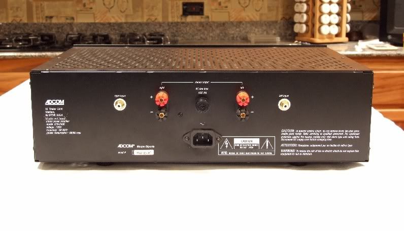
Figure 4. My GFA-5400 version 2 is slightly different due to the replacement of the captive power cord with
an IEC jack.
I was curious about the resistance between the negative binding posts of the other two 5500's, but I would have had to pull the 9 ton cabinet from the wall to access their binding posts. I'll defer that strenuous exercise to the future...when I'm more dedicated to audio than I am now.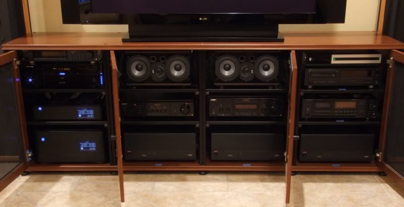
Figure 5. Adcom GFA-5500 version 2's in home theater equipment cabinet.Proud and loyal citizen of the Digital Domain and Solid State Country! -
I was curious about the resistance between the negative binding posts of the other two 5500's, but I would have had to pull the 9 ton cabinet from the wall to access their binding posts. I'll defer that strenuous exercise to the future...when I'm more dedicated to audio than I am now. -- DK
^ Slacker:razz: jk
Thanks for the info and update. My 5400 is a ver 1 so that and your power cord upgrade may explain the differance. I tested last night briefly using a small walkman cd player w/ volumne control as source thru the Adcom and it did fine with the 2.3's. Will be revamping my whole entertainment rack and 2ch rig this weekend.2-ch System: Parasound P/LD 2000 pre, Parasound HCA-1000 amp, Parasound T/DQ Tuner, Phase Technology PC-100 Tower speakers, Technics SL-1600 Turntable, Denon 2910 SACD/CD player, Peachtree DAC iT and X1asynchorus USB converter, HSU VTF-3 subwoofer. -
My 5400 is a ver 1 so that and your power cord upgrade may explain the differance.
The power cord mod would have had no effect on the binding post resistance. Besides, the power cord, as well as the speaker cables and interconnects, were disconnected when I did the resistance measurements.Proud and loyal citizen of the Digital Domain and Solid State Country!


