Loudspeaker Inductor Crosstalk Measurements

DarqueKnight
Posts: 6,765
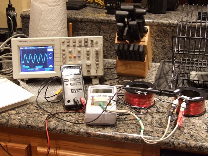
Figure 1. Inductor crosstalk test setup. (Note: this grouping is only for the photo. To avoid any interference from the
oscilloscope or its power cord, the oscilloscope was placed four feet from the inductors.)
Introduction
A study was done to measure the effects of inductive coupling (crosstalk) between two large inductors (nominal 16 mH) taken from a pair of Polk Audio SDA SRS 1.2TL loudspeakers. The inductor spacing arrangements were taken from a study done by Troels Gravesen in 2009 (forwarded to me by forum member Janne).
This report and the Gravesen report may be of interest to those who have done, or are planning to do, a loudspeaker inductor upgrade.
Test Apparatus
Tektronix Digital Sampling Oscilloscope, Model # TDS 2012
MCP LCR Meter, Model # BR2822
Radio Shack Digital Multimeter (used to double check voltage measurements from oscilloscope)
Air Core Inductor #1, 15.5 mH
Air Core Inductor #2, 15.4 mH
The inductors were wound on plastic spools measuring 5.33 cm. (2.1 in.) high by 10.2 cm. (4 in.) in diameter.
Test Procedure
In inductance measurement mode, the LCR meter can output four different frequencies: 100 Hz, 120 Hz, 1,000 Hz, 10,000 Hz.
The LCR meters output voltages at the various frequencies were measured under no load (not connected to an inductor) and under load (connected to inductor #1) conditions using the oscilloscope.
Table 1. LCR Meter Output Voltage Under Load and No Load Conditions


Inductor #1 was connected to the leads of the LCR meter. Inductor #2 was connected to the leads of the oscilloscope. The spacing patterns used were taken from the Troels study as shown in figure 2.
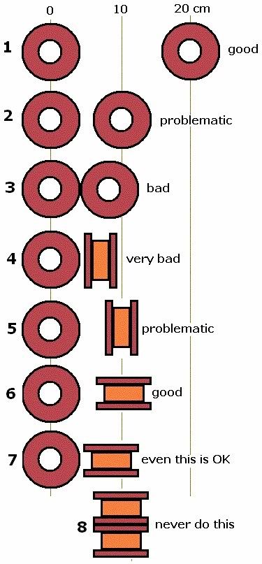
Figure 2. Inductor spacing.
Due to the 10.2 cm inductor spool diameter, the 10 cm. (4 in.) and 20 cm. (8 in.) spacings were increased to 15 cm. (6 in.) and 30 cm. (12 in.). Otherwise, arrangement #2 in figure 2 could not have been done as the spools would have been positioned right next to each other as in arrangement #3 of figure 2.
The LCR meter was switched through the four output frequencies while it was connected to inductor #1 and output voltage measurements were taken by the oscilloscope while it was connected to inductor #2. The oscilloscope was reset and allowed to settle for 30 seconds prior to taking each voltage measurement. The worst case position (#8) was first measured with inductor #1 stacked directly on top of inductor #2 and again stacked with a 1.9 cm MDF board between them.
Table 2. Crosstalk measurements at 100 Hz, input voltage at Inductor #1 = 0.35 V.
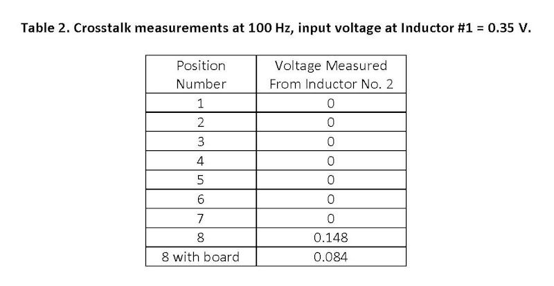
Table 3. Crosstalk measurements at 120 Hz, input voltage at Inductor #1 = 0.415 V.
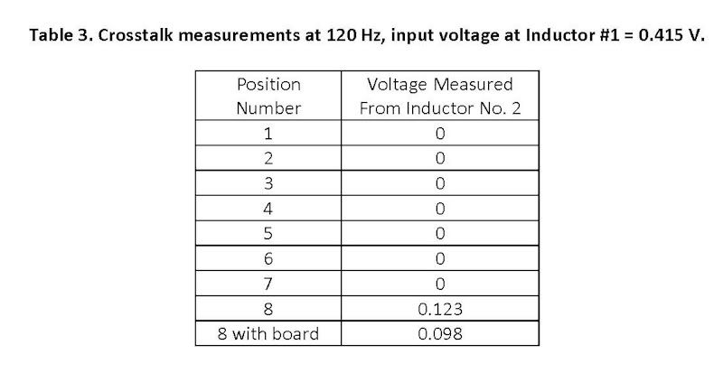
Table 4. Crosstalk measurements at 1,000 Hz, input voltage at Inductor #1 = 02.35 V.
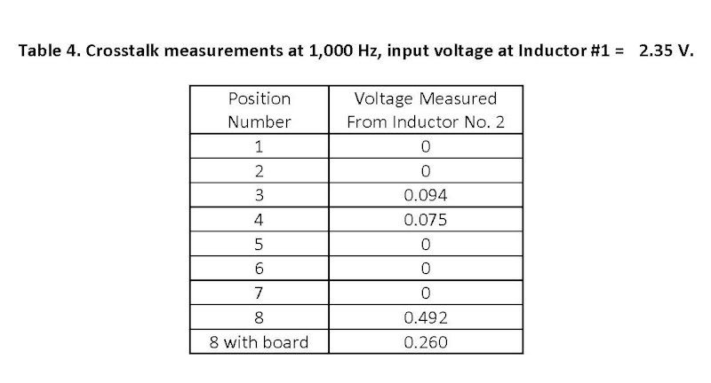
Table 5. Crosstalk measurements at 10,000 Hz, input voltage at Inductor #1 = 2.45 V.
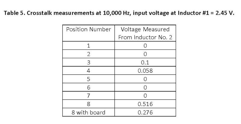

Table 3. Crosstalk measurements at 120 Hz, input voltage at Inductor #1 = 0.415 V.

Table 4. Crosstalk measurements at 1,000 Hz, input voltage at Inductor #1 = 02.35 V.

Table 5. Crosstalk measurements at 10,000 Hz, input voltage at Inductor #1 = 2.45 V.

Discussion of Results
At low frequencies (100 and 120 Hz), crosstalk (induced voltage) was only measurable with the worst case position #8. At 100 Hz, the induced voltage in inductor #2 was 42% of inductor #1s voltage. Placing a 1.9 cm. (0.75 in.) MDF board between the stacked inductors reduced inductor #2s induced voltage by nearly half, to 24% of inductor #1s voltage.
At 120 Hz, the induced voltage in inductor #2 was 30% of inductor #1s voltage. Placing a 1.9 cm MDF board between the stacked inductors reduced inductor #2s induced voltage to 24% of inductor #1s voltage.
At 1,000 Hz, crosstalk in inductor #2 was only measurable in positions 3, 4 and 8. At position #3, the induced voltage in inductor #2 was 4% of inductor #1s voltage. At position #4, the induced voltage in inductor #2 was 3% of inductor #1s voltage. At position #8, the induced voltage in inductor #2 was 21% of inductor #1s voltage. Placing a 1.9 cm MDF board between the stacked inductors reduced inductor #2s induced voltage to 11% of inductor #1s voltage.
At 10,000 Hz, crosstalk in inductor #2 was only measurable in positions 3, 4 and 8. At position #3, the induced voltage in inductor #2 was 4% of inductor #1s voltage. At position #4, the induced voltage in inductor #2 was 2.3% of inductor #1s voltage. At position #8, the induced voltage in inductor #2 was 21% of inductor #1s voltage. Placing a 1.9 cm MDF board between the stacked inductors reduced inductor #2s induced voltage to 11% of inductor #1s voltage.
As one of Mr. Gravesens readers mentioned:
"In my opinion, you measurements about the placement of coils won't show the whole truth or the real problem of placing coils next to each other. The real problem is the crosstalk, not the change in inductivity (although this is a little problem, too, even though the changes in inductivity stay below 10 %). It would be great if you could do the measurements again, but this time measure the crosstalk, too. You could do this by giving one coil a 50 Hz signal with a defined voltage and measuring the output voltage on the other coil."
The measurements taken in this study indicate that crosstalk is mainly an issue when inductors are stacked directly on top of one another (position #8), positioned horizontally adjacent to each other (position #3) or positioned perpendicularly such that their magnetic fields are not at right angles (position #4). Even in the worst case stacked configuration, crosstalk can be significantly reduced by a small spacing of 1.9 cm (thickness of the MDF board).
The input voltages of 0.35 to 2.45 are representative of the steady state and peak voltages that a loudspeaker inductor might encounter in actual use when listening at a moderate level (typically 85-90 dB-C, 10 or 11 o'clock on the volume knob).
Reference
Troels Gravesen, Placement of coils in crossover networks, http://www.troelsgravesen.dk/coils.htm, 2009, accessed 1/05/2011.
Proud and loyal citizen of the Digital Domain and Solid State Country!
Post edited by DarqueKnight on
Comments
-
Hey, this is a great write-up and good info when mod'ing and building XO's.
Stan
PS. I have to ask, do you always do your best work in the kitchen? Also, is that a Nikon D70(s)? And don't you hate when folks scrutinize posted photos?Stan
Main 2ch:
Polk LSi15 (DB840 upgrade), Parasound: P/LD-1100, HCA-1000A; Denon: DVD-2910, DRM-800A; Benchmark DAC1, Monster HTS3600-MKII, Grado SR-225i; Technics SL-J2, Parasound PPH-100.
HT:
Marantz SR7010, Polk: RTA11TL (RDO198-1, XO and Damping Upgrades), S4, CS250, PSW110 , Marantz UD5005, Pioneer PL-530, Panasonic TC-P42S60
Other stuff:
Denon: DRA-835R, AVR-888, DCD-660, DRM-700A, DRR-780; Polk: S8, Monitor 5A, 5B, TSi100, RM7, PSW10 (DXi104 upgrade); Pioneer: CT-6R; Onkyo CP-1046F; Ortofon OM5E, Marantz: PM5004, CD5004, CDR-615; Parasound C/PT-600, HCA-800ii, Sony CDP-650ESD, Technics SA 5070, B&W DM601 -
PS. I have to ask, do you always do your best work in the kitchen?
It's either the kitchen, the garage or my lab at work. The kitchen is closest to my audio toys and is much more comfortable. Also, is that a Nikon D70(s)?
It is a Nikon D700. I am doing comparisons between my old 85mm f/1.4D lens and my new 85mm f/1.4G lens.And don't you hate when folks scrutinize posted photos?
Not at all. I do the same thing, since, as you've noticed, I have some interest in photography.Proud and loyal citizen of the Digital Domain and Solid State Country! -
Well....I am to ignorant on the subject to comment on what you are doing there. But those are some damn nice looking counter tops! :cool:--Gary--
Onkyo Integra M504, Bottlehead Foreplay III, Denon SACD, Thiel CS2.3, NHT VT-2, VT-3 and Evolution T6, Infinity RSIIIa, SDA1C and a few dozen other speakers around the house I change in and out. -
For whatever reason I cannot see the photos. Can they be downloaded in a different way?
madmaxVinyl, the final frontier...
Avantgarde horns, 300b tubes, thats the kinda crap I want...
-
If refreshing your browser does not work and assuming you are using Internet Explorer:
1. Right click on the post number to open it in a new tab or window.
2. From the "View" menu, click on "Source"
3. Click on the "Edit" menu then "Find"
4. Type in "bucket" to find links to the photos that are hosted on photobucket.com.
5. Cut and paste the links.
Sometimes, right clicking on the "X" where a photo should be and then selecting "show picture" works.Proud and loyal citizen of the Digital Domain and Solid State Country! -
Damn, Raife. The ONE thing I didn't think I needed to pay attention too and now this.....
I hate you. I really, really hate you....said in a most respectful way.....
Dang, just when you thought you had your plan down.....~ In search of accurate reproduction of music. Real sound is my reference and while perfection may not be attainable? If I chase it, I might just catch excellence. ~ -
I hate me too...and my wallet hates me most of all. He just doesn't understand.:frown:Proud and loyal citizen of the Digital Domain and Solid State Country!
-
Nice write up.... If anyone quotes it in its entirety, I might be driven to violence.
raife,
You do realize that t3 and a few dozen other polkies will be SDA diving within days... personally, I think you do it on purpose.
When you wrote about the oscilloscope (cute little fella) settling time was this for the scope or the coil's voltage lag?More later,
Tour...
Vox Copuli
Better to remain silent and be thought a fool, than to open your mouth and remove all doubt. - Old English Proverb
"Death doesn't come with a Uhaul." - Dennis Gardner
"It's easy to get lost in price vs performance vs ego vs illusion." - doro
"There is a certain entertainment value in ripping the occaisonal (sic) buttmunch..." - TroyD -
Nice write up.... If anyone quotes it in its entirety, I might be driven to violence.
If I don't regularly release the random high pressure SDA-related thoughts that build up in my brain...I might be driven to violence.:eek:You do realize that t3 and a few dozen other polkies will be SDA diving within days... personally, I think you do it on purpose.
I do. I go SDA diving almost daily. It's good exercise. When you wrote about the oscilloscope (cute little fella) settling time was this for the scope or the coil's voltage lag?
Both, but more so for the 'scope. The act of breaking and making an electrical connection is somewhat unsettling for some oscilloscopes. Sort of like being rudely awakened from a sound sleep.Proud and loyal citizen of the Digital Domain and Solid State Country! -
Certainly one would want to reduce the tendancies of all the inductors to talk to each other,but I think the most potentially sonically degrading would be in the case of the low pass coils inducing there signal on to that of the tweeters.Therefore IMO even greater care should be taken to insure optimum placement of the coils in the low pass in relation to those in the hi pass vs coil- coil in the low pass section, otherwise I suspect hi frequency clarity would be compromised to some extent.
With such a system experimenting by removing the amp feed to the high pass filter (but leaving woofer connected) would likely result in the tweeter still producing some output even though it isn't connected to the amp. -
Great thread; good info. Thank you~TNRabbit
NO Polk Audio Equipment :eek:
Sunfire TG-IV
Ashly 1001 Active Crossover
Rane PEQ-15 Parametric Equalizers x 2
Sunfire Cinema Grand Signature Seven
Carver AL-III Speakers
Klipsch RT-12d Subwoofer -
Excellent study. I was most surprised by this:DarqueKnight wrote: »
The input voltages of 0.35 to 2.45 are representative of the steady state and peak voltages that a loudspeaker inductor might encounter in actual use when listening at a moderate level (typically 85-90 dB-C, 10 or 11 o'clock on the volume knob).
I have read that the preamplifier output was usually in the 0-2v range, just expected that the main amplifier output was greater than this, something at least in the range of 8-12 volts for normal listening. Especially in midrange circuits where the inductor is the first component in the crossover signal path. Now it makes all the more sense why having a high current output on an amplifier is so important. -
This is EXACTLY one of the reasons I went to active bi-amping & removed the passive crossovers in my speakers~TNRabbit
NO Polk Audio Equipment :eek:
Sunfire TG-IV
Ashly 1001 Active Crossover
Rane PEQ-15 Parametric Equalizers x 2
Sunfire Cinema Grand Signature Seven
Carver AL-III Speakers
Klipsch RT-12d Subwoofer -
This is EXACTLY one of the reasons I went to active bi-amping & removed the passive crossovers in my speakers~
I agree, zero EMF/RF Leakage etc... at that point. What are you using as your active x-over?
My current DIY build has the tweeter, mid, woofers all on separate boards. Still debating if they are going in cabinet or not. -
I agree, zero EMF/RF Leakage etc... at that point. What are you using as your active x-over?
My current DIY build has the tweeter, mid, woofers all on separate boards. Still debating if they are going in cabinet or not.
Ashly crossover; it's all chronicled HERETNRabbit
NO Polk Audio Equipment :eek:
Sunfire TG-IV
Ashly 1001 Active Crossover
Rane PEQ-15 Parametric Equalizers x 2
Sunfire Cinema Grand Signature Seven
Carver AL-III Speakers
Klipsch RT-12d Subwoofer -
Ashly crossover; it's all chronicled HERE
Thx, I remember that thread now. You have to love pro-gear like active x-overs:biggrin: -
Tried to view pics here, got a blank screen that says "Done"...
http://i148.photobucket.com/albums/s23/darqueknight88/InductorXtalk/InductorCrosstalkStudy-s.jpg
Maybe its blocked here or something.Vinyl, the final frontier...
Avantgarde horns, 300b tubes, thats the kinda crap I want...
-
But the crosstalk issue can be nullified by proper placement.On the other hand as a diehard active speaker builder/user myself I believe there are a number of other performance areas in which active crossovers if properly done can have advantages over passives.This is EXACTLY one of the reasons I went to active bi-amping & removed the passive crossovers in my speakers~
I 'll disagree,I think the additional cabling and the extra electronics required in an active crossover set up would potentially be more prone to RFI/EMI issues than inductors in a loudspeaker.IMO since the large magnitude of the signal in a passive crossover and in the speaker wires the level of RFI/EMI would be so minute in comparison as to not be an issue.However RFI/EMI can be an issue with the much lower voltages involved at the preamp/active crossover level.I agree, zero EMF/RF Leakage etc... at that point. . -
Nothing is better than data and DK is commended again for his work! As stated in the OP, this will likely be helpful for those who rebuild x-overs. My question is what the "real-life crosstalk" is in, e.g. the original 1.2 TL X-over? Distances between inductors are smaller and there is only one 16 mH (IIRC) per x-over. Is there a difference in crosstalk between a 2 and 16 mH vs 2 16mH as in the experiment? I don't know and don't have the equipment to find out. If anyone does ever do this, it would be important data for the recent discussions on the new X-over pcb's. Maybe this is obsessive, but maybe that's why it's posted! :biggrin:
Thanks for the data. Don't ya just love good science? -
I 'll disagree,I think the additional cabling and the extra electronics required in an active crossover set up would potentially be more prone to RFI/EMI issues than inductors in a loudspeaker.IMO since the large magnitude of the signal in a passive crossover and in the speaker wires the level of RFI/EMI would be so minute in comparison as to not be an issue.However RFI/EMI can be an issue with the much lower voltages involved at the preamp/active crossover level.
That depends. For myself, if I go fully active, you can be guaranteed that it would be a fully balanced setup. That is the whole point (noise rejection). So in this instance a shielded balanced cable is just the ticket.
EMF would also without a doubt be a non-issue. -
Well I didn't say it will be a problem,and I use only single ended cabling and have no problems.My point is that RFI is really a non issue at the speaker level because of the high signal levels involved should swamp it.Whereas it could be an issue with low level signals.That depends. For myself, if I go fully active, you can be guaranteed that it would be a fully balanced setup. That is the whole point (noise rejection). So in this instance a shielded balanced cable is just the ticket.
EMF would also without a doubt be a non-issue. -
I will too the day I can afford a DEQX and 6 channel W4S amp. :biggrin:This is EXACTLY one of the reasons I went to active bi-amping & removed the passive crossovers in my speakers~"He who fights with monsters should look to it that he himself does not become a monster. And when you gaze long into an abyss the abyss also gazes into you." Friedrich Nietzsche -
Did you try to foil wrap them to see if it helps?
Just wondering because a friend made his own speakers and had a problem with multiple coils and wrapped them in foil. He said it worked but I never saw any real data on the subject. -
Outfitter03 wrote: »Excellent study. I was most surprised by this:
I have read that the preamplifier output was usually in the 0-2v range, just expected that the main amplifier output was greater than this, something at least in the range of 8-12 volts for normal listening. Especially in midrange circuits where the inductor is the first component in the crossover signal path. Now it makes all the more sense why having a high current output on an amplifier is so important.
Here are some measurements with two amplifiers and three sets of SDA loudspeakers.
Measurements were taken with the music playing at an average level of 90 dB-C. The music was "Diane's Blues" from George Howard's "The Very Best of George Howard" CD. The song has moderately heavy bass content.
Measurement Tools:
Radio Shack Digital Multimeter
Fluke Model 322 Clamp Meter
Radio Shack Analog Sound Level Meter
Home Theater System Measurements:
Amplifier: Adcom GFA-5500 (350 watts continuous into 4 ohms)
Preamplifier: Sony TA-P9000ES
Loudspeaker: Polk Audio SDA CRS+, 6 ohms nominal impedance.
Preamp volume at 10 for 90 dB-C average sound level.
AC volts at left speaker + lead: 0.22 V to 2.9 V, with peaks at 4 V, 12 V and occasionally 42 V.
AC current at left speaker + lead: 0.01 A to 0.33 A, with peaks from 0.6 A to 0.75 A
AC volts at left speaker SDA cable: 0.9 V to 2.2, with peaks at 3.3 V.
AC current at left speaker SDA cable: 0.03 A to 0.12 A.
Loudspeaker: Polk Audio SDA SRS, 4 ohms nominal impedance.
Preamp volume at 9.5 for 90 dB-C average sound level.
AC volts at left speaker + lead: 0.6 V to 2.5 V, with peaks at 3.5 V.
AC current at left speaker + lead: 0.06 A to 0.32 A, with peaks from 0.44 A to 0.67 A
Due to the custom XLR two conductor SDA cable, I could not take voltage and current and measurements at the SDA jack. I would need a special adapter providing uninsulated terminals and separation for the wires.
Two Channel Audio System Measurements
Amplifier: Parasound Halo JC 1 (400 watts continous into 8 ohms)
Preamplifier: Pass Labs X0.2
Loudspeaker: Polk Audio SDA SRS 1.2TL, 6 ohms nominal impedance.
Preamp volume at 29 for 90 dB-C average sound level.
AC volts at right speaker + lead: 0.32 V to 1.9 V, with peaks at 2.5 V and 3.3 V.
AC current at right speaker + lead: 0.05 A to 0.16 A, with peaks at 0.22 A
AC volts at left speaker SDA cable: 0.18 V to 1.1 V, with peaks at 2.2 V.
AC current at left speaker SDA cable: 0.02 A to 0.07 A, with peaks at 0.1 A.
***Bear in mind that these consumer grade measurment tools are not fast enough to capture the many much higher level current and voltage transients that occur during music playback.***Did you try to foil wrap them to see if it helps?
Just wondering because a friend made his own speakers and had a problem with multiple coils and wrapped them in foil. He said it worked but I never saw any real data on the subject.
I have wrapped transformers in foil and it significantly reduced noise caused by environmental sources. See post #3 figures 33-39 of this thread. I have not tried it with inductors.Tried to view pics here, got a blank screen that says "Done"...
http://i148.photobucket.com/albums/s23/darqueknight88/InductorXtalk/InductorCrosstalkStudy-s.jpg
Maybe its blocked here or something.
Photobucket must have a reputation for hosting naughty pics. Proud and loyal citizen of the Digital Domain and Solid State Country!
 -
Just how little power is supplied at normal listening levels never fails to astound
Just how much reserve is needed at synphony listening levels never fails to astoundDarqueKnight wrote: »Both, but more so for the 'scope. The act of breaking and making an electrical connection is somewhat unsettling for some oscilloscopes. Sort of like being rudely awakened from a sound sleep.
Surprises me since it appears to be new era, SS, LCD scope... yet it behaves like the tubed, bigger-than-a-breadbox scopes of my 70's, P-lab days...More later,
Tour...
Vox Copuli
Better to remain silent and be thought a fool, than to open your mouth and remove all doubt. - Old English Proverb
"Death doesn't come with a Uhaul." - Dennis Gardner
"It's easy to get lost in price vs performance vs ego vs illusion." - doro
"There is a certain entertainment value in ripping the occaisonal (sic) buttmunch..." - TroyD -
Reported, you lousy spammer of handbags. I don't think this is a big
handbag buying crowd.
On topic, this is why running Linn stuff in full "activ" mode sounds
so good. It's a shame someone else doesn't design for a full non-xover
amp based set up. Doing it at the amp level sure seems to make more
sense."The legitimate powers of government extend to such acts only as are injurious to others. But it does me no injury for my neighbour to say there are twenty gods, or no god. It neither picks my pocket nor breaks my leg." --Thomas Jefferson


