Polk Monitor 7A - A Different sort of Restoration... (With Pictures!)

Private_Idaho
Posts: 21
Wow, it's been nearly 2 years already since I posted this thread on how I should approach bringing my (new to me at the time) Polk Monitor 7As back to life after they had been hacked up pretty bad: https://forum.polkaudio.com/discussion/200391/monitor-7a-resurrection-advice-needed#latest
Time really does fly. Well in that time, a lot happened that put these speakers on the back burner for me for quite some time, until now...
This is my first pair of Monitor 7 speakers. I am very excited to hear them for the first time. Before I get too into detail here I will say that these will be on garage duty, so unfortunately a full cosmetic restoration is not quite in order for these at this time. Also it's worth noting that due to space constraints, I will not be putting these on their proper stands (they did not come with stands when I purchased them anyways). Instead, they will live on some shelves I made and mounted to opposing ends of one of the walls in my garage. But don't worry, there's still plenty to unpack here.")
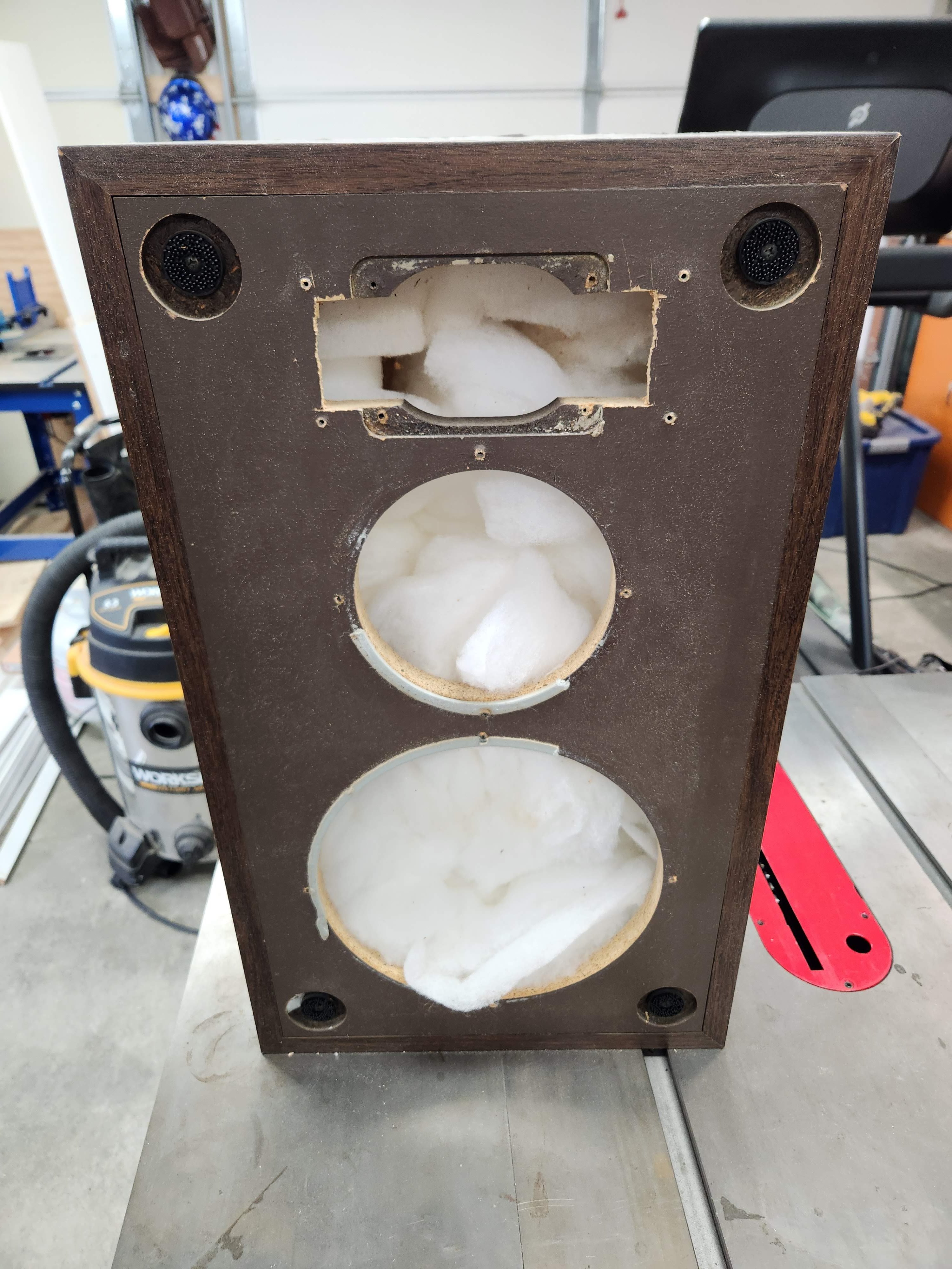
If you'd like to visit the thread above to get a better idea of what we're dealing with, feel free! The abridged version is basically this: a couple of years ago I purchased this set of M7As from FB Marketplace and they had lived hard lives. For starters, the Peerless tweeters had been removed in favor of some horns that someone had put in. In the process of putting these horns in, they must have wanted to give their new jigsaw a workout because they had hacked away some pretty rough openings where the old Peerless units used to live. I got them home and noticed too that 20A fuses had been installed in the backs of the crossovers. What did I get myself into...
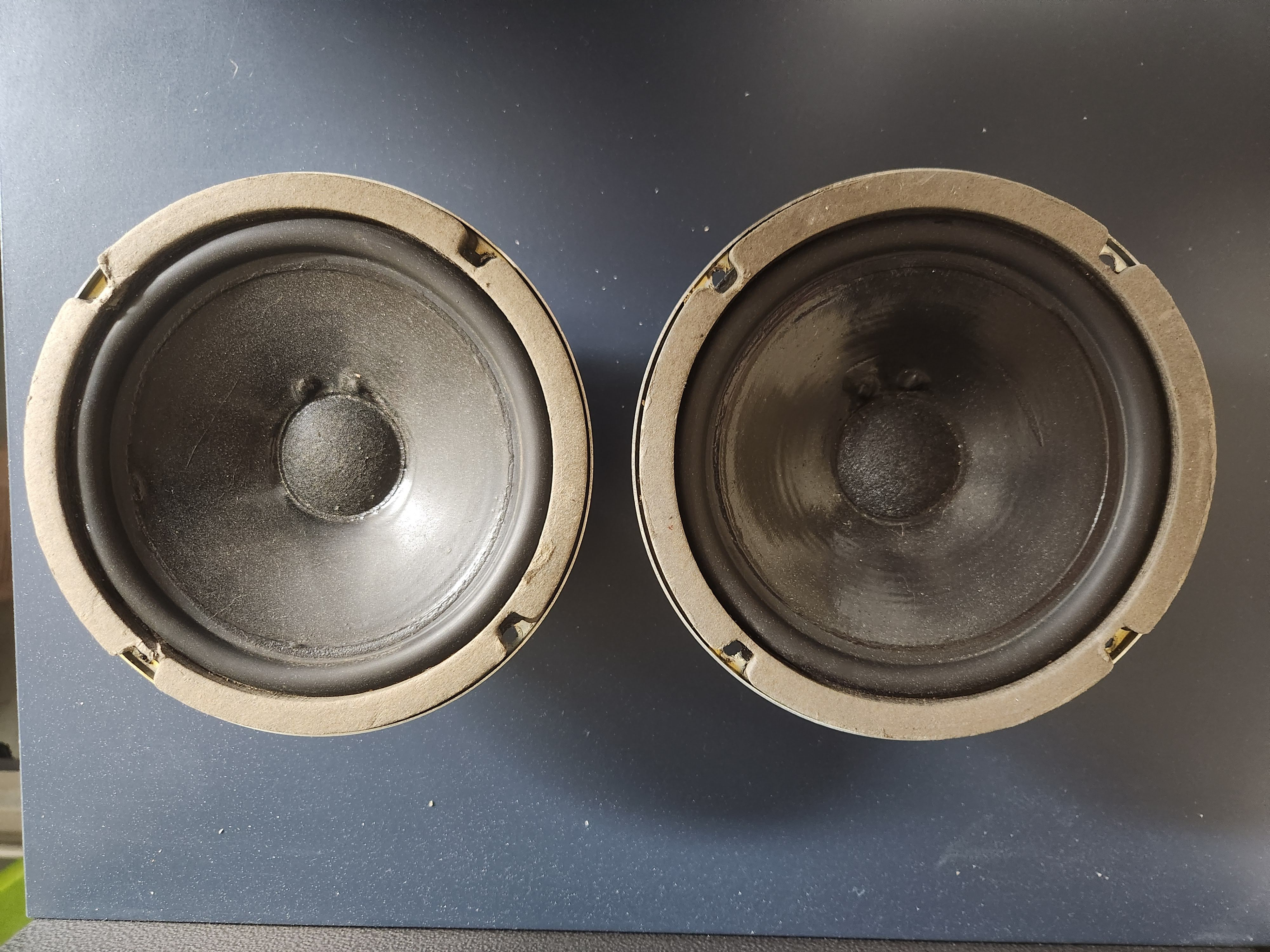
Fast forward to today and I finally have the time to clean them up and give them a new lease on life. Here's what we're working with:
I had decided to attempt to cut out the old baffles and make new ones. I would install them using 1/16" aluminum angle stock to screw into the interior walls of the old cabinets. I have been using threaded hex drive inserts when fastening into the particle board for a more secure fit and they have been working very well so far so I will continue to use them when the time finally comes to mount these new baffles into the original cabinets.
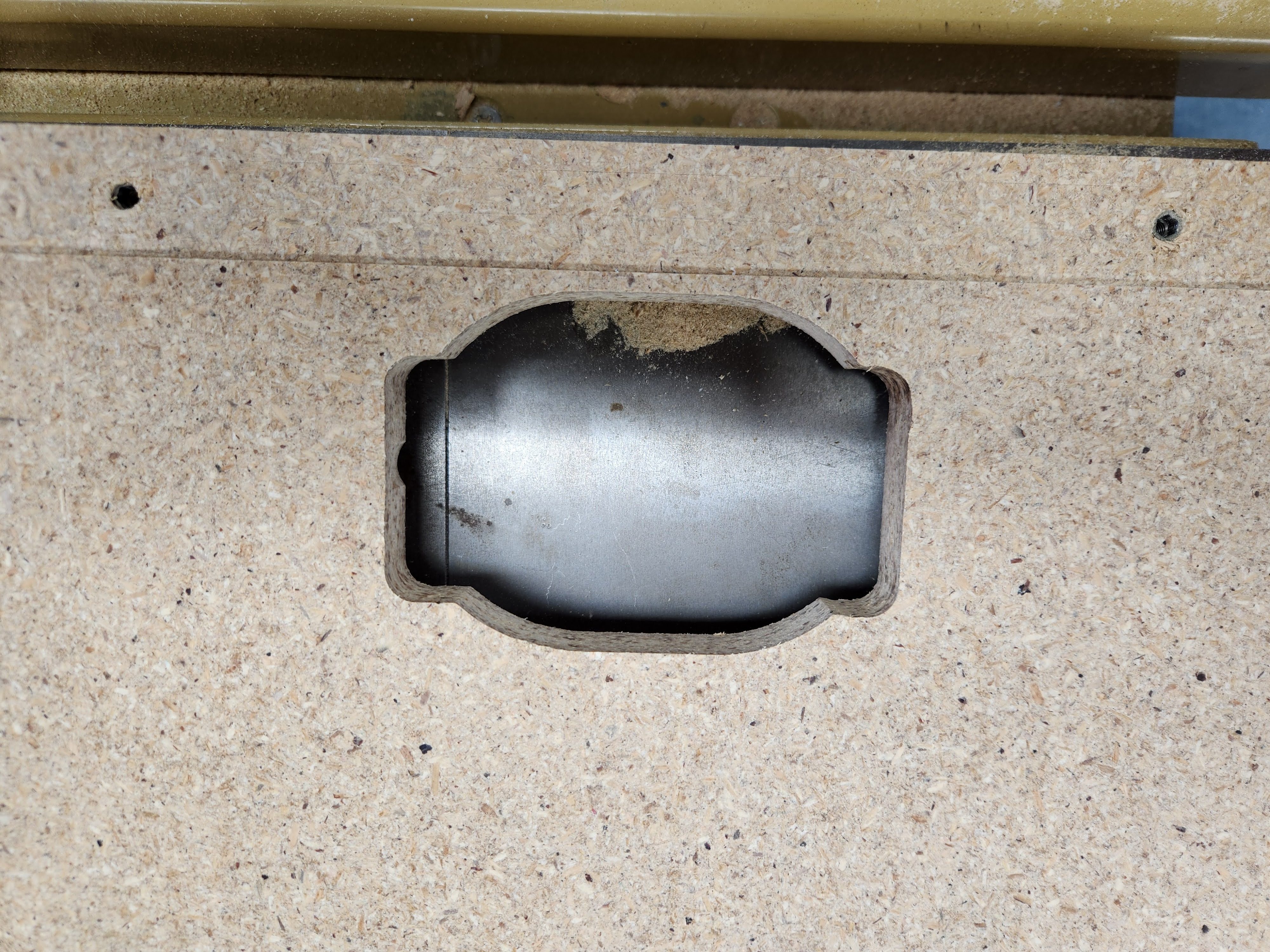
Here is my setup for cutting out the old baffles. I see the irony, doing these on top of my table saw. I know most probably would have opted to use the table saw for this operation but I went this route as I really wanted to be able to see what I was doing and how far I was going. At least this way, the cabinets are right side up instead of upside down like they would be had I ripped them on the table saw. I would say for the most part this method worked well. I used a clamp as my fence and cut the baffle out with my compact circular saw. I finished the corners off with my oscillating tool and overall I'd say it worked out pretty well.
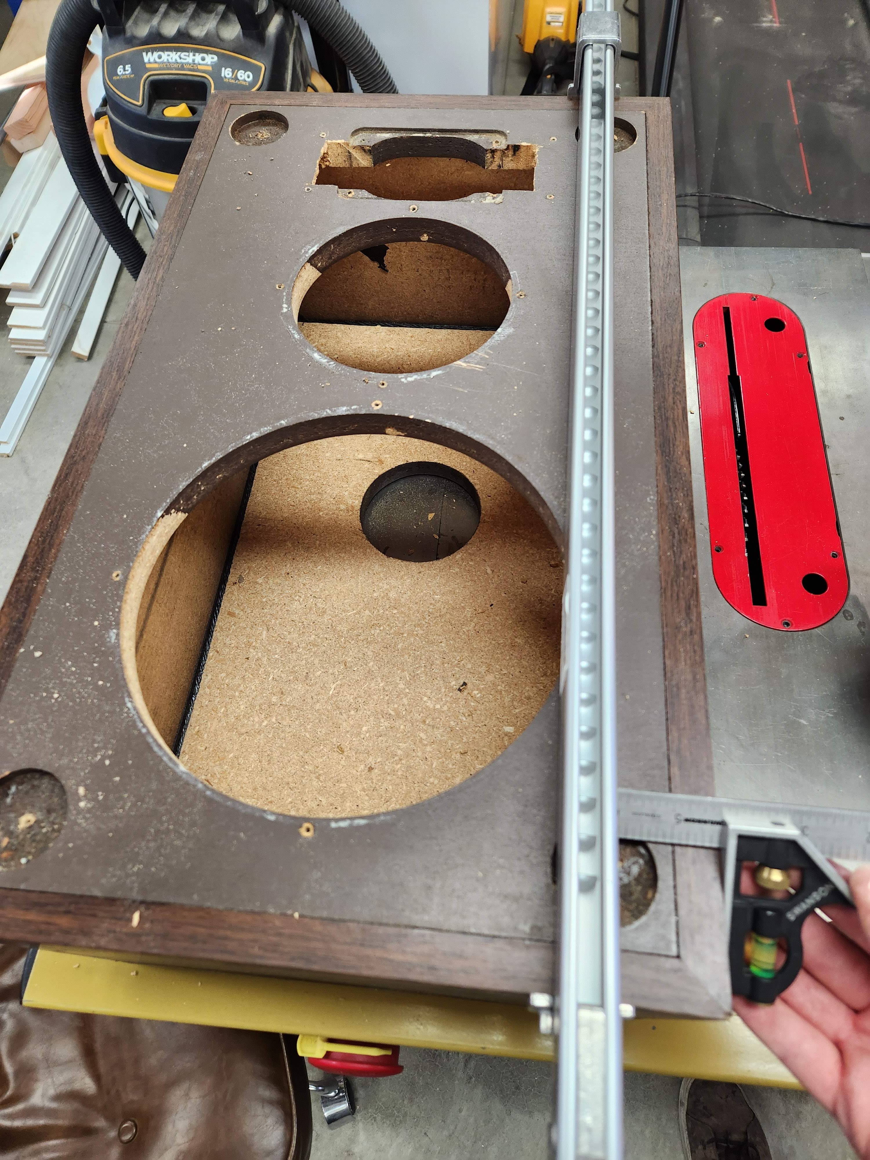
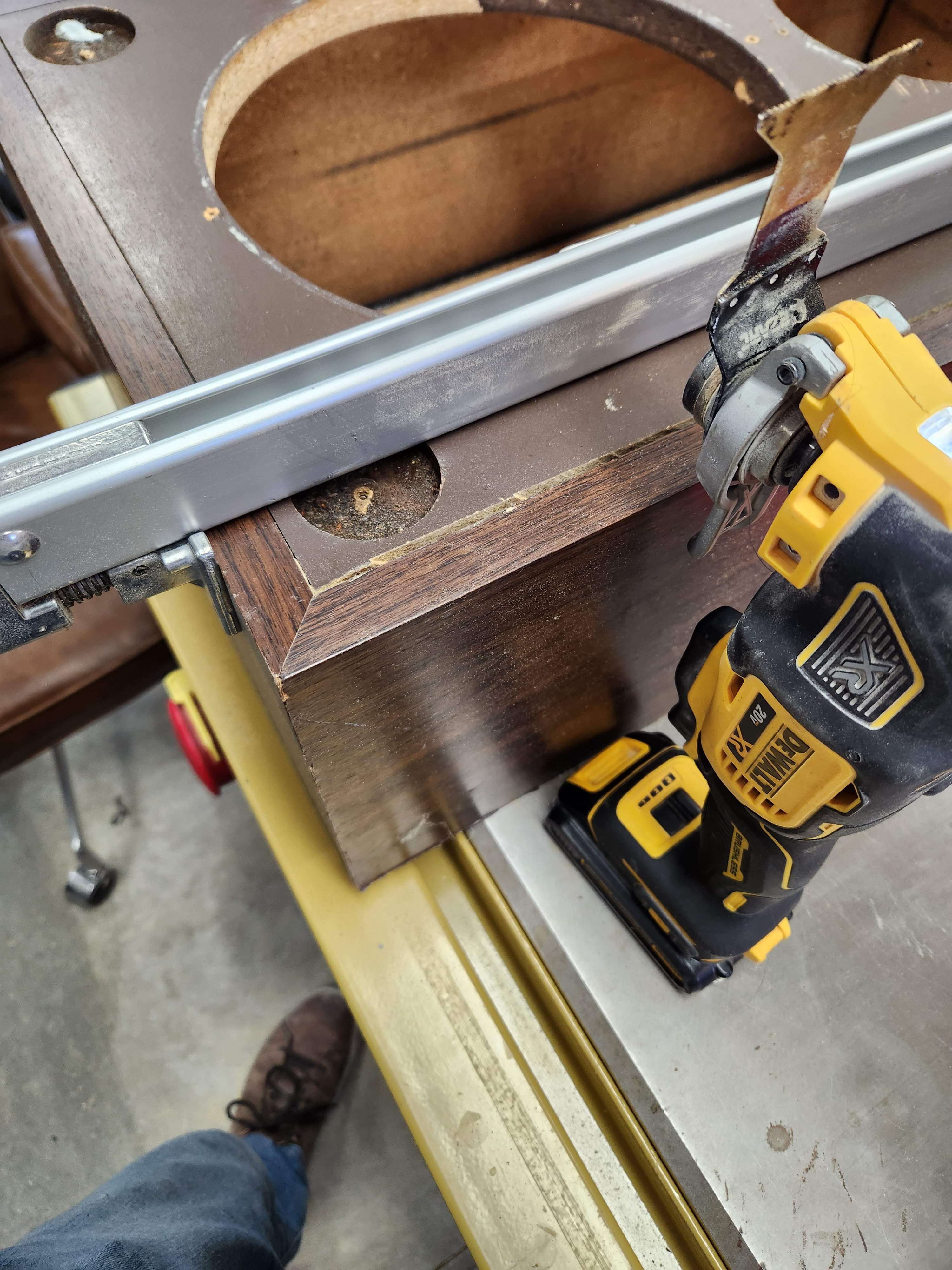
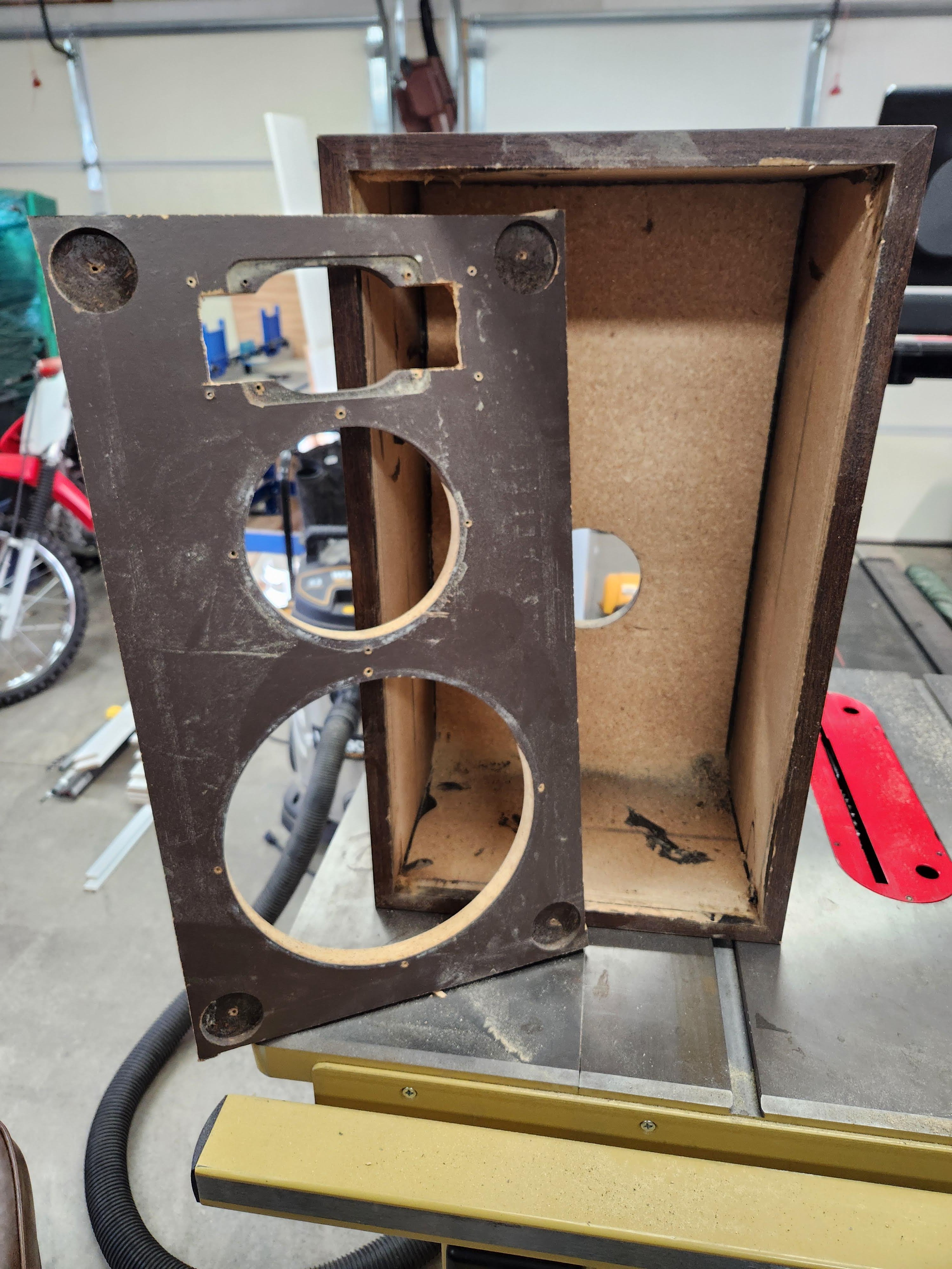
As you can see, there are a couple of spots where I had allowed the saw blade to deviate a bit, cutting into the front edges of the cabinet but nothing severe that couldn't be filled and veneered over. I don't think that's in the cards quite at this time, but at least I have the option to do this at a later time if I choose to take this restoration all the way.
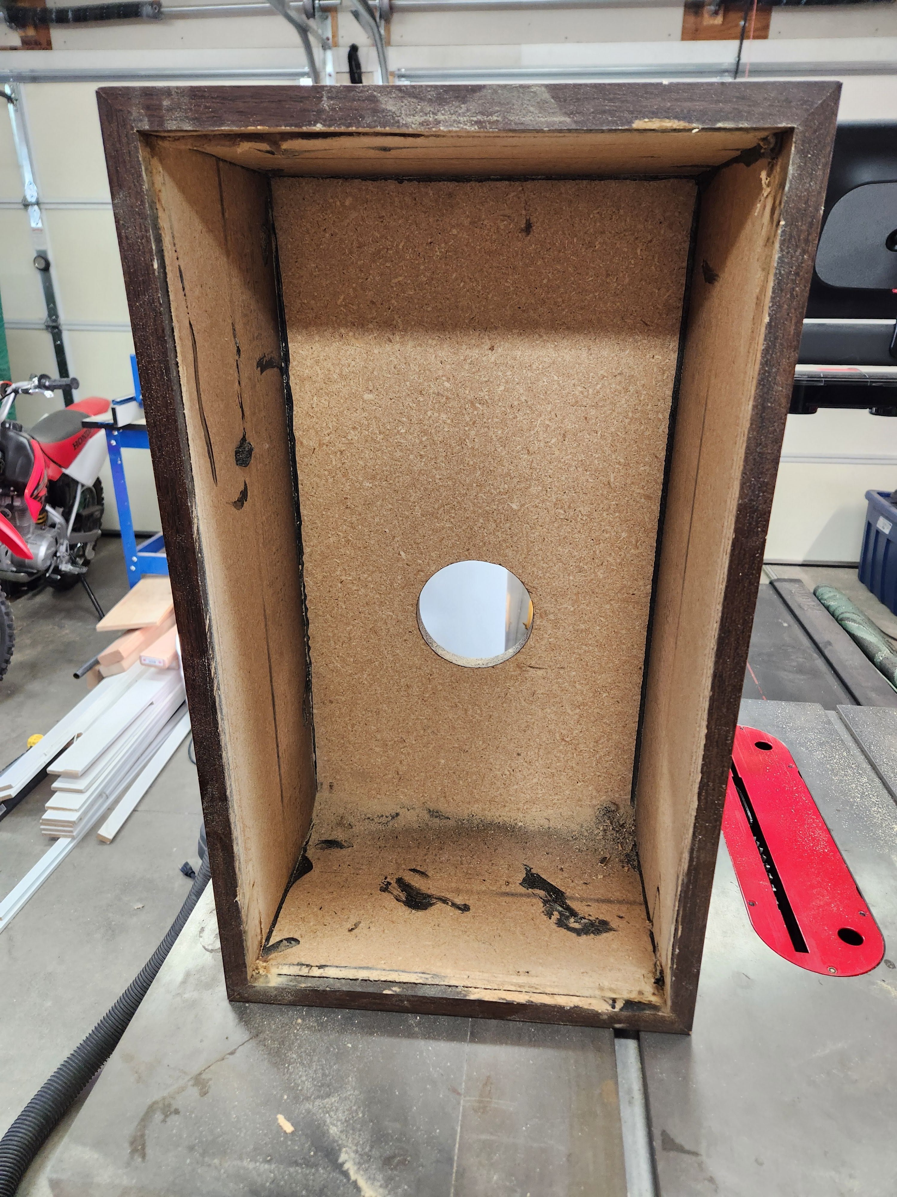
After I got the baffle cut out, I smoothed out the interior walls of the cabinet with an orbital sander, then I began working on the new baffles.
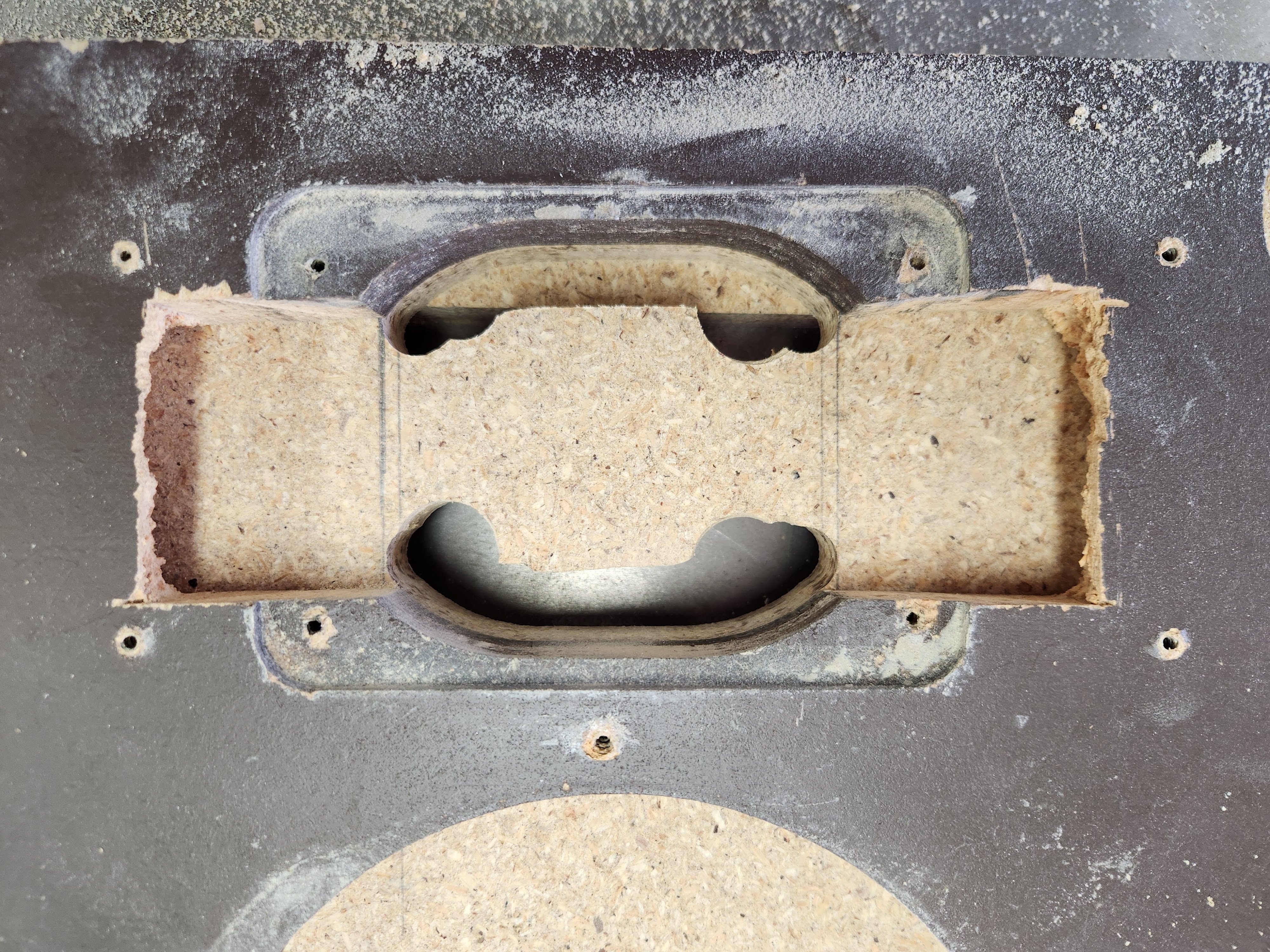
Time to make the new baffle. My first attempt at this had failed. I started with routing the opening for the tweeter as this operation had the highest likelihood of me **** it up. If I did screw it up, better to have to start over with less work to redo than had I done this operation last. In my first attempt, I used as much of the original baffle as a template as I could. Well, this ended up with less than satisfactory results. I realized that from the factory, the geometry for the tweeter cutout wasn't exactly perfect. I'm sure they dialed this in later in the game but this is a very early iteration of the Monitor 7 that we are working with here so its understandable and frankly, kind of funny. Makes me picture a 20 something year old back in the 70s hand routing this thing in a garage or something. That's pretty cool to me actually, but, I saw some room for improvement here so I took it! The curve at the top of the tweeter opening and the bottom of the opening are skewed:
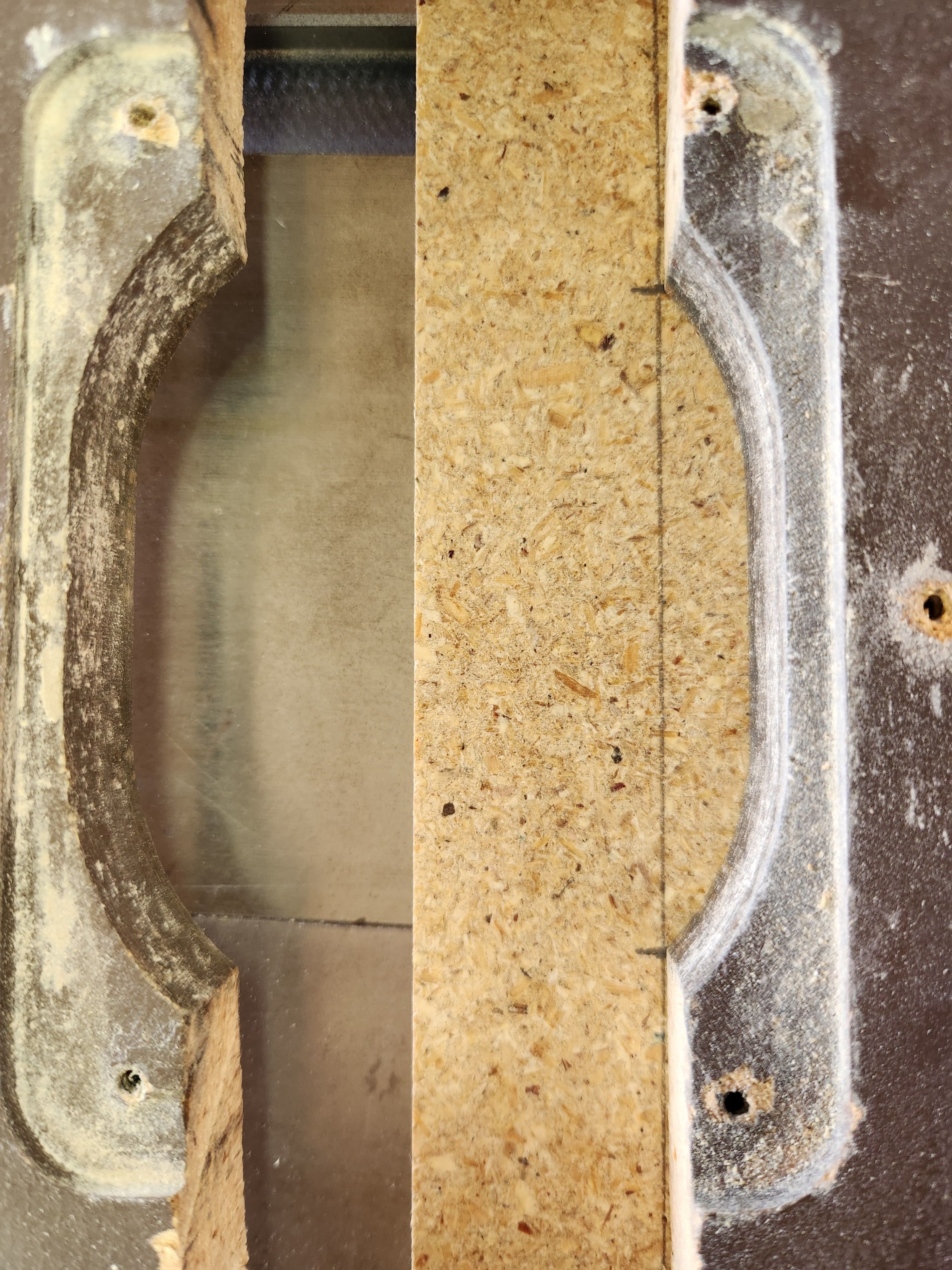
It almost looks like to me, a combination of them not being quite the same size and not being perfectly aligned with one another. I hadn't noticed this right away but it had become evident in my newly cut baffle when I was looking at it closely. Also, I screwed up in the process of routing and forgot to adjust the depth of my bit, thus cutting into my particle board fence and into the side of my cutout.
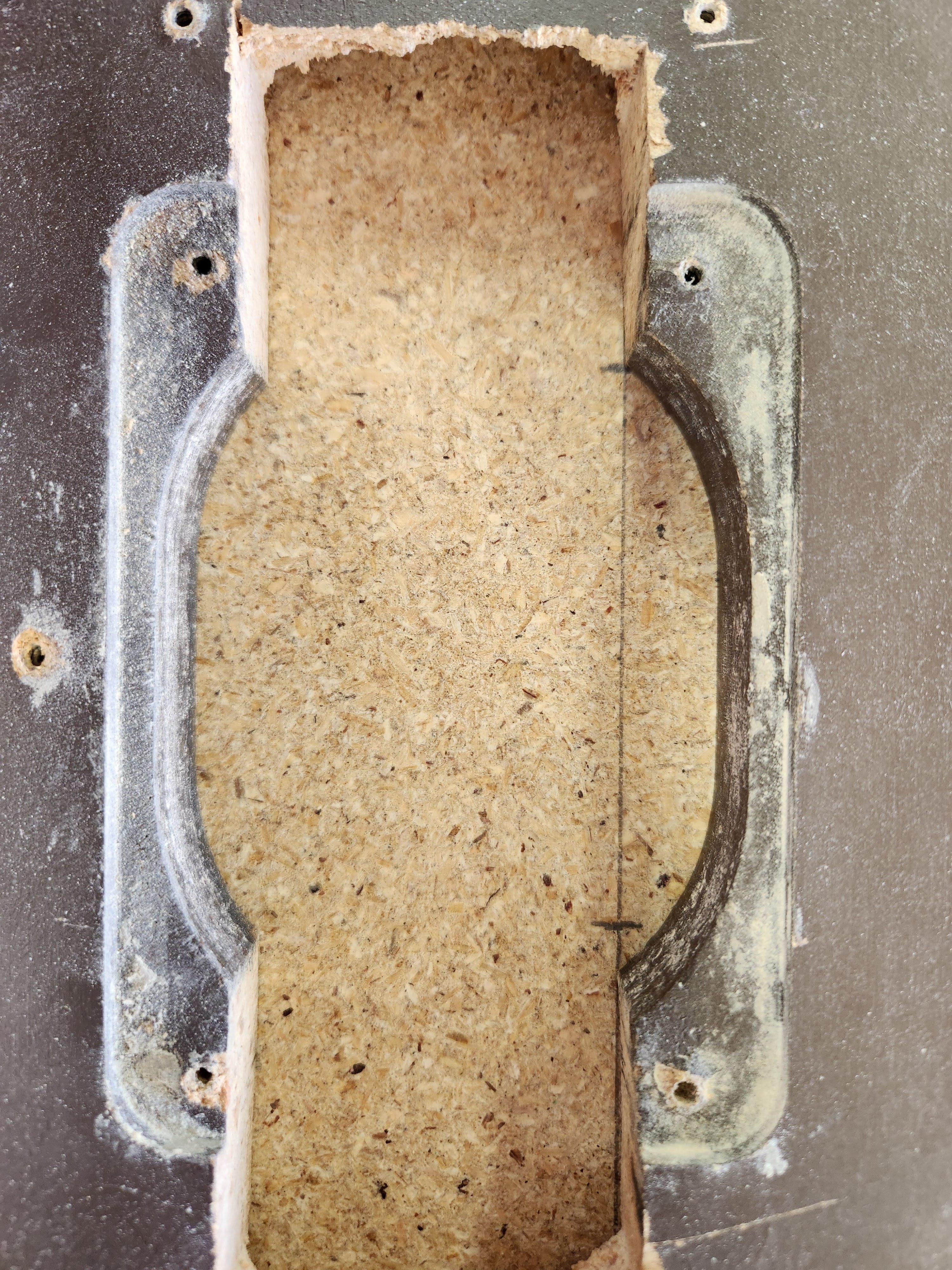
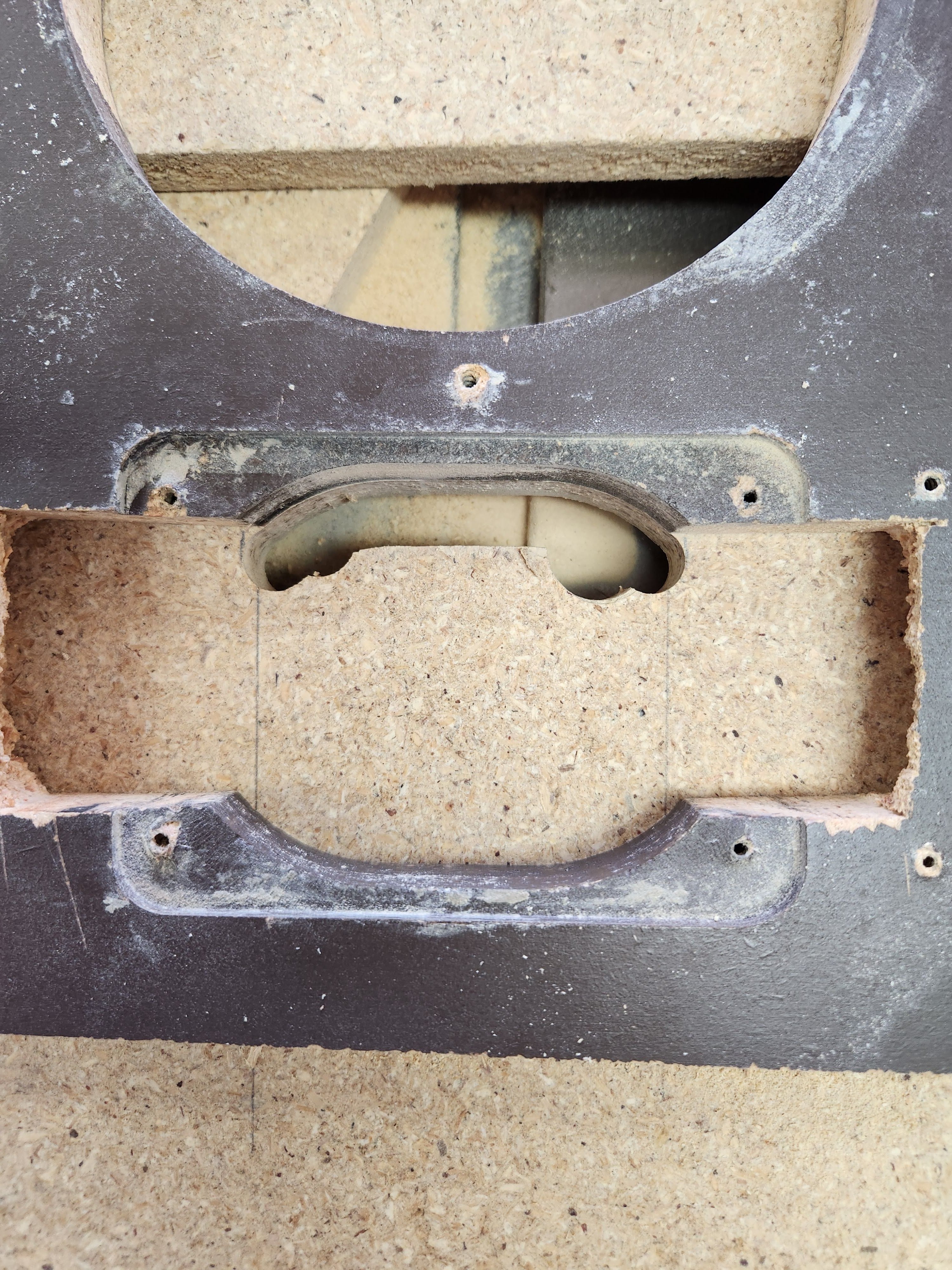
Here's what my first attempt ended up looking like:
I was not satisfied with this and thankfully I had enough particle board on hand to absorb this mistake and still have enough to make 2 new baffles. I think I can count on one hand how many times I have been lucky enough to avoid another trip to the hardware store like that!
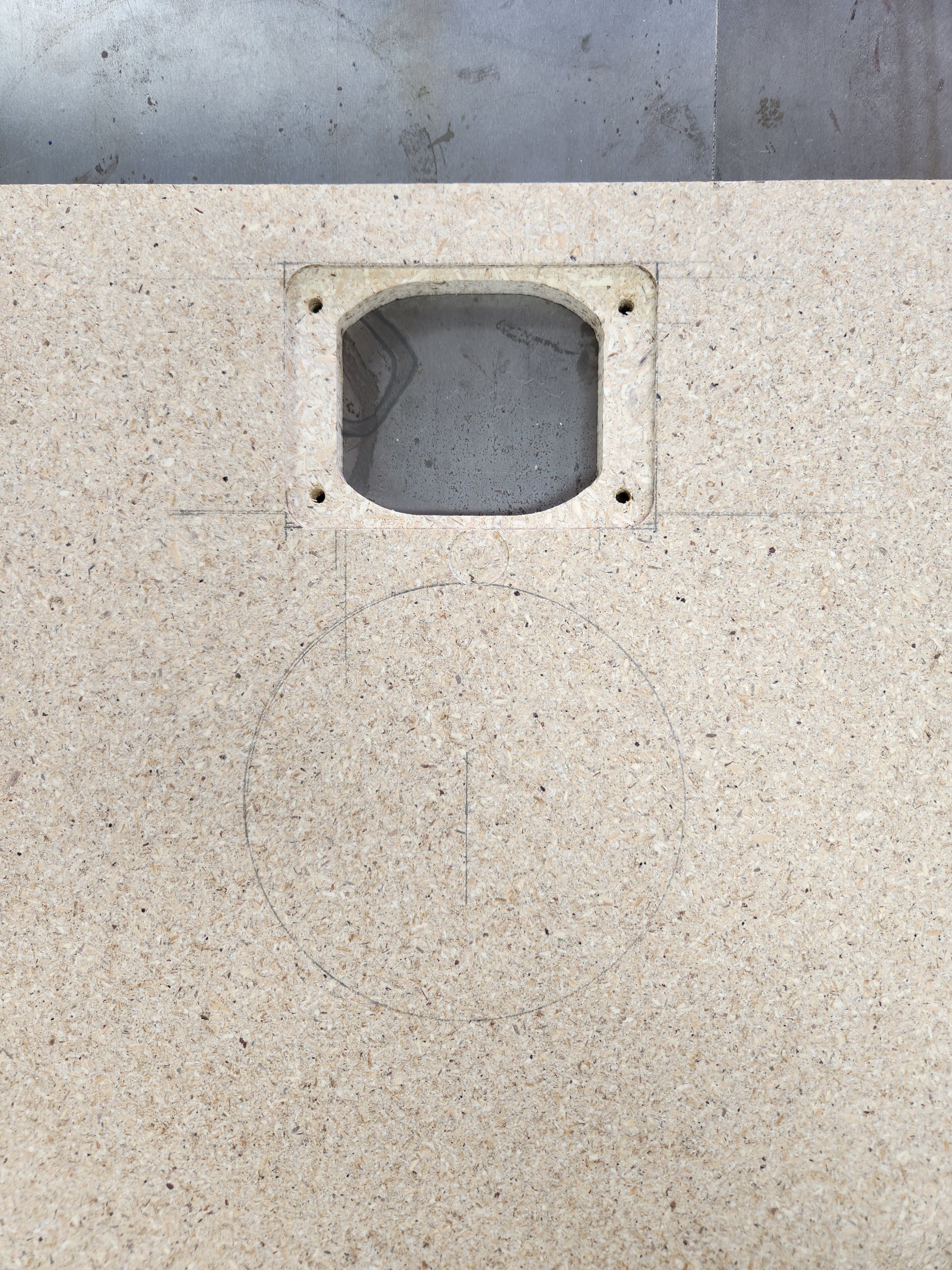
For my second attempt, I decided to use only the top curve of the tweeter cutout on the original baffle as a template, and use that template to cut both the top and the bottom curves of the cutout on the new baffle. This provided better results in the end and proved to be much easier overall.
After this was done, I connected the two curves, top and bottom, and cut out my counterbored rectangle. I got very lucky as I happened to have the proper 3/4" diameter cutting tool on hand to achieve the desired 3/8 radius at each corner of the counterbore. Basically I used a tool similar to a 3/4" flat end mill to achieve the rounded rectangle around the thru cutout. Here is the finished product, much better than my first attempt!
I went ahead and got my holes drilled for the Peerless tweets. I used one of the tweeters as a template for where to put the holes. Alignment looks very good! If you look closely you can see another mistake I made, just below the tweeter cutout. Screwed up when routing out the rounded rectangle, but I decided this wasn't enough to justify starting over. I will eventually fill this in with some Bondo before painting.
Time really does fly. Well in that time, a lot happened that put these speakers on the back burner for me for quite some time, until now...
This is my first pair of Monitor 7 speakers. I am very excited to hear them for the first time. Before I get too into detail here I will say that these will be on garage duty, so unfortunately a full cosmetic restoration is not quite in order for these at this time. Also it's worth noting that due to space constraints, I will not be putting these on their proper stands (they did not come with stands when I purchased them anyways). Instead, they will live on some shelves I made and mounted to opposing ends of one of the walls in my garage. But don't worry, there's still plenty to unpack here.
If you'd like to visit the thread above to get a better idea of what we're dealing with, feel free! The abridged version is basically this: a couple of years ago I purchased this set of M7As from FB Marketplace and they had lived hard lives. For starters, the Peerless tweeters had been removed in favor of some horns that someone had put in. In the process of putting these horns in, they must have wanted to give their new jigsaw a workout because they had hacked away some pretty rough openings where the old Peerless units used to live. I got them home and noticed too that 20A fuses had been installed in the backs of the crossovers. What did I get myself into...
Fast forward to today and I finally have the time to clean them up and give them a new lease on life. Here's what we're working with:
I had decided to attempt to cut out the old baffles and make new ones. I would install them using 1/16" aluminum angle stock to screw into the interior walls of the old cabinets. I have been using threaded hex drive inserts when fastening into the particle board for a more secure fit and they have been working very well so far so I will continue to use them when the time finally comes to mount these new baffles into the original cabinets.
Here is my setup for cutting out the old baffles. I see the irony, doing these on top of my table saw. I know most probably would have opted to use the table saw for this operation but I went this route as I really wanted to be able to see what I was doing and how far I was going. At least this way, the cabinets are right side up instead of upside down like they would be had I ripped them on the table saw. I would say for the most part this method worked well. I used a clamp as my fence and cut the baffle out with my compact circular saw. I finished the corners off with my oscillating tool and overall I'd say it worked out pretty well.
As you can see, there are a couple of spots where I had allowed the saw blade to deviate a bit, cutting into the front edges of the cabinet but nothing severe that couldn't be filled and veneered over. I don't think that's in the cards quite at this time, but at least I have the option to do this at a later time if I choose to take this restoration all the way.
After I got the baffle cut out, I smoothed out the interior walls of the cabinet with an orbital sander, then I began working on the new baffles.
Time to make the new baffle. My first attempt at this had failed. I started with routing the opening for the tweeter as this operation had the highest likelihood of me **** it up. If I did screw it up, better to have to start over with less work to redo than had I done this operation last. In my first attempt, I used as much of the original baffle as a template as I could. Well, this ended up with less than satisfactory results. I realized that from the factory, the geometry for the tweeter cutout wasn't exactly perfect. I'm sure they dialed this in later in the game but this is a very early iteration of the Monitor 7 that we are working with here so its understandable and frankly, kind of funny. Makes me picture a 20 something year old back in the 70s hand routing this thing in a garage or something. That's pretty cool to me actually, but, I saw some room for improvement here so I took it! The curve at the top of the tweeter opening and the bottom of the opening are skewed:
It almost looks like to me, a combination of them not being quite the same size and not being perfectly aligned with one another. I hadn't noticed this right away but it had become evident in my newly cut baffle when I was looking at it closely. Also, I screwed up in the process of routing and forgot to adjust the depth of my bit, thus cutting into my particle board fence and into the side of my cutout.
Here's what my first attempt ended up looking like:
I was not satisfied with this and thankfully I had enough particle board on hand to absorb this mistake and still have enough to make 2 new baffles. I think I can count on one hand how many times I have been lucky enough to avoid another trip to the hardware store like that!
For my second attempt, I decided to use only the top curve of the tweeter cutout on the original baffle as a template, and use that template to cut both the top and the bottom curves of the cutout on the new baffle. This provided better results in the end and proved to be much easier overall.
After this was done, I connected the two curves, top and bottom, and cut out my counterbored rectangle. I got very lucky as I happened to have the proper 3/4" diameter cutting tool on hand to achieve the desired 3/8 radius at each corner of the counterbore. Basically I used a tool similar to a 3/4" flat end mill to achieve the rounded rectangle around the thru cutout. Here is the finished product, much better than my first attempt!
I went ahead and got my holes drilled for the Peerless tweets. I used one of the tweeters as a template for where to put the holes. Alignment looks very good! If you look closely you can see another mistake I made, just below the tweeter cutout. Screwed up when routing out the rounded rectangle, but I decided this wasn't enough to justify starting over. I will eventually fill this in with some Bondo before painting.
Comments
-
After this was done, a sigh of relief... Only to realize I better be on my A-game from here on out because I did not want to have to do all of that work again if I happen to screw up further down the road. Thankfully it was pretty much down hill after this. I still had to cut two thru circles for the driver and passive radiator, and I had to cut the four blind circles for the Velcro pads used for attaching the grilles. No counterbored circles on 7As.
I have a circle cutting jig for my router and have used it successfully in the past, but it's tedious to setup and I opted to continue instead to use my old baffle as a template for cutting the driver and passive radiator holes. Thankfully the previous owner(s) had left these holes in tact at least! So off I went on getting those cut. I took the time to get each hole perfectly positioned along the new baffle by measuring and drawing a centerline along the middle of the new baffle and I used a compass to draw out the circles where they should be. This way I didn't need to try and line up the old and new baffles. This would have been unsuccessful as the edges of the old baffle were pretty chewed up and trying to align the two for hole positioning would have been difficult and less accurate. So this way I could simply line up the holes on the old baffle with the drawn out circles on the new baffle and clamp everything down with perfect alignment.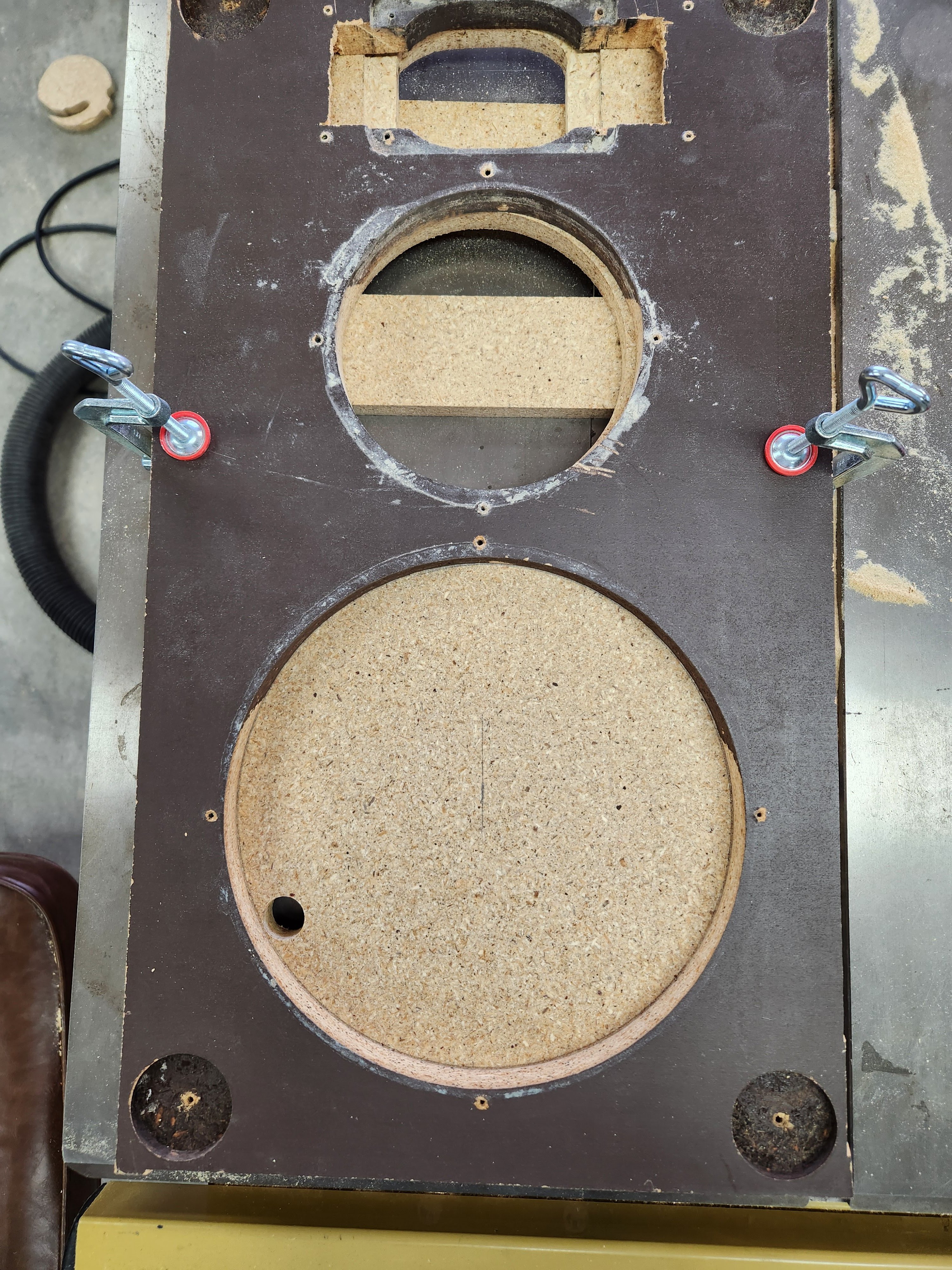
I am very happy with how this turned out!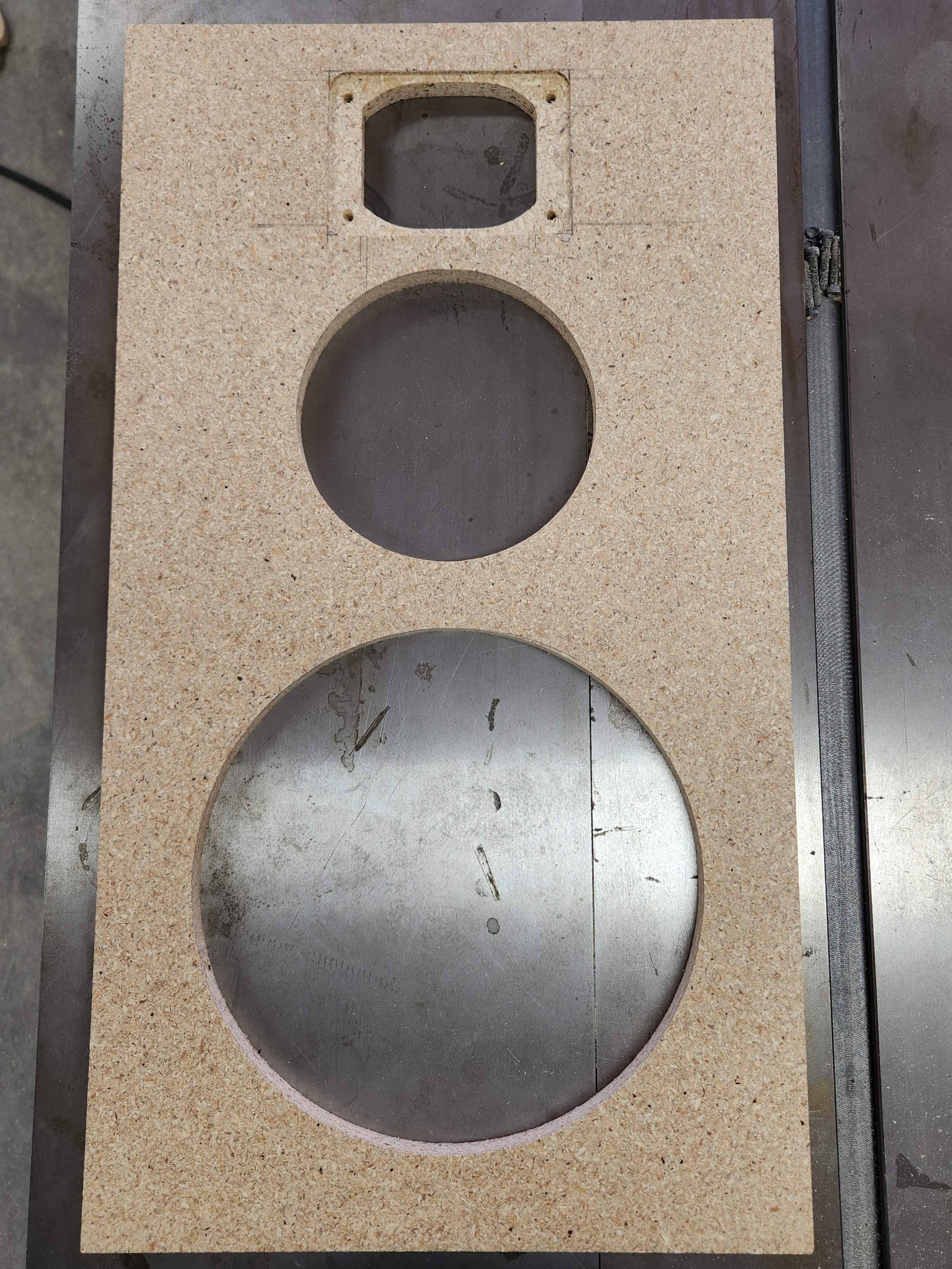
After this step I decided to go ahead and cut the blind holes at each corner of the baffle. My initial plan was to simply cut these with a Forstner bit. I measured the holes and they came in at 1-3/4". I figured this would be no problem as I have a decent size set of Forstner bits on hand going up to 2". I should have 1-3/4" I thought, no problem. Wrong! My set jumps from 1-5/8" to 2". Really? I get a 1-5/8" bit but not a 1-3/4"? In what world does a 1-5/8" bit come standard where a 1-3/4" bit is not? Ugh. I thought about going to the hardware store but I was pretty locked in at the time. Well, I'm sure you guys know how that goes. Me personally I will spend two hours doing something another way if it saves me a 1 hour trip to the hardware store lol, so I thought about and decided to continue to use as much of my original baffle as I could.
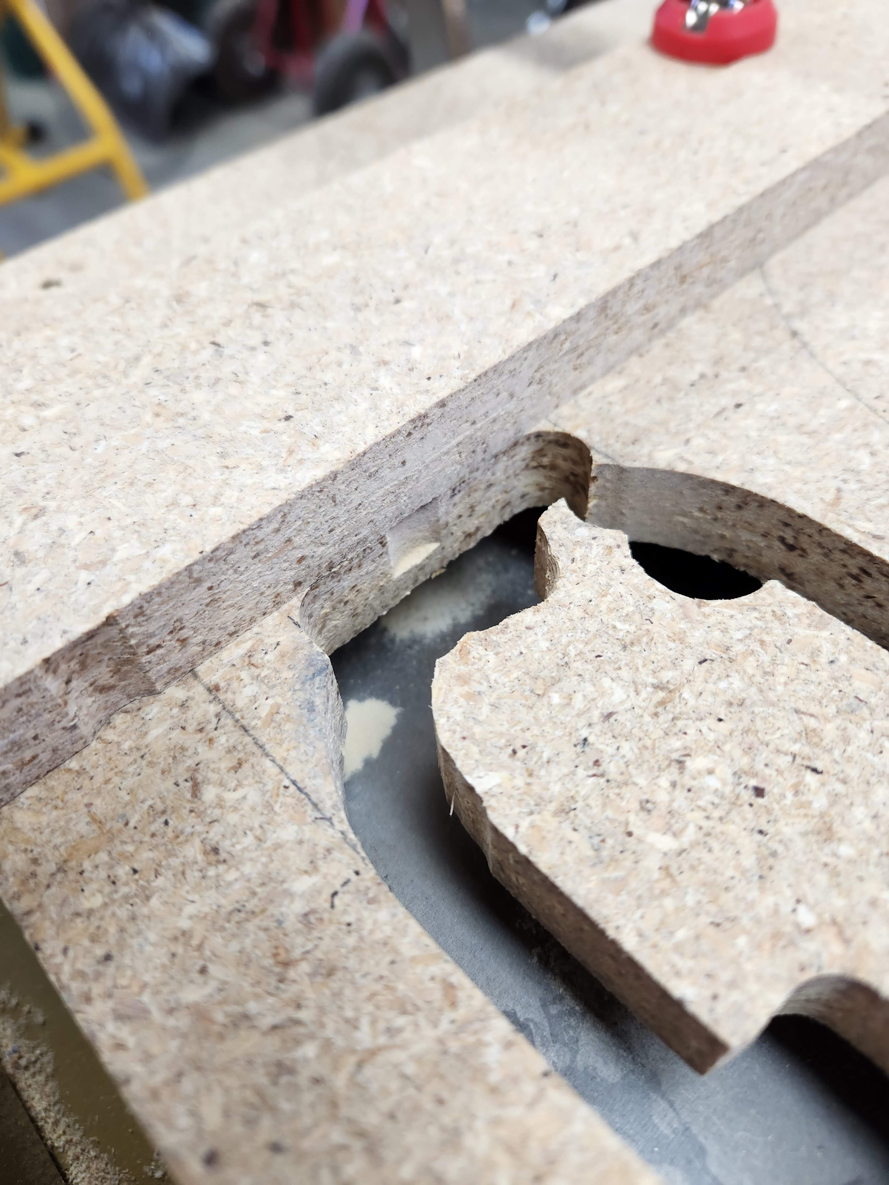
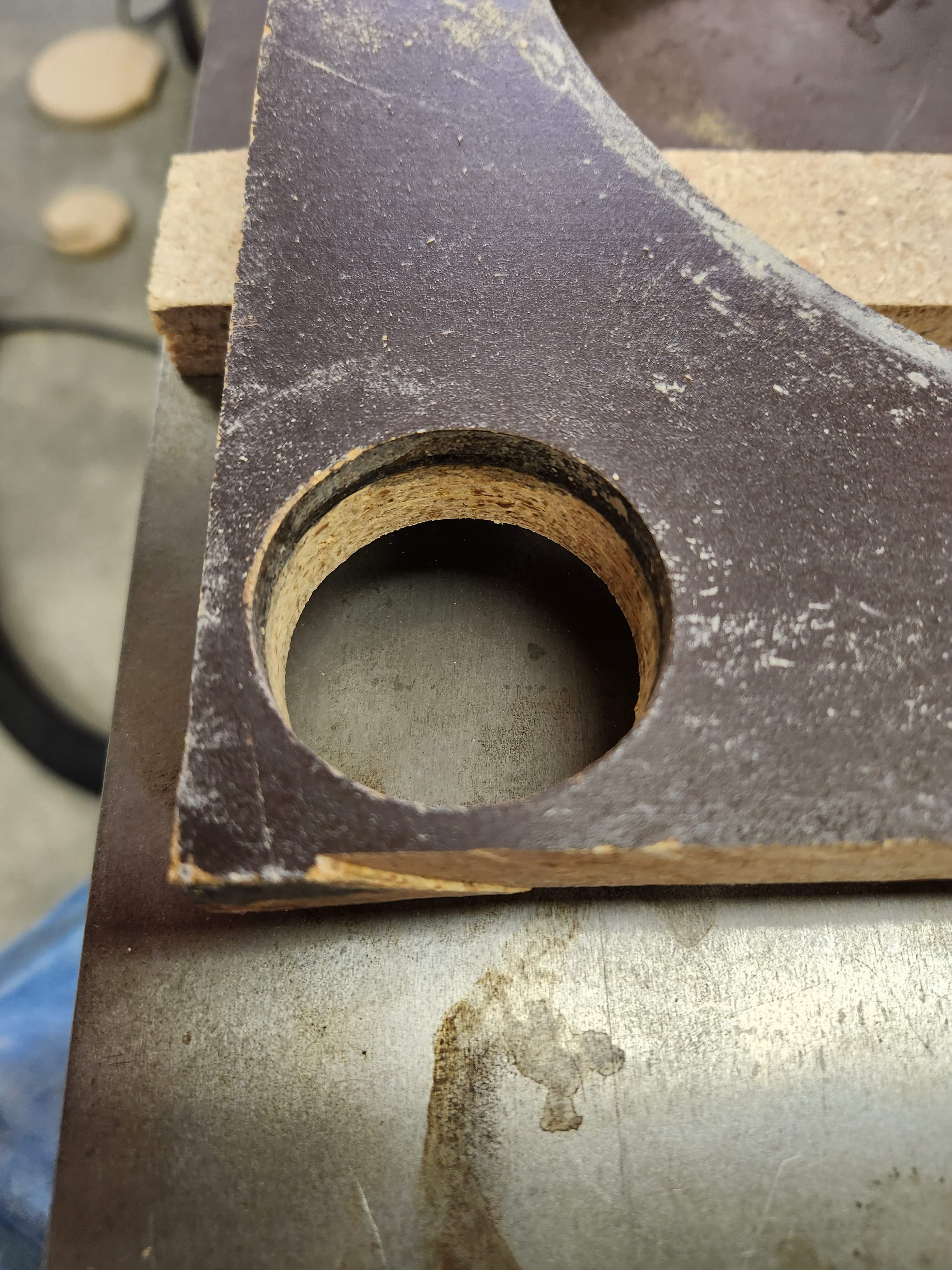
So I took one of the blind holes on the old baffle and I made it a thru hole with my router. (PS - notice that I have been using this flush trim bit for almost everything router-related so far. If you don't have one of these and you have been on the fence about it, get one! They are one of the most valuable cutting tools for a router that you can buy. I would buy one with the bearing above the cutting teeth, and one with the bearing below the cutting teeth. They are both very useful in different applications).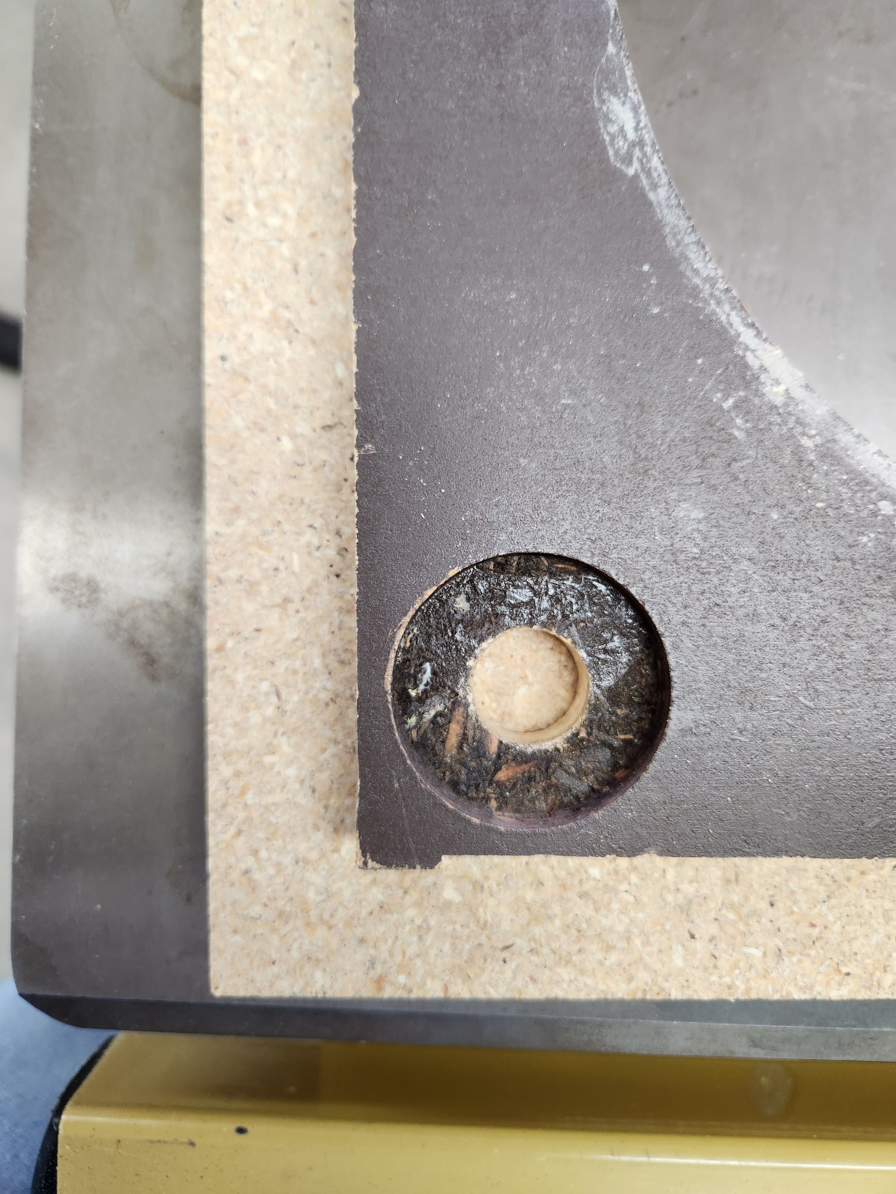
After I made the thru hole, I thought I was ready to roll with my newly made ghetto template but I ran into a problem. The template was too thin for my router bit to achieve the desired depth of the blind holes on the new baffle.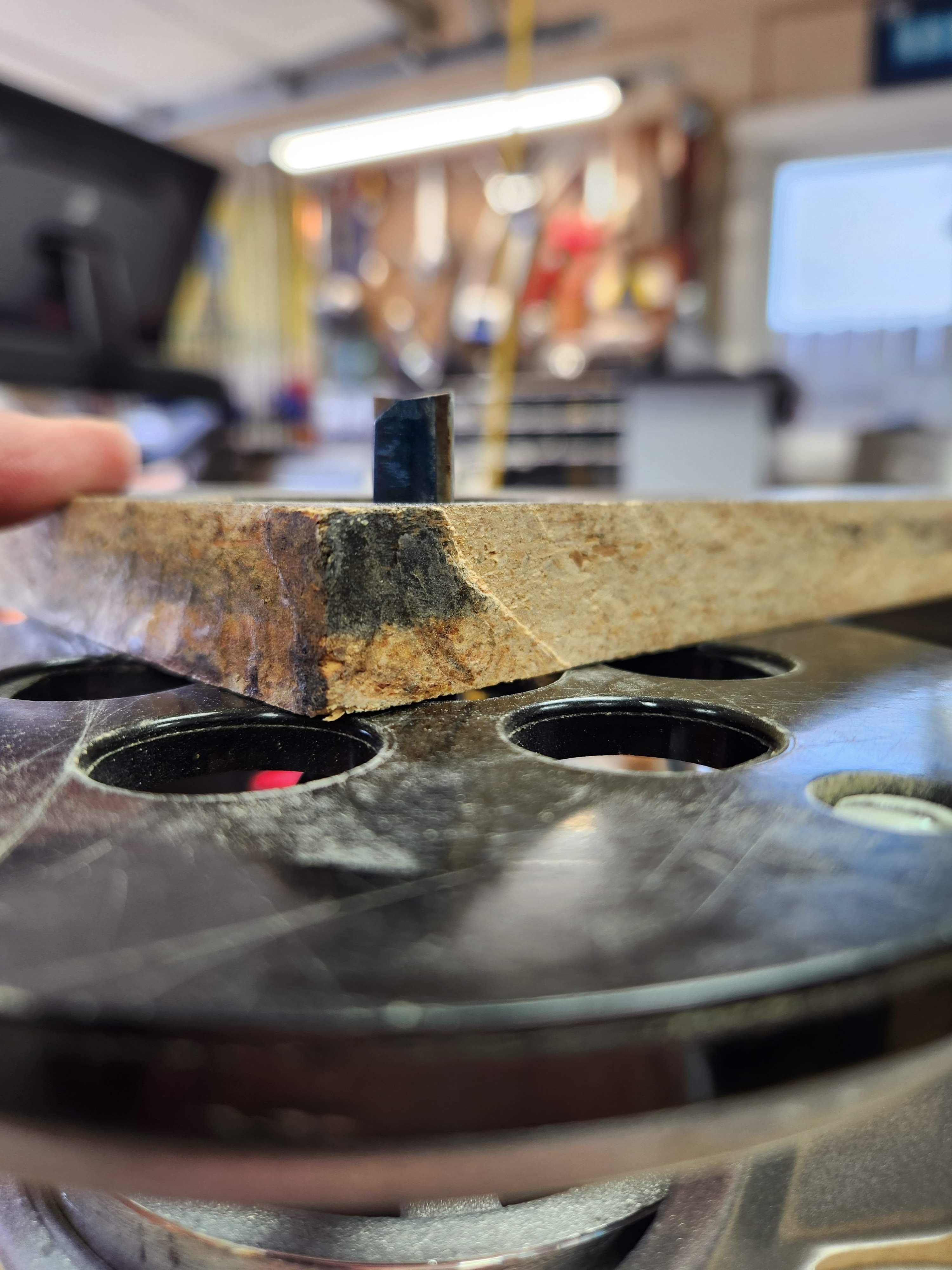
There's always something... What I ended up doing is doubling down on the ghetto factor here and making another template from the opposing corner of my old baffle. So I made another template and joined the two together with some screws after getting the holes lined up perfectly. I cut the corners at an angle on my miter saw so that I could have plenty of real estate to clamp this double stacked monstrosity of a template onto the new baffle. I was naturally a little reluctant to proceed as I had invested a fair amount of work by this time into the new baffle so far, but I knew I had to keep going. While working on this, I had my Signa S4 soundbar playing from my phone and it does an okay job but I really want sound coming at me from more than one corner of the garage and the thought of finally having proper stereo sound in the garage was just the motivation I needed to keep going!
Here is the double-stack hole template, in all of its horrific glory: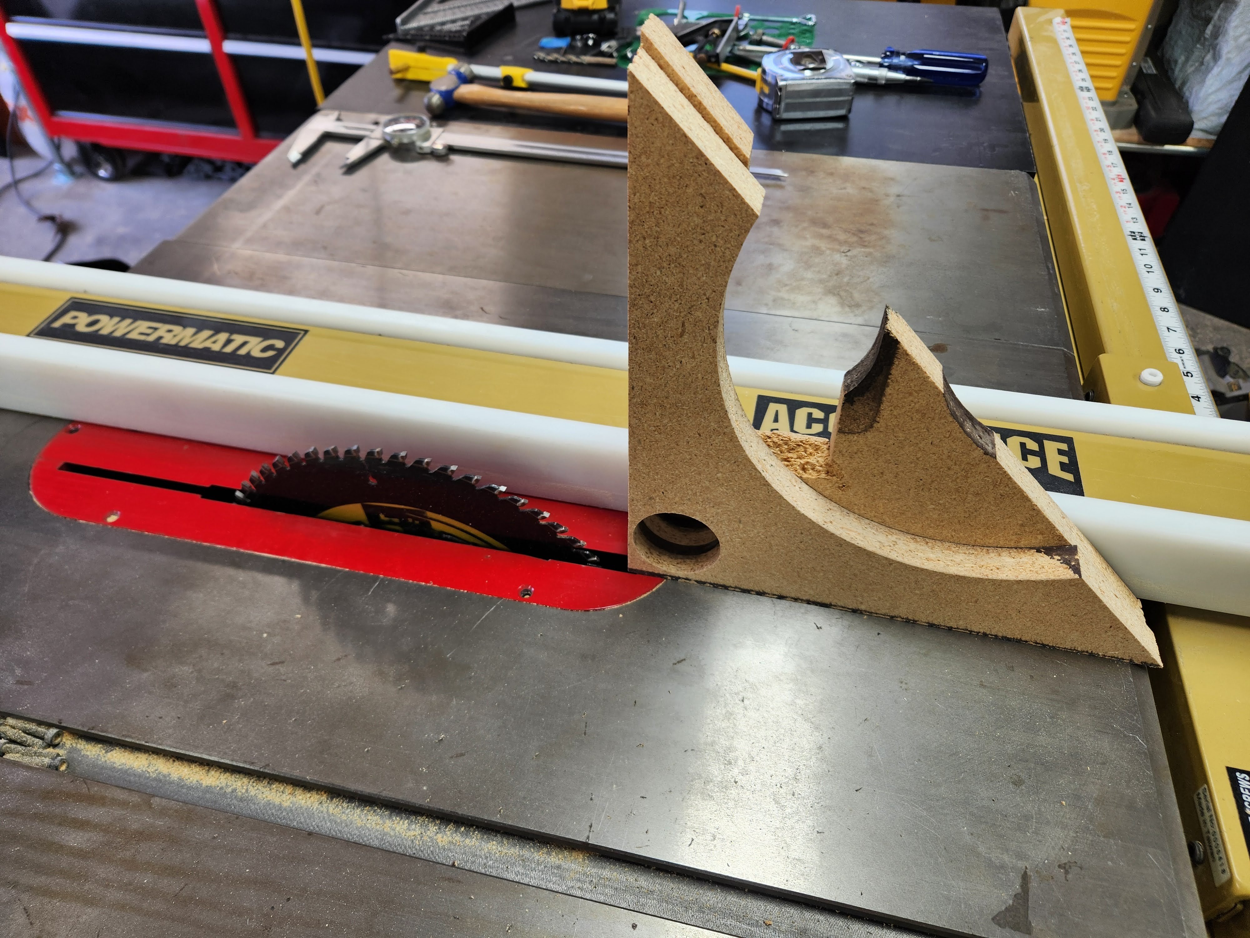
Funny enough, after joining the two pieces, the template was now too thick. Can't make this stuff up lol. So I cut it down to a thickness that would work on the table saw. Sketchy, I know... But after all is said and done, it did indeed work.
Before cutting the blind holes, I needed to drill my center holes for the screw that secures the Velcro tabs to the baffle. Had I been able to use a Forstner bit, this would have been very easy as a pilot hole would have been made for me by the bit. All I would have to do is finish it off for the proper diameter and depth. What I had to do instead was find the center of the circle another way. I drew the 1-3/4" circle with one of those plastic circle sheet guides that kids use in school. Man those really are useful to have around when you need them. To find the center, I drew a 45 degree line from the corner and used the same sheet guide to draw a 7/8" arc, the radius of 1-3/4". There are much cooler and craftier ways to find the center of the circle but this worked perfectly for me.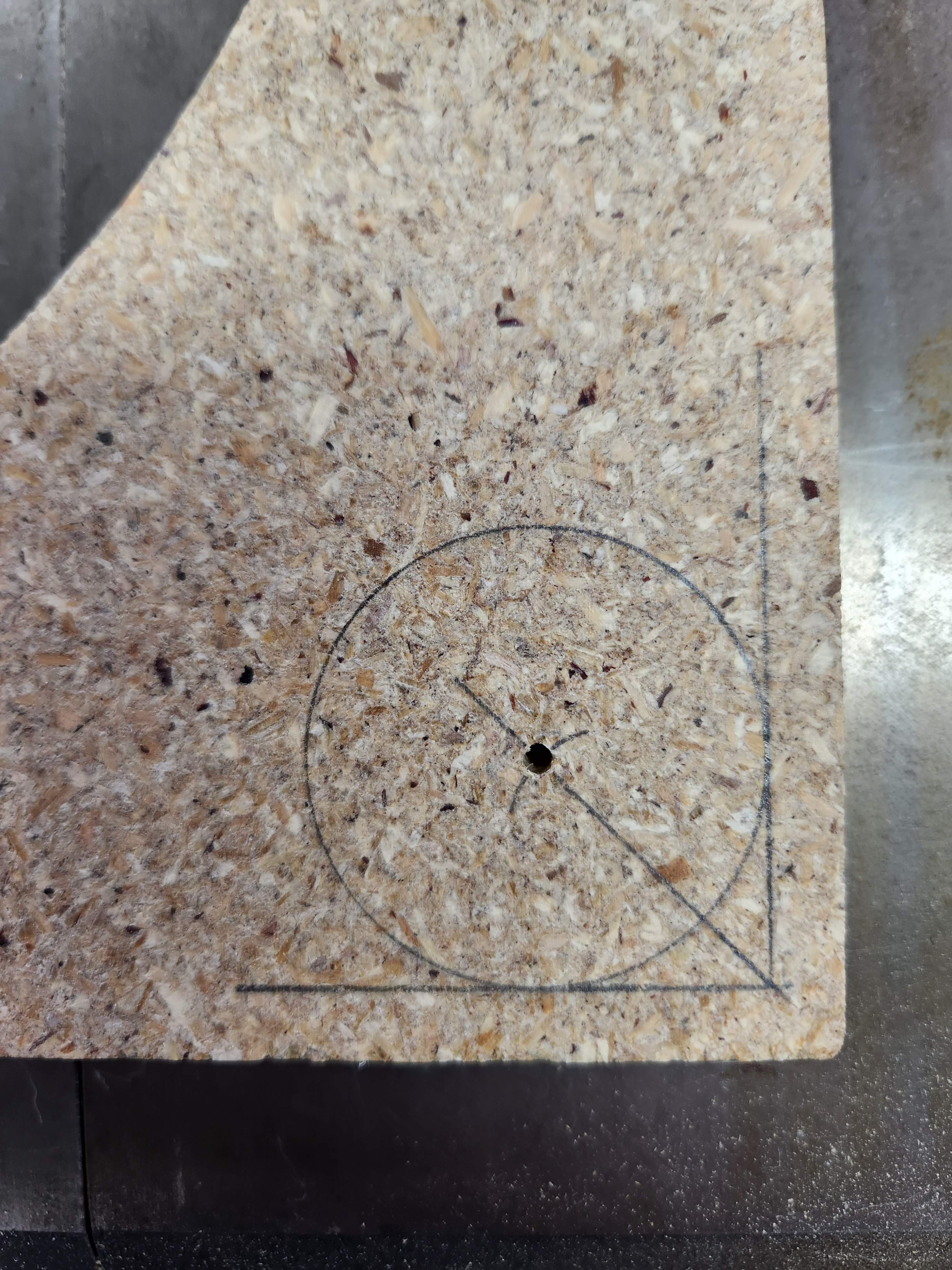
Here is what I have after this: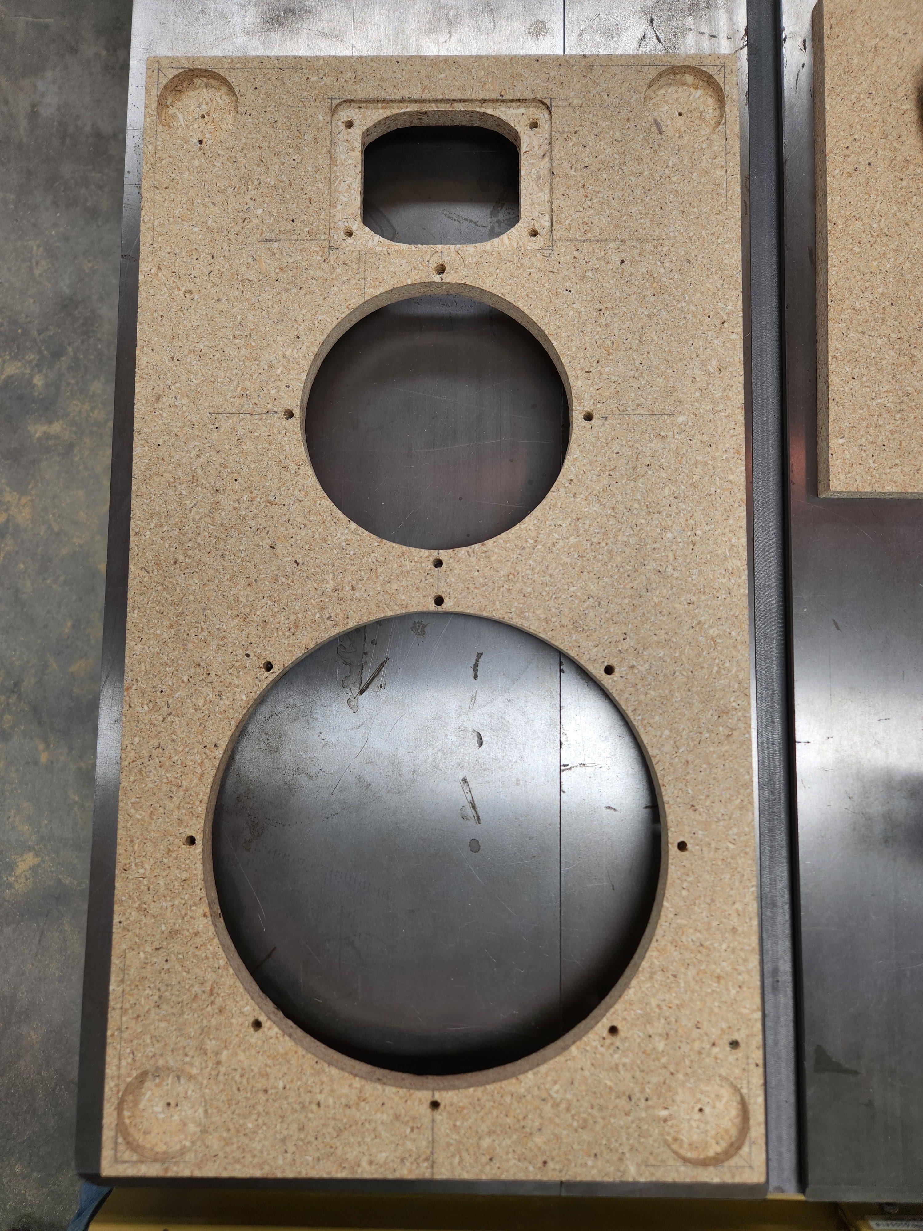
Once I had the front of the baffle done, I turned my attention to the back. I cut a 1/16" deep rabbet around the entire perimeter of the baffle at the rear. The aluminum channel that I will be using to fasten the new baffle to the cabinet has a 1/16" wall thickness. I liked the idea of making the channel flush with the particle board here. This would greatly aid in aligning the channels so that they would end up perfectly flush with the outside edges of the particle board. I got my four pieces of channel mitered and installed on the back of the new baffle. I secured the channel with threaded hex inserts for wood. I love using these. We all know how difficult particle board can be to work with. You can probably get away with sinking a wood screw into it once or twice and achieving a good hold but any more than that and any hole you make is just going to get blown out. I wanted to make this so that the baffle could remain secure if I had to undo the fasteners a few times which I am sure I will. It had gotten late in the day by this point and I hadn't gotten as many pictures as I wanted for this step but I still have the other speaker to do and I will be a little more thorough with sharing when I get around to doing that one. I did of course get a picture of the finished product, with channel installed however: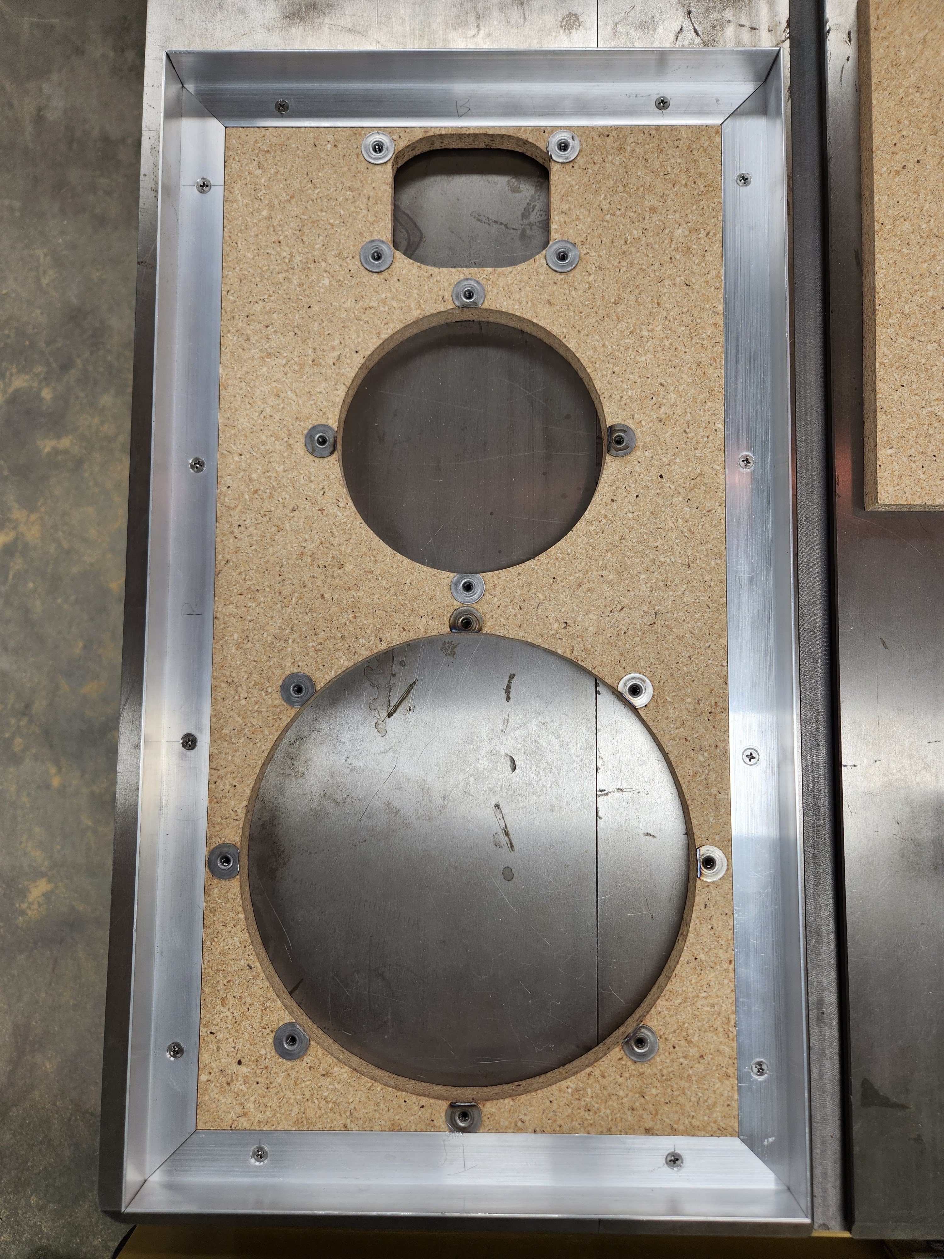
I got all of my T-nuts installed and trimmed them down to size with my Dremel and they turned out great.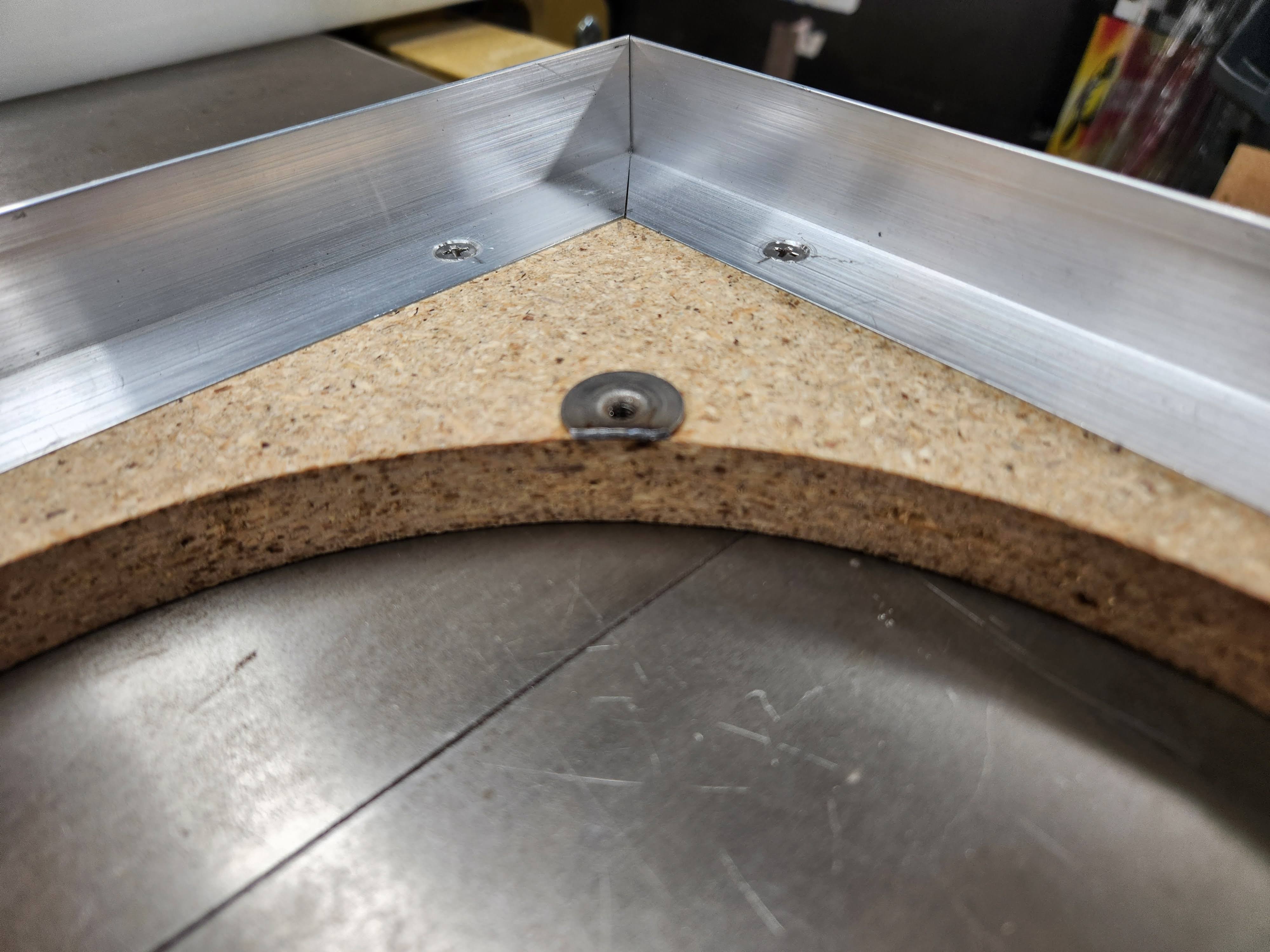
I thought about spot welding the aluminum at each corner due to potential rattling concerns but the more I think about, I don't think it will be an issue. These channels will be very firmly secured once we're all done.
Thank you for following along, stay tuned for more to come!
-
Fuses that were installed upon pickup (!!):
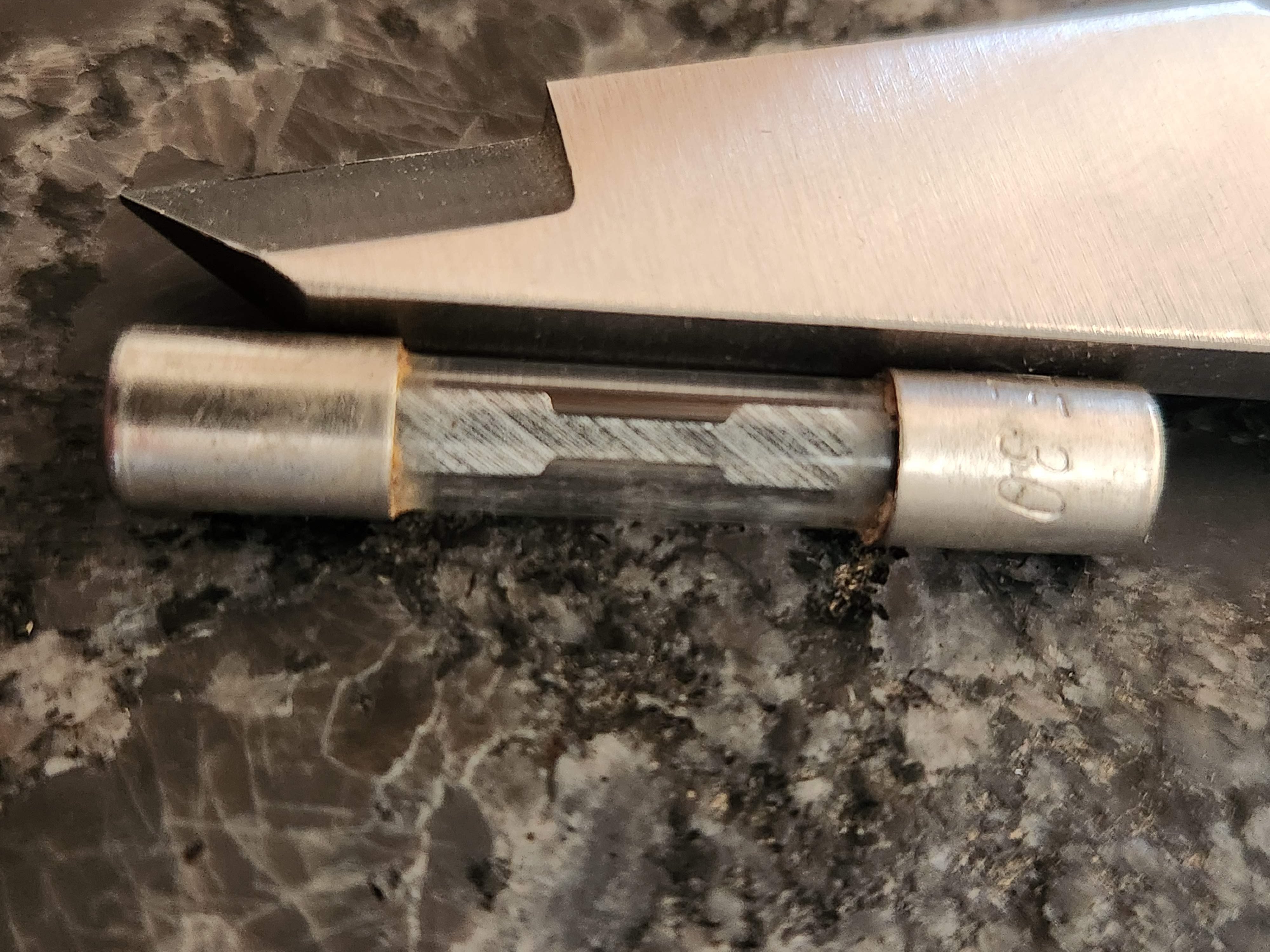
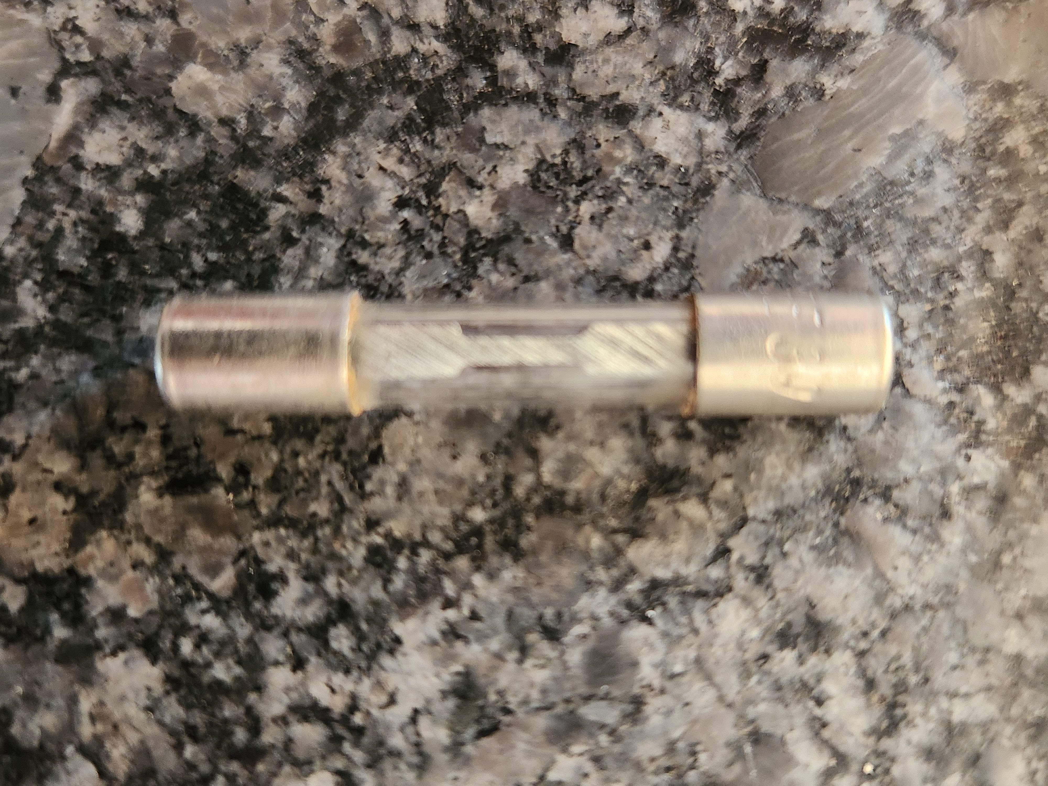
I mentioned before they were 20A fuses. Look again! 30A! -
Which tweeters do you plan on using?
-
Audax?Don't take experimental gene therapies from known eugenicists.
-
I have some period correct Peerless tweeters I will be installing in these, same as original
-
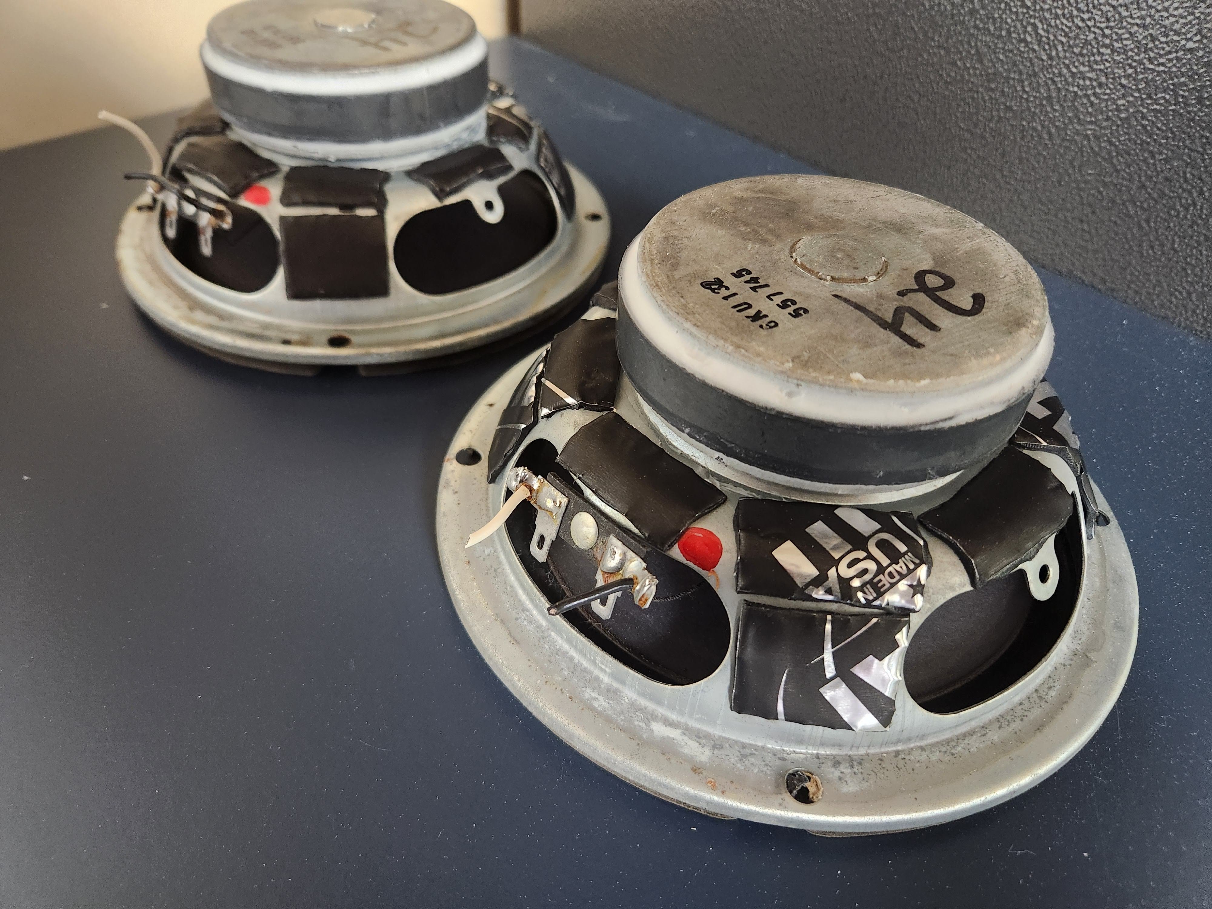
I have seen some pretty good looking Dynamat jobs on some of these speakers and well, I don't think this quite compares, but, it should get the job done nonetheless. I actually picked up a small amount of generic butyl sound deadening mat at Autozone locally without spending an arm and a leg. I will try to dig up a link but basically it's a small kit designed for car speakers. I have installed brand name Dynamat in a couple of vehicles before and while it is a little thicker than what I used, it's pretty much the same thing as far as I can tell. After applying the butyl squares, the basket ring disappeared. Very solid thud now if I flick the baskets with my thumbnail. Passive radiators received the same treatment of course.
I took the opportunity to get the driver magnets glued in place, on both ends, using Loctite Power Grab. This seems to be the preferred product for this application and I can see why. It's very solid once dry and I think it's pretty forgiving when applying it. Came out pretty good.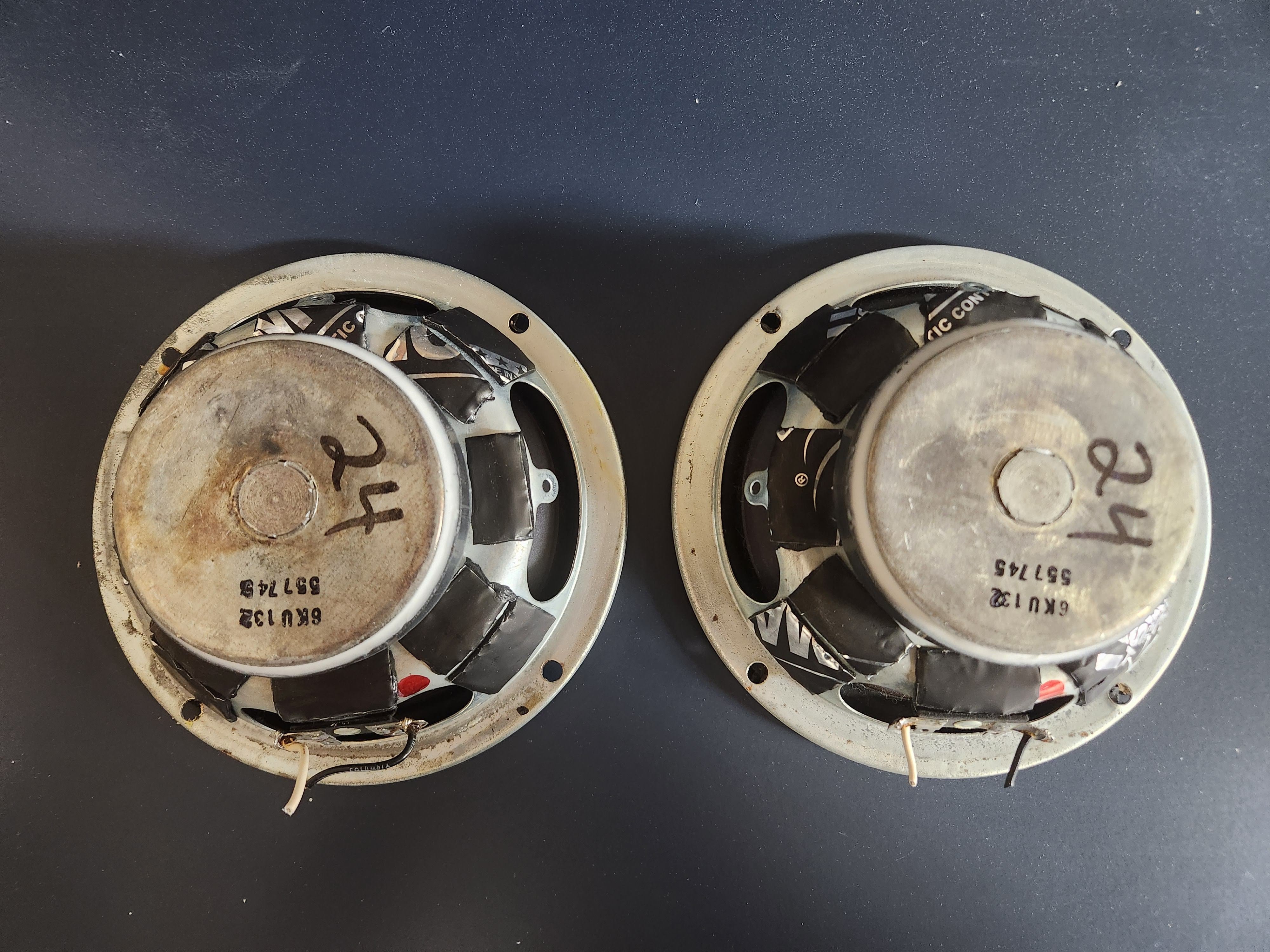
-
There's no valid reason to cover the entire basket as some have done. A piece on each spoke is more than enough.
While Loctite Power Grab was in vogue for a time JB Weld is back to the preferred adhesive.Political Correctness'.........defined
"A doctrine fostered by a delusional, illogical minority and rabidly promoted by an unscrupulous mainstream media, which holds forth the proposition that it is entirely possible to pick up a t-u-r-d by the clean end."
President of Club Polk -
Have to say, I’m impressed that you put that much into those cabinets. You will have a fine set of garage speakers.
I would probably just paint them some sort of black texture, make some hanging brackets, and hang them from the ceiling..
Enjoy the process/project..
Nice Job.. -
Time for crossovers. I know there are A LOT of different opinions when it comes to this subject, so I will try my best to make my case for what I did.
I decided to replace capacitors, resistors, wiring, terminals, fuse clips and of course new, properly rated fuses were installed. I know there is a lot of advice out there saying to remove the fuses, only use certain kind of caps, certain kind of resistors, etc. Here's my take on crossovers: you can always change them in the future if you decide you want to. None of what I did is permanent, minus the holes drilled in the back for the passage of wiring going to my new fuse clips (yes, the old ones were in very bad shape, not really worth trying to save.) I know there are some who would advise to simply remove the fuses, but I opted to leave them in place for now. I changed my caps and resistors out with Dayton Audio components from Parts Express. I know some people love these, and some people hate them. I will say that while I haven't heard them yet, I like the price and I really do have to try to maintain a budget on these. Maybe I hate them and upgrade in the future. Clarity caps seem to be popular along with Mills resistors. I may revisit this in the future. I will admit, with the new fuse clips being quite a bit bigger than the old, it does look a little funky when looking at the back of the crossovers, but then again, nothing about these is normal so far so it is kind of in theme with everything else lol.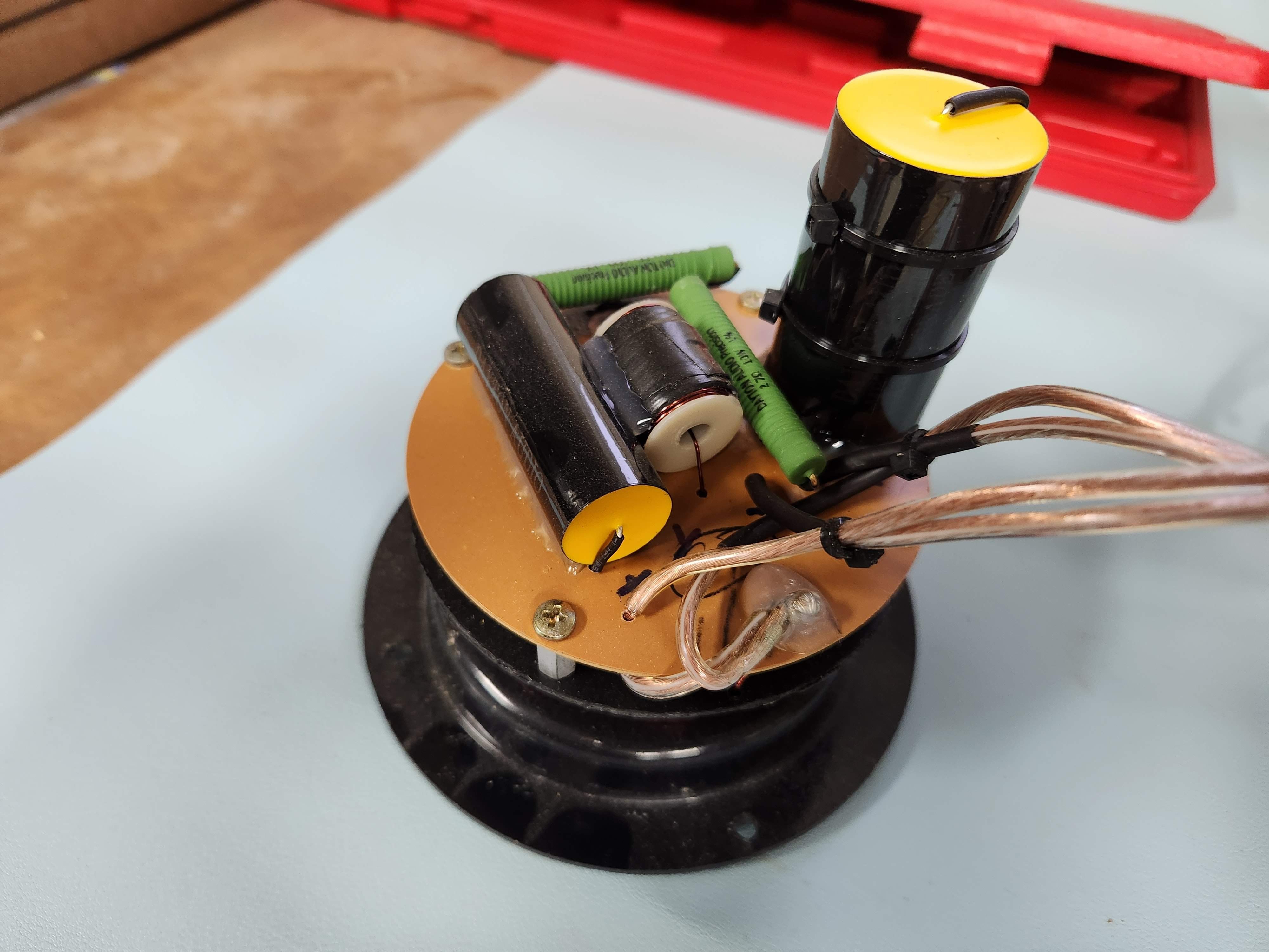
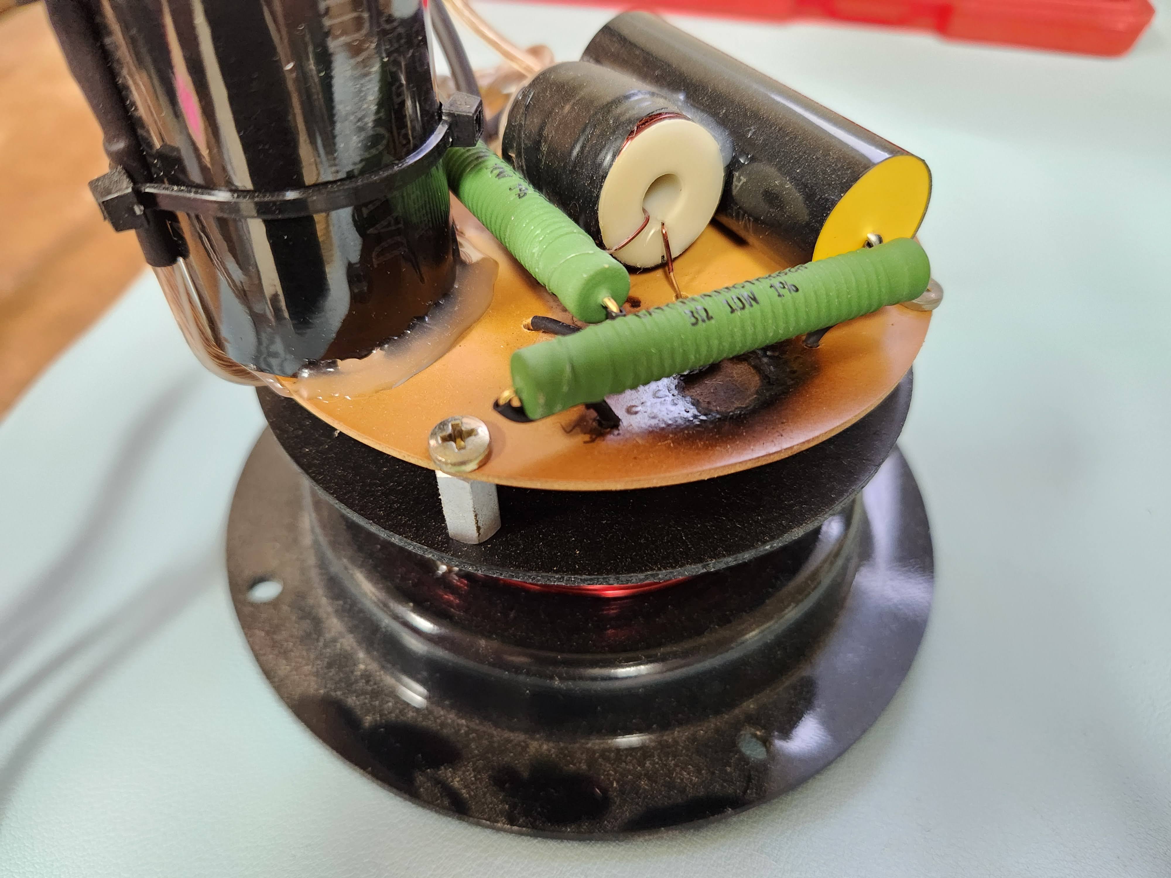
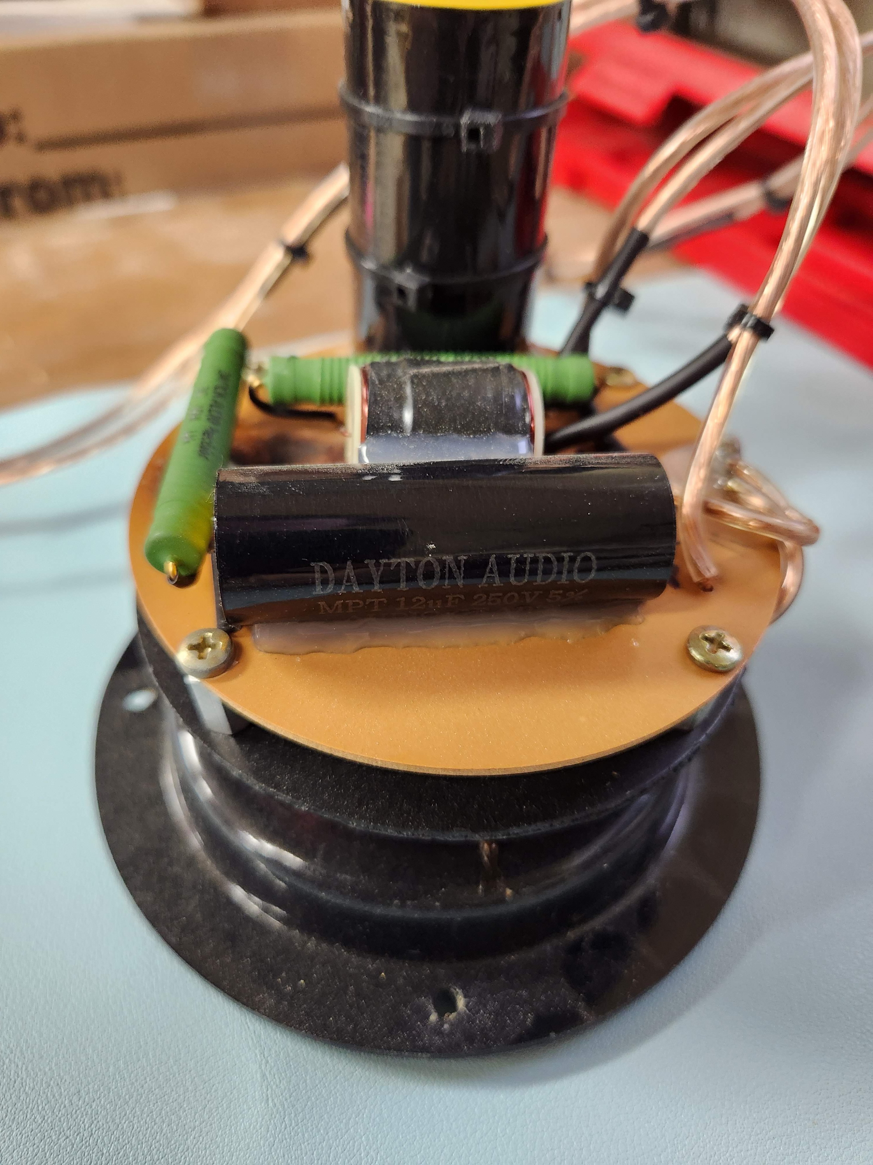
You'll notice in pic #2, how scorched the board is underneath the resistor. Old one was pretty smoked. Replaced with a higher wattage Dayton Audio resistor. Tried to give them a little more space from the board to breathe although I suspect this is related to those 30A fuses being in place.
Okay well here they are as seen from the outside of the cabinet. Let me have it. They're funky looking, I know.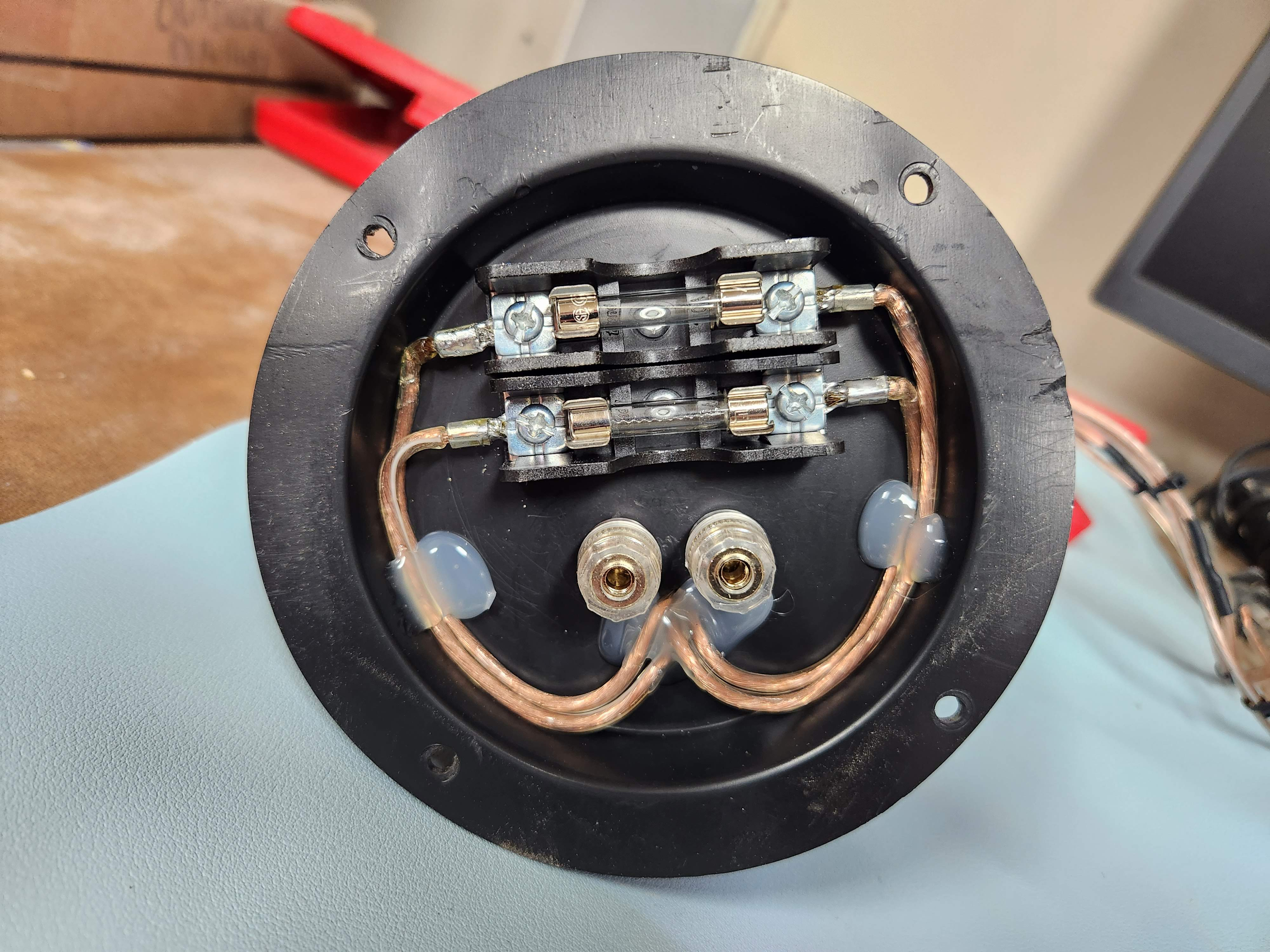
The plastic bodies that hold the crossover assemblies together in these speakers are in rough shape (surprised?). While they aren't in poor enough shape for me to justify replacing them, I did take the time to draw them out in Fusion just to have them on record. I could at a later time 3D print some of these. It is expensive but I have used MJF printing with excellent results. When I have things apart, a lot of the time I like to draw certain components, you never know when it might come handy in the future.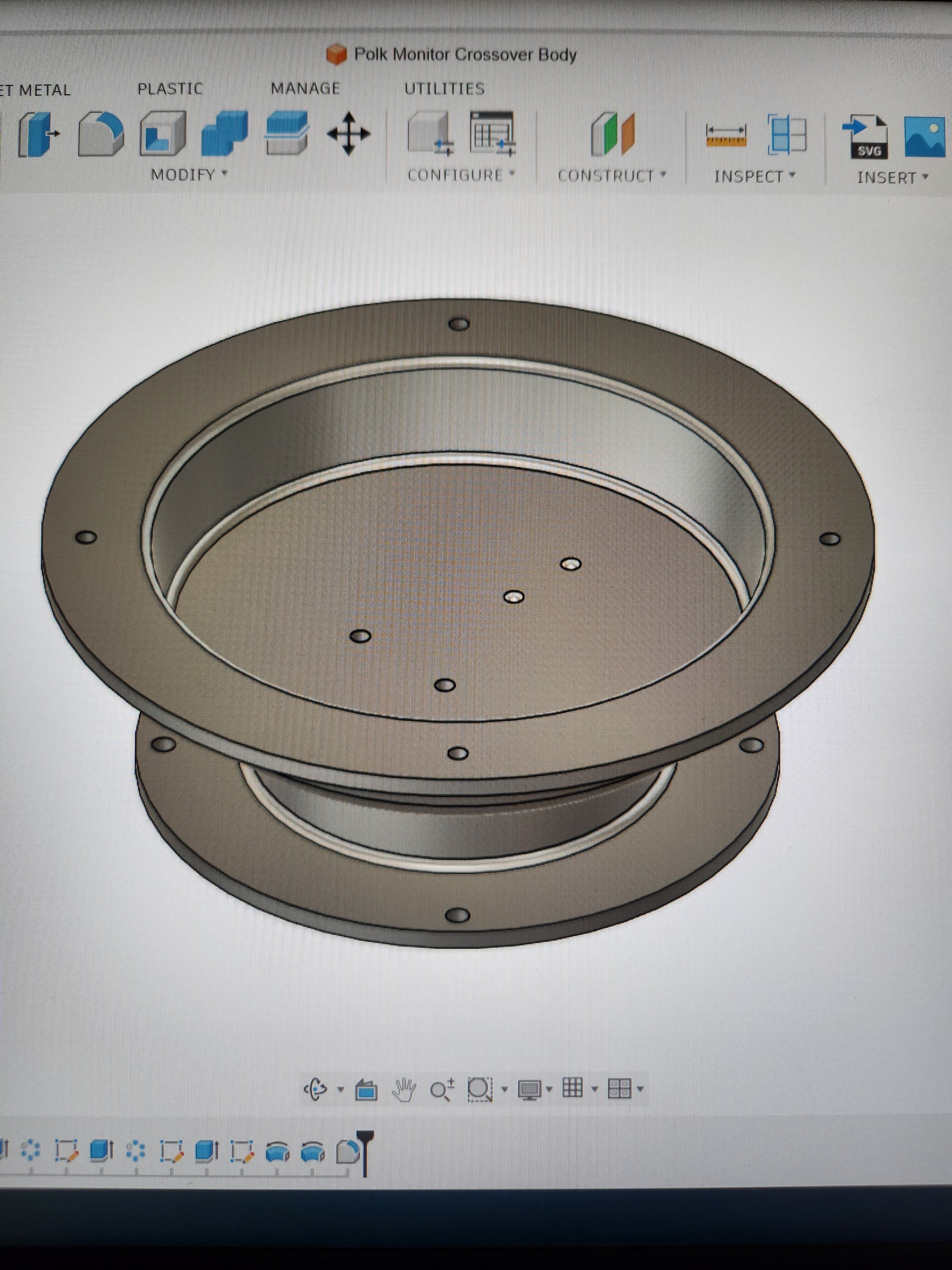
-
Thanks everyone for chiming in so far. It's fun to share this with people who appreciate the work that a lot of the time has to go into keeping these old speakers singing!
I will share the rest of my plans for these with everyone now:
1) I plan to laser cut some gaskets from a blank sheet of gasket material that I had purchased from McMaster-Carr awhile back. I don't have the roll in front of me so no specs to provide yet but I do think it will get the job done of keeping these cabinets air tight. I have generated .dxf files from Fusion for cutting with a small 40W laser.
2) While on my little Parts Express shopping spree I picked up some new grille cloth, so I will replace the old cloth with new to help make these look a little better. I also have some old Polk Audio badges laying around that are going to work perfectly for these as they were missing when I bought the speakers.
3) Paint the baffles with color matched paint I had mixed at Lowe's. Yes, they are going to be the same old shade of brown as they were before. I wanted to try to keep these looking closer to what they originally would have looked like.
That's pretty much the gist of everything!
Later on I will have something even more involved to share with everyone. I plan on building a pair of Monitor 7Cs from scratch. I have nearly everything I need to make that happen so I'm very excited. It's going to be a lot of fun but for now I'm just glad to be making progress with these 7As!
One more thing I did want to add is that I plan on making some proper router templates from these. It will make producing any more of these in the future a breeze. I don't think I will need to make any more 7A baffles for myself in the future, but you never know, maybe someone else will Post edited by Private_Idaho on -
Have to say, I’m impressed that you put that much into those cabinets. You will have a fine set of garage speakers.
I would probably just paint them some sort of black texture, make some hanging brackets, and hang them from the ceiling..
Enjoy the process/project..
Nice Job..
Truck bedliner is now en vogue. Hanging Polks I don't know.Don't take experimental gene therapies from known eugenicists. -
People don't love Dayton (same as Bennic) caps because they sound good. They love them because they are ignorant to what good caps sound like.
Here's some reading for you. Scroll down to the Bennic XPP, which is exactly the same as Dayton.
https://www.humblehomemadehifi.com/Cap.htmlPost edited by F1nut onPolitical Correctness'.........defined
"A doctrine fostered by a delusional, illogical minority and rabidly promoted by an unscrupulous mainstream media, which holds forth the proposition that it is entirely possible to pick up a t-u-r-d by the clean end."
President of Club Polk