Polk Monitor 7b - tweeter not working after recap

St0nes0de
Posts: 4
Hi there!
First post here, I’ve lurked around for years reading thru a bunch of Monitor series posts. I finally decided it was time to recap my Monitor 7Bs with Peerless tweeters and got around to working on one of the crossovers tonight.
Just hooked up the newly recapped speaker to do an A/B test, and the tweeter suddenly isn’t working. I am alarmed because both speakers were working great, I listened to them right before I decided to recap one of them. I thought maybe I had pulled one of the wires off of the driver while working on the x-over, but everything was connected as it should be. I switched the cables from the other speaker in case maybe my amp suddenly decided to go wonky, but still encountered the same issue. I also checked the fuse, and it looks good. I’m kinda stumped at this point and wondering if anyone has an idea of what I might’ve done wrong.
My pair is from 1983 and have the standard 7B crossover design:
12 uf cap
34 uf cap
2.7 ohm resistor
4.5 ohm resistor
Fused
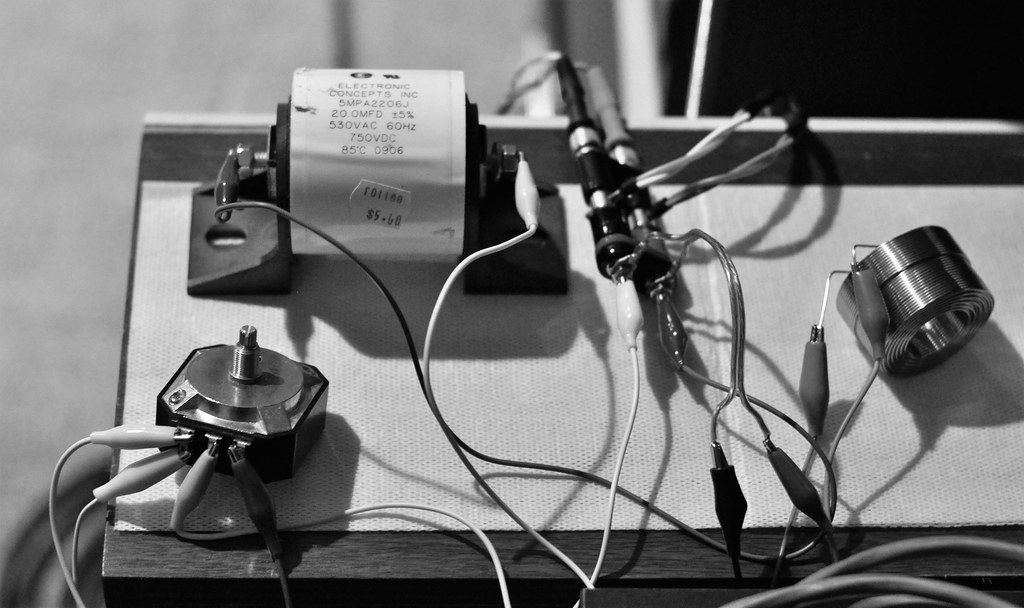
I went with Clarity CSA caps (12uf and 33uf) and Mundorf resistors (2.7 and 4.7 ohm). I ordered MOX series for both resistors, but was sent the MResist Supreme series for the 4.7 ohm parts. The parts are enormous, but you can see in the pics that I was able to get them to fit fine enough. You’ll also notice from the pics that I am still learning to solder (this was my second time). I was very methodical and only replaced one part at a time to avoid **** something up, but does anyone notice anything obviously wrong on the board? I figured the slightly higher resistance and wattage of the MResist parts would be fine, but maybe I was wrong?
I’ve read enough here to know that the fuse terminal/wires on these get pretty nasty over time and most folks replace or bypass the fuses when they recap…could that be the problem here?
First post here, I’ve lurked around for years reading thru a bunch of Monitor series posts. I finally decided it was time to recap my Monitor 7Bs with Peerless tweeters and got around to working on one of the crossovers tonight.
Just hooked up the newly recapped speaker to do an A/B test, and the tweeter suddenly isn’t working. I am alarmed because both speakers were working great, I listened to them right before I decided to recap one of them. I thought maybe I had pulled one of the wires off of the driver while working on the x-over, but everything was connected as it should be. I switched the cables from the other speaker in case maybe my amp suddenly decided to go wonky, but still encountered the same issue. I also checked the fuse, and it looks good. I’m kinda stumped at this point and wondering if anyone has an idea of what I might’ve done wrong.
My pair is from 1983 and have the standard 7B crossover design:
12 uf cap
34 uf cap
2.7 ohm resistor
4.5 ohm resistor
Fused
I went with Clarity CSA caps (12uf and 33uf) and Mundorf resistors (2.7 and 4.7 ohm). I ordered MOX series for both resistors, but was sent the MResist Supreme series for the 4.7 ohm parts. The parts are enormous, but you can see in the pics that I was able to get them to fit fine enough. You’ll also notice from the pics that I am still learning to solder (this was my second time). I was very methodical and only replaced one part at a time to avoid **** something up, but does anyone notice anything obviously wrong on the board? I figured the slightly higher resistance and wattage of the MResist parts would be fine, but maybe I was wrong?
I’ve read enough here to know that the fuse terminal/wires on these get pretty nasty over time and most folks replace or bypass the fuses when they recap…could that be the problem here?
Comments
-
Do you have a meter? If so it is definitely time to do some resistance checks. The schematic below that some unknown person did up is rough and you and I both have the version with 4.5ohms (not 4.7), but should allow you to do the tests. Start by disconnecting the tweeter and check the DC resistance, which should be around 7 to 8 ohms (seems to have varied in production from Peerless). Then check from the outside of the fuse block to the other side of the 4.5 ohm and then from the + binding post to the other side of 4.5ohm. Then check the 2.7 ohm and the small inductor with the tweeter still disconnected.
Did you have quick disconnects to the drivers from Polk or did you (like me) have to desolder and convert to the fastons? The Peerless tweeter could get damaged from the desoldering process if not done correctly, which is why most people cut the existing wires an inch or so away and put a male faston on there.


This solder joint needs to be cleaned, fluxed, and reflowed but as far as I can tell it is one end of the 34uF cap for the MW6500
Post edited by Gardenstater onGeorge / NJ
Polk 7B main speakers, std. mods+ (1979, orig owner)
Martin Logan Dynamo sub w/6ft 14awg Power Cord
Onkyo A-8017 integrated
Logitech Squeezebox Touch Streamer w/EDO applet
iFi nano iDSD DAC
iPurifier3
iDefender w/ iPower PS
Custom Steve Wilson 1m UPOCC Interconnect
iFi Mercury 0.5m OFHC continuous cast copper USB cable
Custom Ribbon Speaker Cables, 5ft long, 4N Copper, 14awg, ultra low inductance
Custom Vibration Isolation Speaker Stands and Sub Platform -
Yep there are several rough spots i'd heat up and reflow some solder.
-
Many thanks for the replies.
After looking at the crossover again, you were both correct in your assessment of my solder joints; most of them were really gnarly. I cleaned and reflowed all of the joints on the new components, and I wouldn’t necessarily say they’re pretty, but everything is cleaner and much improved. I’m pretty sure my tip was oxidized and I was soldering at too low a temp. I took great care to clean my iron this time around to much better results. I am currently doing the resistance checks per your recommendation @Gardenstater.
Luckily my Peerless have the quick disconnects, so no worry of damaging the tweeter when disconnecting. I’m reading 7.9 ohms across the tweeter, so all good there. Thanks for the tip about cutting the wires an inch or so from the terminals to avoid damaging the drivers, that’s great advice for future projects.
It looks like the resistance between the fuse box and the 4.7 resistor is 5.3 ohms. Resistance is the same between the resistor and the positive terminal: 5.3 ohms. And I’m reading 1.1 ohms between the small inductor and the 2.7 resistor. -
Luckily my Peerless have the quick disconnects, so no worry of damaging the tweeter when disconnecting.
The tabs on the Peerless tweeters are very weak and break off easily. You would be wise not to mess with them.Political Correctness'.........defined
"A doctrine fostered by a delusional, illogical minority and rabidly promoted by an unscrupulous mainstream media, which holds forth the proposition that it is entirely possible to pick up a t-u-r-d by the clean end."
President of Club Polk -
It looks like the resistance between the fuse box and the 4.7 resistor is 5.3 ohms. Resistance is the same between the resistor and the positive terminal: 5.3 ohms.
That's good because it shows that there is no problem with the binding post/fuseblock/fuse wiring or the resistor that would keep the tweeter from playing.
If you want to see how oxidized the fuseblock wiring is you can remove the fuse and measure from the + binding post to the left side of the fuseblock and then from the right side of the fuseblock to the near side of the 4.5 (or 4.7) ohm resistor. You might get something like 0.5 ohms instead of 0 which would be ideal.And I’m reading 1.1 ohms between the small inductor and the 2.7 resistor.
Not sure what point to point you are reading here. Across the small inductor with tweeter disconnected you should get around 1.3 ohms. Then reading across the white and black tweeter wires at the quick disconnects you should get around 4.0 ohms, which is the 1.3 plus the 2.7 ohm resistor.
As far as the tweeter 12uF capacitor is concerned it shouldn't be shorted. If you read from the right side of the fuseblock to the black (or white for that matter) wire for the tweeter you should get no reading (open). You need a capacitance meter to make sure that the cap is good if it passes the short test.
George / NJ
Polk 7B main speakers, std. mods+ (1979, orig owner)
Martin Logan Dynamo sub w/6ft 14awg Power Cord
Onkyo A-8017 integrated
Logitech Squeezebox Touch Streamer w/EDO applet
iFi nano iDSD DAC
iPurifier3
iDefender w/ iPower PS
Custom Steve Wilson 1m UPOCC Interconnect
iFi Mercury 0.5m OFHC continuous cast copper USB cable
Custom Ribbon Speaker Cables, 5ft long, 4N Copper, 14awg, ultra low inductance
Custom Vibration Isolation Speaker Stands and Sub Platform -
A couple of thoughts. The heat of soldering/desoldering/resoldering can do damage to components, so be careful, especially if you (@St0nes0de) aren't quite experienced with the technique. This is especially true for the voice coil of the tweeter! @F1nut also noted the physical fragility of the tweeter's connections. Do be careful.
Now and in the future: If you're troubleshooting connections, and for mocking up a simple crossover like this one before slinging solder -- a bag of clipleads could be your best friend!") I'd urge youto get some now or, at the least, before your next project.
I'd urge youto get some now or, at the least, before your next project.
Here's an example:
https://www.parts-express.com/Small-Alligator-Clip-Test-Lead-Set-10-Pcs.-360-150?quantity=1

One final comment, which I offer with some trepidation:")
I think that one of the more salient failure modes for soldering can be using too little heat for too long a time. Use the right sized soldering tool for the job, and the right temperature for the solder being used. A quick, surgical strike (in and out quickly) is usually the best practice for good solder joints with minimal chance of damage to sensitive components. Most of the crossover components are pretty tough, but the drivers themselves (particularly tweeters) are fairly sensitive to heat.
Hope this is helpful, even if a bit tangential to the question and to the discussion so far.
-
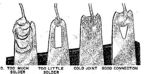
With a little experience, the Gestalt of a good solder joint is pretty easy to recognize. Sorry this image (from either EICO or Heathkit) isn't better! Solder isn't glue. There should be a good, solid mechanical connection between components before adding solder to the joint.

-
A quick, surgical strike (in and out quickly) is usually the best practice for good solder joints with minimal chance of damage
FWIW: On my soldering station I set the temp at 600+ degrees, of course my solder melts at about 1/2 that but as @mhardy6647 stated I can get on and get out with a good joint quickly. In most instances there is little worry of a cold solder joint. -
Cardas Quad is a soldering neophyte's best tool.Don't take experimental gene therapies from known eugenicists.
-
A lot of really great advice and info here, thank you all!
Copy that, @F1nut, I did notice that the tabs on the Peerless seemed quite fragile. Luckily I was able to disconnect each wire without exerting too much force on the tabs.
I watched several different videos on basic soldering/desoldering technique yesterday before cleaning and redoing my work, and for me, the main takeaway was to always keep the tip clean and try to apply higher temp for shorter periods of time (as @mhardy6647 and @pitdogg2 both suggested). I’d say my understanding and technique have improved greatly since that little refresher course, though I am eager to get some more practice. Thanks a lot @mhardy6647 for your detailed and insightful replies.
I remeasured resistances per your suggestions @Gardenstater and am getting the expected values across the small inductor and the wire disconnects: 4.0 ohm. Also did the check for a shorted 12uf capacitor and am getting an open reading from the right side of the fuseblock to the end of the black wire disconnect.
Checking the fuseblock wiring on each side as you describe, I am getting 0.1 ohm for each. This means little to no oxidation in the wires, correct? If this is the case, is it a problem to leave the fuse in the circuit as opposed to bypassing it? Would it affect sound quality to have the fuse remain in the circuit with the additional .2 ohms of resistance from the new 4.7 resistor?
Following the new round of resistance checks, it seems like everything may be in order now. I am going to reassemble the speaker and test it out this evening after work. Wish me luck!
-
I guess I'd have to say that 0.1 is very low but you would prefer it to be reading 0 even with a (assuming?) low resolution meter. The 1 A fuse should add another 190 milliohms cold. What do you get with the fuse installed and going from the + binding post to the near side of the 4.5 (or 4.7) ohm resistor?
I personally elected to retain my fuse and fuseblock but I rewired it with Cardas Litz wire, which wasn't for the faint of heart. I was able to spot drill the copper plated steel rivet (I initially thought it might be solid copper and was disappointed) and solder the litz wire to it without melting the plastic. Must be a high temp thermosetting plastic. The only reason I kept it is because I'm using a vintage Crown D150 amp which for all I know has never been serviced. Doesn't appear to have any new parts inside.
If you trust your amplifier to have more than enough clean power and especially if it has some good speaker protection built in like relay protection, then it would be best to eliminate the fuse and fuseblock. I know Danny Ritchie is constantly saying how bad it is to have any ferrous metals in the signal path. The other option would be to solder to the tabs on the fuseblock but then the wires would show partially on the back of the speaker before they go inside to the crossover.George / NJ
Polk 7B main speakers, std. mods+ (1979, orig owner)
Martin Logan Dynamo sub w/6ft 14awg Power Cord
Onkyo A-8017 integrated
Logitech Squeezebox Touch Streamer w/EDO applet
iFi nano iDSD DAC
iPurifier3
iDefender w/ iPower PS
Custom Steve Wilson 1m UPOCC Interconnect
iFi Mercury 0.5m OFHC continuous cast copper USB cable
Custom Ribbon Speaker Cables, 5ft long, 4N Copper, 14awg, ultra low inductance
Custom Vibration Isolation Speaker Stands and Sub Platform -
Well, I finally got around to reassembling the speaker to test it out just now. The issue must have been my poor soldering work because both drivers are firing and sound great!
Of course I was expecting to hear an improvement following the recap, but after a quick A/B test, I am astonished at how much the sound has opened up compared to the other speaker. I thought they sounded great before, but WOW…
@Gardenstater, before hooking this up to test, I measured the fuseblock with the fuse inserted in the terminal. I read what you said I should expect: 0.29 ohms with the additional 0.19 ohms from the fuse. I think I will keep the fuses for now, but will likely bypass them at some point in the future. I am currently running a vintage HK PM640, which is in pretty good condition, but like your amp, does not appear to have been serviced anytime in the recent past. No speaker relay in the PM640, so it would probably be wise to keep the fuses, as you suggest.
Going to do the other speaker now so I can listen to these bad boys together. By most accounts they’ll sound even better after 100 hours or so…can’t wait.
Thanks again to all you fine folks for the helpful information and advice! I’ve learned a ton thru this experience and have some rugged 7Cs that I’m looking forward to fixing up, so I may pop in again at some point seeking more advice.