HH Scott 340 Receiver Rebuild
Options

SCompRacer
Posts: 9,212
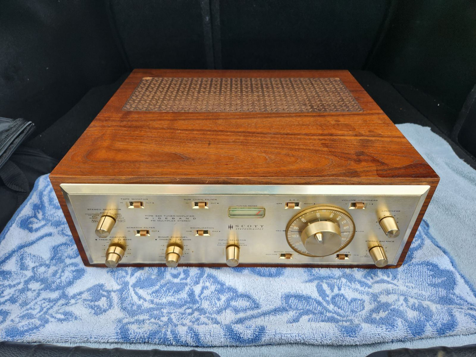
A project for a good friend. HH Scott 340 receiver. I agreed to refurb it before realizing how much effort would be required.  But it's all good otherwise I'd have nothing to do. I've been bothering Ken about some details and mhardy might be next.
The multi-value can capacitors will be replaced first. There can be up to four values of same or different value capacitor in each can. Can is marked for values with symbols that match symbols on bottom wafer.
There are multiple ways to replace these can style electrolytic capacitors. CE Manufacturing® builds new multi-section electrolytic "can" capacitors on the original vintage Mallory machinery. They have a video page with three videos showing the process. They are priced around $40 - $50 each but don't offer custom builds that I am aware of. The Scott 340 needs four cans. One 75uf @ 450v x 4, one 20uf @ 450v x 2 with 25uf @ 25v x 2, one 30uf @ 500v x 2 and one 20uf @ 450v x 4.
https://www.cemfg.com/can-capacitors
Hayseed Hamfest is another source for can capacitors. They stuff new cans with modern caps. Brands used are Nichicon, United Chemi-Con, Panasonic, Illinois Capacitor, Rubycon, Roderstein, etc.. They offer can kits for some gear like Fisher, HH Scott, McIntosh. They also offer a custom quote form for values not listed. The kit for a HH Scott 299D is close to what I need for $167. They are in the UK so unsure of what shipping might cost.
https://hayseedhamfest.com/
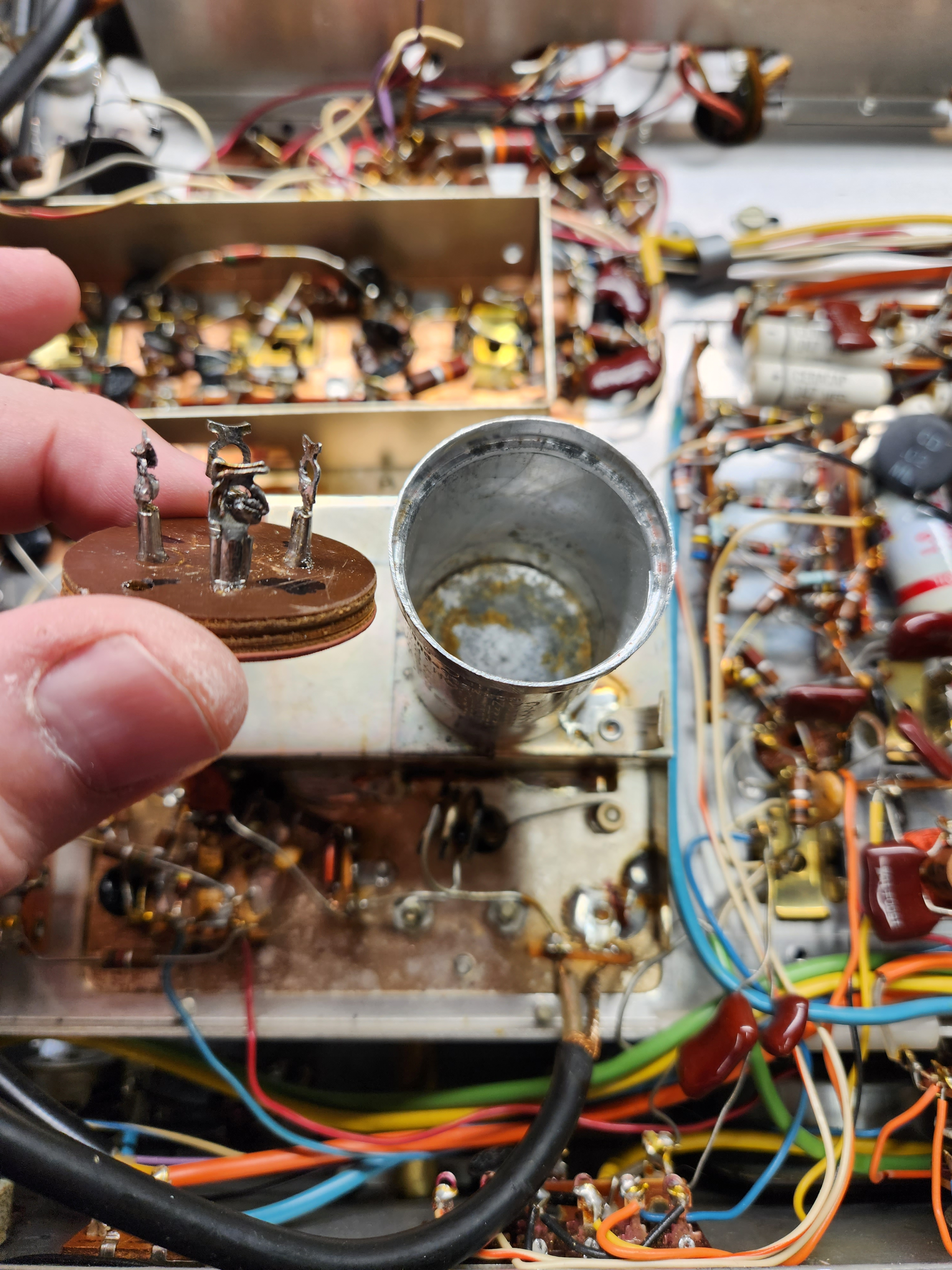
Another way, if you have the room, is install modern caps on terminal strips in the chassis. While modern caps are smaller, there is not enough space for the fourteen values this 340 needs, so I chose the disassemble, clean and restuff the can method. It's labor intensive but lowest cost. I chose Nichicon UCY 12,000 hour rated caps. IIRC cost was 50 bucks for all values needed.
I file the rolled edge off can and careful remove the wafers. After that, some large screws, some heat and brute force to pull it out. I did it in garage as it stunk when opened. Some folks cut the can. Some use side cutters and roll the edge back. The procedure I chose, the can will slide onto the round wafers. There is a stack of three wafers. By removing one layer, I can reroll the edge over the ring with tabs. You need those tabs to attach it to wafer riveted to chassis.
I'll do the 75uf/75uf/75uf/75uf @ 450v/450v/450v/450v common positive, yes, positive ground, can first. Once the new caps arrive, I'll see if I can fit the rest in the chassis. The other three cans are common negative ground.
Adapt a cap makes a small circuit board that fits modern caps and rivets/nut-bolts to chassis. You have to figure out how to attach the can to cover them. A guy on ebay supplies a similar can kit with round wafer that can fits on. I don't want any exposed caps above the chassis and want to keep the original appearance.


The multi-value can capacitors will be replaced first. There can be up to four values of same or different value capacitor in each can. Can is marked for values with symbols that match symbols on bottom wafer.
There are multiple ways to replace these can style electrolytic capacitors. CE Manufacturing® builds new multi-section electrolytic "can" capacitors on the original vintage Mallory machinery. They have a video page with three videos showing the process. They are priced around $40 - $50 each but don't offer custom builds that I am aware of. The Scott 340 needs four cans. One 75uf @ 450v x 4, one 20uf @ 450v x 2 with 25uf @ 25v x 2, one 30uf @ 500v x 2 and one 20uf @ 450v x 4.
https://www.cemfg.com/can-capacitors
Hayseed Hamfest is another source for can capacitors. They stuff new cans with modern caps. Brands used are Nichicon, United Chemi-Con, Panasonic, Illinois Capacitor, Rubycon, Roderstein, etc.. They offer can kits for some gear like Fisher, HH Scott, McIntosh. They also offer a custom quote form for values not listed. The kit for a HH Scott 299D is close to what I need for $167. They are in the UK so unsure of what shipping might cost.
https://hayseedhamfest.com/
Another way, if you have the room, is install modern caps on terminal strips in the chassis. While modern caps are smaller, there is not enough space for the fourteen values this 340 needs, so I chose the disassemble, clean and restuff the can method. It's labor intensive but lowest cost. I chose Nichicon UCY 12,000 hour rated caps. IIRC cost was 50 bucks for all values needed.
I file the rolled edge off can and careful remove the wafers. After that, some large screws, some heat and brute force to pull it out. I did it in garage as it stunk when opened. Some folks cut the can. Some use side cutters and roll the edge back. The procedure I chose, the can will slide onto the round wafers. There is a stack of three wafers. By removing one layer, I can reroll the edge over the ring with tabs. You need those tabs to attach it to wafer riveted to chassis.
I'll do the 75uf/75uf/75uf/75uf @ 450v/450v/450v/450v common positive, yes, positive ground, can first. Once the new caps arrive, I'll see if I can fit the rest in the chassis. The other three cans are common negative ground.
Adapt a cap makes a small circuit board that fits modern caps and rivets/nut-bolts to chassis. You have to figure out how to attach the can to cover them. A guy on ebay supplies a similar can kit with round wafer that can fits on. I don't want any exposed caps above the chassis and want to keep the original appearance.
Salk SoundScape 8's * Audio Research Reference 3 * Bottlehead Eros Phono * Park's Audio Budgie SUT * Krell KSA-250 * Harmonic Technology Pro 9+ * Signature Series Sonore Music Server w/Deux PS * Roon * Gustard R26 DAC / Singxer SU-6 DDC * Heavy Plinth Lenco L75 Idler Drive * AA MG-1 Linear Air Bearing Arm * AT33PTG/II & Denon 103R * Richard Gray 600S * NHT B-12d subs * GIK Acoustic Treatments * Sennheiser HD650 *
Comments
-
Will be following this thread. Love HH Scott receivers.Don't take experimental gene therapies from known eugenicists.
-
Wow that's ambitious!
-
It should be worth it.
Plus, those Scott receivers were (are) absolutely gorgeous.
-
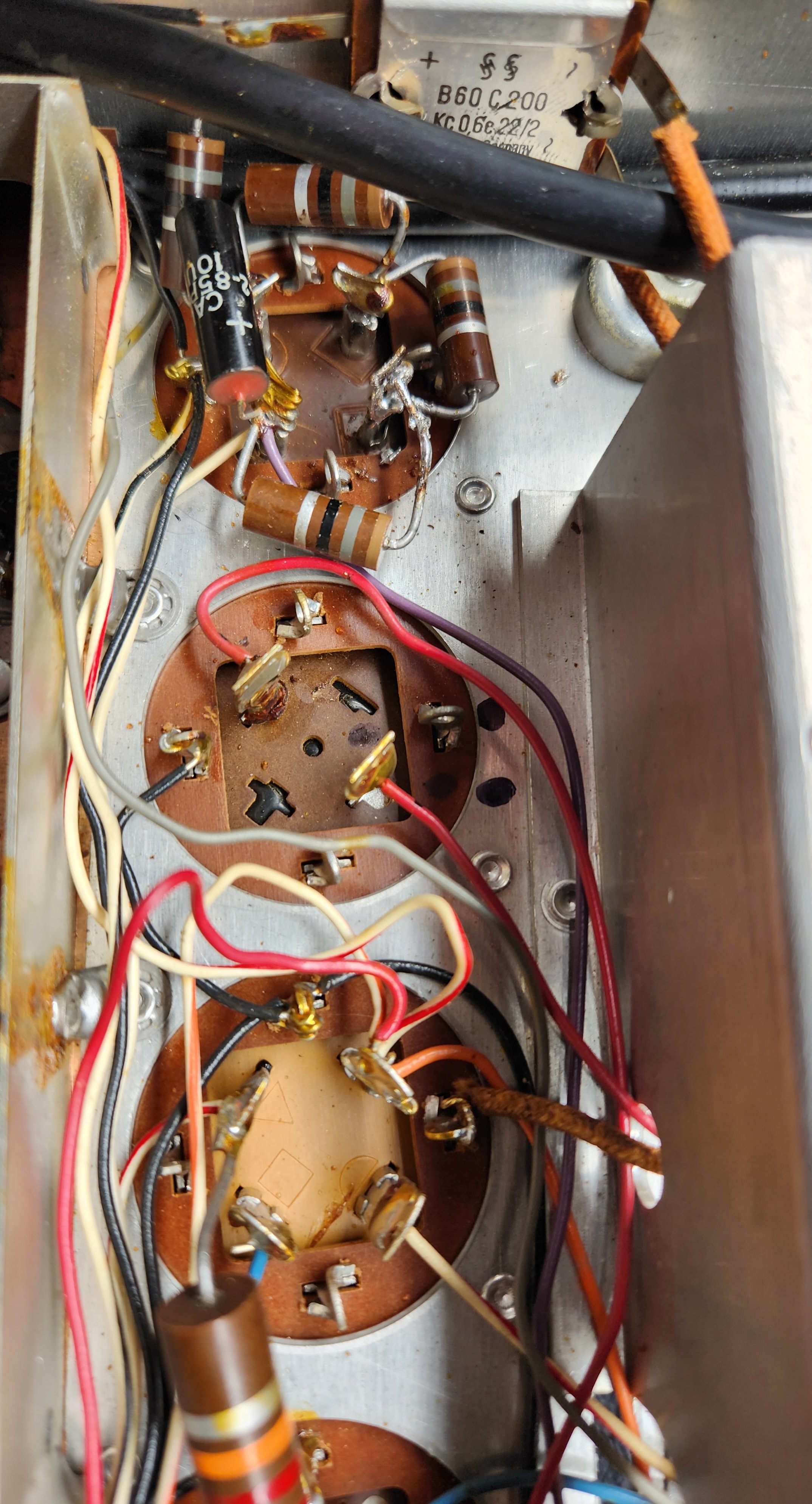
The busy work. The insides of switches can look like this selector. While some say the corrosion is conductive, I find not cleaning them can result in scratchy sound.
I'm using DeoxIT with makeup Q tips as they are more tightly wound than regular cotton swabs. Saturating the wafers with DeoxIT can cause issues without completely removing corrosion so I soak the Q tip with DeoxIT and lightly rub the metal without bending the contacts. I fold paper wipes and saturate to clean between contacts. I've read some guys use a dollar bill.
Still have a little more to do. The forward section of selector is much harder to get at.


Salk SoundScape 8's * Audio Research Reference 3 * Bottlehead Eros Phono * Park's Audio Budgie SUT * Krell KSA-250 * Harmonic Technology Pro 9+ * Signature Series Sonore Music Server w/Deux PS * Roon * Gustard R26 DAC / Singxer SU-6 DDC * Heavy Plinth Lenco L75 Idler Drive * AA MG-1 Linear Air Bearing Arm * AT33PTG/II & Denon 103R * Richard Gray 600S * NHT B-12d subs * GIK Acoustic Treatments * Sennheiser HD650 * -
Those switches are probably silver plated contacts and, fortunately, silver oxide is conductive. It looks grim but not so bad electrically. The Revox A77 has a sliding switch bar that makes dozens of contacts when the speed is changed or the deck is turned on and off. It uses silver contacts and it is hard to disassemble, clean and put back together. But satisfying when done.
-
Looking at your pics, there's no brittle PCBs to worry about
") Don't take experimental gene therapies from known eugenicists.
Don't take experimental gene therapies from known eugenicists. -
Parts starting to arrive! My eyes are crossed from all the researching about recapping the 340.
I stuffed and reassembled the 75uf @ 75v x 4 common positive can. I used Nichicon UCY 82uF 200v. It was the closest value to 75uf I could find. Hayseed Hamfest replaces this can with 100uf 100v. Negative leads are attached to the four terminals. I wound the leads around hole in terminal and tinned them. The positive leads connect to eyelet.
Cans are typically common negative ground, which means the can is tied to the negative terminal(s) of capacitor(s) in can. I've seen some gear where the cans are attached directly to chassis. On the Scott 340, the cans are attached to phenolic insulating wafers. A ground wire is then soldered to the can ground lugs.
The 18 Ohm one-watt 10% carbon resistors on the 75 x 4 were over 10% out of spec so I replaced them. One connects from the Selenium rectifier to first 75 Ohm, then three daisy chain along the remaining three 75 Ohm tabs.
I replaced the Callins 10uf 25v bypass with a Sprague Atom 10µF / 150V. I learned you can't always find exact uf or voltage replacements for vintage gear. I learned it's OK to use slightly higher uf and voltage caps.
The Scott 340 has two Callins electrolytic caps. The other, a 25uf 25v, was in tuner section buried under some Micas. I could see a crack in it. While researching I found a video on youtube showing one that cracked in pieces. I removed it and it was open inside. I read one should get rid of the Callins as they will crack and leak. I also learned Fred Callins co-designed the first viable miniature electrolytic capacitors for use in palm sized transistor radios.
For the 30uf @ 500v x 2 can next to it, I just did a terminal strip with two 33uf 500v over it. Once I turn it right side up, they will be under it.
I removed the third can and will disassemble, clean and stuff it. It's a 20uf @ 450v x 4. The fourth can I'll do a terminal strip in chassis.
Yes, I number wires so I don't get lost in reassembly.
And yes, I caught and rectified not soldering the resistor to the rectifier terminal and snipped the ground.


Post edited by SCompRacer onSalk SoundScape 8's * Audio Research Reference 3 * Bottlehead Eros Phono * Park's Audio Budgie SUT * Krell KSA-250 * Harmonic Technology Pro 9+ * Signature Series Sonore Music Server w/Deux PS * Roon * Gustard R26 DAC / Singxer SU-6 DDC * Heavy Plinth Lenco L75 Idler Drive * AA MG-1 Linear Air Bearing Arm * AT33PTG/II & Denon 103R * Richard Gray 600S * NHT B-12d subs * GIK Acoustic Treatments * Sennheiser HD650 * -
Impressive!
-
Are you renewing the wiring as you go or is the insulation still good after all these years?Don't take experimental gene therapies from known eugenicists.
-
Thanks Ivan!Are you renewing the wiring as you go or is the insulation still good after all these years?
So far, I have not encountered any burnt or brittle wiring so I'm not replacing wiring. It's like 22-gauge solid tinned wire. I've had to snip ends off some desoldered wiring and remove a little insulation and it's still pliable, no insulation cracking off. I'm able to loop wire around terminals and squeeze tight with needle nose before soldering.
I watched a video of a Scott 399 restoration, and that unit had some shorting that damaged some wiring.
Salk SoundScape 8's * Audio Research Reference 3 * Bottlehead Eros Phono * Park's Audio Budgie SUT * Krell KSA-250 * Harmonic Technology Pro 9+ * Signature Series Sonore Music Server w/Deux PS * Roon * Gustard R26 DAC / Singxer SU-6 DDC * Heavy Plinth Lenco L75 Idler Drive * AA MG-1 Linear Air Bearing Arm * AT33PTG/II & Denon 103R * Richard Gray 600S * NHT B-12d subs * GIK Acoustic Treatments * Sennheiser HD650 * -
All done with the four old electrolytic multivalve cans. Stuffed the first, installed two 33uf @ 500v under chassis for can two (30uf 500v original value). Stuffed can three with four 22uf @ 450v caps (20uf @ 450v original value). Fourth can under chassis with two 22uf 450v and two 27uf 160v (original value 20uf @ 450 and 25uf @ 25v). I had laid out all fourteen caps under there and I felt it was a little too tight to do them all in chassis.
I had two used, known good Sovtek 5AR4/GZ34. Stuck them in (no other tubes) and powered on through dim bulb tester with 75 watt bulb (I don't have a variac). No smoke, nothing getting hot.
Tested voltage at the 33uf 500v cap which gets fed from the two GZ34/5AR4, 357.9vdc. Since all looked well I removed the dim bulb tester and plugged it direct into wall and got 505.9vdc. Schematic shows 470v there but that's with all tubes in it. Mains voltage is higher now and can affect voltages and ability to adjust tube bias. I need to do more research on that.
Next up, a trip to Aaron's and test the tubes to see what's good and what's not. One 7951 is visibly bad, white inside and glass is loose. We have a mix of HH Scott (which could be original), Telefunken, Sylvania, RCA and some rubbed clean.
I'm going to try operation with all tubes before recapping the rest of unit. The carbon resistors on can three and four measured good so I reused them.
Voltage with dim bulb tester (mains voltage goes through bulb then to gear plugged in).
Voltage with dim bulb tester removed, plugged direct into wall. You can see I wrote symbols and values on chassis so I wouldn't screw up with the 20uf 450v and 25uf 25v values.
Multivalue cans have symbols next to values on outside of can that correspond with symbols on bottom of can. If you are stuffing one with different values, you have to ensure the value matches the symbol.

Post edited by SCompRacer onSalk SoundScape 8's * Audio Research Reference 3 * Bottlehead Eros Phono * Park's Audio Budgie SUT * Krell KSA-250 * Harmonic Technology Pro 9+ * Signature Series Sonore Music Server w/Deux PS * Roon * Gustard R26 DAC / Singxer SU-6 DDC * Heavy Plinth Lenco L75 Idler Drive * AA MG-1 Linear Air Bearing Arm * AT33PTG/II & Denon 103R * Richard Gray 600S * NHT B-12d subs * GIK Acoustic Treatments * Sennheiser HD650 * -
Very cool, Rich.Jay
SDA 2BTL * McCormack DNA 0.5 amp * Oppo BDP-93 * Modded Adcom GDA-600 DAC * Rythmik F8 (x2)
Micro Seiki DQ-50 * Mitsubishi LT-30 * Hagerman Cornet 2 Phono
Preamp rotation: Krell KSL (SCompRacer recapped) * Manley Shrimp * PS Audio 5.0 -
Very nice, and nice of you Rich. Looking at that puppy naked , lots of work. Must be a real good friend.. Looking forward to thoughts after all is done on the sound as I'm a big Scott fan myself.HT SYSTEM-
Sony 850c 4k
Pioneer elite vhx 21
Sony 4k BRP
SVS SB-2000
Polk Sig. 20's
Polk FX500 surrounds
Cables-
Acoustic zen Satori speaker cables
Acoustic zen Matrix 2 IC's
Wireworld eclipse 7 ic's
Audio metallurgy ga-o digital cable
Kitchen
Sonos zp90
Grant Fidelity tube dac
B&k 1420
lsi 9's -
Greetings Tony! Maybe it's a test of friendship...
Salk SoundScape 8's * Audio Research Reference 3 * Bottlehead Eros Phono * Park's Audio Budgie SUT * Krell KSA-250 * Harmonic Technology Pro 9+ * Signature Series Sonore Music Server w/Deux PS * Roon * Gustard R26 DAC / Singxer SU-6 DDC * Heavy Plinth Lenco L75 Idler Drive * AA MG-1 Linear Air Bearing Arm * AT33PTG/II & Denon 103R * Richard Gray 600S * NHT B-12d subs * GIK Acoustic Treatments * Sennheiser HD650 * -
The volume pot was dripping DeoxIT. It's a great product but I think some folks get carried away with it. The pot felt very rough and when I disconnected wires and Ohm'd it with an analog meter, needle movement was not smooth as pot was turned.
Tough spot but you can remove a couple screws each side and tip front panel forward. Too many wires to disconnect and remove that front plate.
I watched a video where a guy successfully resorted a soaked pot. It was suggested to soak the wafer in rubbing alcohol to dry it out. Clean the element surface with straight DeoxIT D100L, dry. I tapped on the rivets to tighten connections without breaking the wafer. The center contact ring was loose on both wafers.
Fader grease is applied sparingly on metal-to-metal surfaces and on raised ring where it contacts back of plastic wiper. Feels like a new pot and both measure well.
It's busy with stuff connected to it. You want to get it back together right. A couple of resistors connect from below.


Post edited by SCompRacer onSalk SoundScape 8's * Audio Research Reference 3 * Bottlehead Eros Phono * Park's Audio Budgie SUT * Krell KSA-250 * Harmonic Technology Pro 9+ * Signature Series Sonore Music Server w/Deux PS * Roon * Gustard R26 DAC / Singxer SU-6 DDC * Heavy Plinth Lenco L75 Idler Drive * AA MG-1 Linear Air Bearing Arm * AT33PTG/II & Denon 103R * Richard Gray 600S * NHT B-12d subs * GIK Acoustic Treatments * Sennheiser HD650 * -
Your wizardry knows no bounds Rich!"....not everything that can be counted counts, and not everything that counts can be counted." William Bruce Cameron, Informal Sociology: A Casual Introduction to Sociological Thinking (1963)
-
Thanks for the kind words Dan but I'm not that smart.
For insurance, I swapped out the selenium rectifier with a diode bridge. I read they smell badly before they fail, and bad things can happen when they do. Selenium rectifiers also have a higher voltage drop than diodes so sometimes you have to adjust the final output with resistors. A small winding from one of the transformers supplies AC to the rectifier.
I used a BR34 3A 400V as others have before me.
https://www.mouser.com/ProductDetail/583-BR34
I find more info on the 340B than the 340, also known as the 340'A' so they are not confused with the B. While they share similar parts, resistor values are different at the 75uf x 4 can after the selenium. The 340B has a solid state PS along with a selenium rectifier but it supplies bias to fewer tubes.
I measured voltage on the old selenium with no load (no tubes) and got -71VDC out of it. With the new bridge, no load I got -73VDC. The rectifier negative connects to a 75uf/75uf/75uf/75uf 75v positive ground capacitors. The 75uf's are daisy chained with 18 ohm resistors and output negative bias voltage to the tubes.
Output of the quad 75uf capacitor was -37VDC with the old selenium rectifier. The new bridge measured -52VDC. The confusing part is the schematic calls for -40VDC out of the 75uf can. Folks that have done this mod say the output voltage needs to be -46 to -48VDC to properly feed the tubes. I know schematics can have mistakes but you wonder who to believe.
I am light on one-watt resistors but found one 10 Ohm. I connected it between the rectifier output and first 18 ohm resistor and that dropped my output voltage to -48.9VDC. Folks have reported needing a 33 ohm as the first resistor. 10 + 18 = 28 so 33 ohms could be the value I need.
The Scott 340 has no individual tube bias adjustment. You have two DC balance pots to adjust voltage to the four 7591 output tubes. There is no bias adjustment for the four 12AX7's. I read back in the day Scott would order thousands of tubes spec'd a particular way so they knew what mA the tube would consume at a specific voltage. They grounded the cathodes on the output tubes so there is no way to measure mA unless you insert resistors between the cathode and ground and measure across.

Post edited by SCompRacer onSalk SoundScape 8's * Audio Research Reference 3 * Bottlehead Eros Phono * Park's Audio Budgie SUT * Krell KSA-250 * Harmonic Technology Pro 9+ * Signature Series Sonore Music Server w/Deux PS * Roon * Gustard R26 DAC / Singxer SU-6 DDC * Heavy Plinth Lenco L75 Idler Drive * AA MG-1 Linear Air Bearing Arm * AT33PTG/II & Denon 103R * Richard Gray 600S * NHT B-12d subs * GIK Acoustic Treatments * Sennheiser HD650 * -
More parts arrived from Mouser. Today I worked on the output tube sockets. I replaced all the 1/2 watt carbon resistors with 1% metal film as some were beyond 20% out of spec. Four 270K from DC balance pots to terminal strips, four 1K ohm terminal strip to pin 5 of 7591 and four 330K ohm terminal strip to pin 6 which are grounded.
The Scott procedure to adjust DC balance in the 340 'A' cause it's not a B:
Connect a 16 ohm resistor across speaker terminals of one channel.
Remove the 6U8 phase inverter for channel being adjusted.
Connect a VTVM or scope set to line across the resistor.
DC balance is achieved with a 120 cycle response from the scope or a minimum reading on the VTVM.
I wanted to make biasing the 7591 output tubes easier. I removed the ground wires from pin 6 cathode ground. One end of 10 ohm resistor to pin 6, the ground wires and 330 ohm bleed resistor to other end. I added tip jacks connected across the 10 ohm resistor so we can easily measure mA of each output tube from top of chassis. Along with chassis grounds, there are other wires grounded to pin 6 and all sockets are daisy chained together.
Mouser provided one incorrect nut for a tip jack. I had nothing in my stash that would fit. My parts donor Eico 232 came to the rescue with the nut from the ground probe. Due to chassis design and a small metal cover at top left corner, I had to shift locations of the tip jacks for the left channel.
Carl came to the rescue with two old 7591 tubes. I have two Scott branded Westinghouse that tested good, one bad Scott, and an oddball (rubbed clean) that measures way higher. Before we buy a matched quad I want to fire, not literally, this thing up. The replacements should measure closer and be easier to bias.


Post edited by SCompRacer onSalk SoundScape 8's * Audio Research Reference 3 * Bottlehead Eros Phono * Park's Audio Budgie SUT * Krell KSA-250 * Harmonic Technology Pro 9+ * Signature Series Sonore Music Server w/Deux PS * Roon * Gustard R26 DAC / Singxer SU-6 DDC * Heavy Plinth Lenco L75 Idler Drive * AA MG-1 Linear Air Bearing Arm * AT33PTG/II & Denon 103R * Richard Gray 600S * NHT B-12d subs * GIK Acoustic Treatments * Sennheiser HD650 * -
Thanks to Ken and mhardy for helping me sort the chafe from the grain regarding all the research I've done on the Scott 340. Thanks to Aaron for loaning me my old Hickok 6000 tube tester and his stash of big wattage resistors. (All I had were puny 1/2 and 1/4 watt). Thanks to Carl for two NOS 7591 tubes and a variac to use. I supplied the bench, dim bulb tester, scope, signal generator, Hako desoldering gun (a huge advantage) solder station, solder and labor.
Voltages and the Scott way. After replacing the selenium rectifier with diode bridge, I had way more negative voltage than required. Scott spec after quad 75uf can/resistor chain was -40vdc. The selenium was only putting out -37vdc which is what they do when they are on their way out. That meant the four 12AX7 heaters were only getting -9.25vdc each. Even at the Scott spec of -40vdc, the 12AX7 heaters only get -10vdc. 12AX7 heater spec is 12.6v. That is one reason why folks ramp up the voltage to -45vdc to -48vdc. The other reason, new manufacture 7591's need more plate voltage.
At -48vdc, the 12AX7 were happy but the old 7591 tubes were not. The two DC balance pots for the output tubes get the -48vdc, and 270K ohm resistors on the pot outputs reduces it to ~ -24 to -25vdc. The old 7591 tubes did not appreciate that high plate voltage. IIRC they called for around -20vdc. I installed a 33-ohm resistor to cut voltage back to -43vdc. (I don't want to start changing resistor values on the DC balance pots). Output tubes are happier with ~ -21 to -22vdc. I don’t want to invest in a new quad of 7591’s until I was sure this thing wasn’t hiding other issues.
I strung an old 300-ohm T antenna in the basement and connected an old pair of Mission MS-50 bookies. I powered it up, set to FM and it works. Tuner really grabs some weak stations and locks on. It sounds pretty good. Loudness only works on left channel so I’ll have to look into that. Next up, I’ll replace all the film caps.
https://youtube.com/shorts/iNBFabWWOiM?si=zOgW-96fxMx51ESu
Running 30-ohm and 22-ohm in parallel gave me 15-ohm and 11-ohm values to try.

I ended up with a 33-ohm chassis mount resistor for now. Holes in resistor were perfect size for 4-40 tap. No nuts needed. I relocated diode bridge to rear to make room for it.
I've had this Hako desoldering gun for several years. Point to point has leads wrapped around terminals. By removing near all the solder, one can finish up with solder iron and pointy object to unwind wires. On sensitive terminals like tube sockets, after desoldering I just use a small, sharp pair of nippers and carefully cut the wire(s)/leads, heat and the remaining pieces fall off.
Post edited by SCompRacer onSalk SoundScape 8's * Audio Research Reference 3 * Bottlehead Eros Phono * Park's Audio Budgie SUT * Krell KSA-250 * Harmonic Technology Pro 9+ * Signature Series Sonore Music Server w/Deux PS * Roon * Gustard R26 DAC / Singxer SU-6 DDC * Heavy Plinth Lenco L75 Idler Drive * AA MG-1 Linear Air Bearing Arm * AT33PTG/II & Denon 103R * Richard Gray 600S * NHT B-12d subs * GIK Acoustic Treatments * Sennheiser HD650 * -
Another reason why this is a great forum.
-
Nice work and attention to detail, as always. Great photo's too.
H9"Appreciation of audio is a completely subjective human experience. Measurements can provide a measure of insight, but are no substitute for human judgment. Why are we looking to reduce a subjective experience to objective criteria anyway? The subtleties of music and audio reproduction are for those who appreciate it. Differentiation by numbers is for those who do not".--Nelson Pass Pass Labs XA25 | EE Avant Pre | Holo Audio Cyan 2 Dac | MIT Shotgun S1 | Puritan Audio PSM136 Pwr Condtioner & Classic PC's | Legend L600 | Roon Nucleus 1 w/LPS - Tubes add soul! -
Thanks! Tired of slinging solder so.....
Set screw in plastic hub of FM station indicator dial, what could go wrong? I say frequency indicator as the 340 has a center knob to turn dial that has way more finesse in dialing in stations. Dial near cracked in half.
I made a couple loops of 22-gauge tinned hookup wire. I twisted them snug around hub which is tapered to rear. I dabbed some super glue on dial cracks and around wire to hopefully soften plastic on hub. Them I twisted the wire tight, nipped off the excess nubs. Hopefully it holds.

Salk SoundScape 8's * Audio Research Reference 3 * Bottlehead Eros Phono * Park's Audio Budgie SUT * Krell KSA-250 * Harmonic Technology Pro 9+ * Signature Series Sonore Music Server w/Deux PS * Roon * Gustard R26 DAC / Singxer SU-6 DDC * Heavy Plinth Lenco L75 Idler Drive * AA MG-1 Linear Air Bearing Arm * AT33PTG/II & Denon 103R * Richard Gray 600S * NHT B-12d subs * GIK Acoustic Treatments * Sennheiser HD650 * -
Excellent rebuild and pics.Don't take experimental gene therapies from known eugenicists.
-
Thanks for the kind words!
More rambling from the bench.
All electrolytic have been replaced, voltage value set, still works, so it’s film caps time. I love the look and feel of the old ceramic Ceracaps, but they are sixty-three years old. Lots of brand choices and what’s best opinions. How much do you want to spend? Maybe the best comment I read, anything you put in there will be better than the old ones.
I used various brands. Sometimes they don’t offer that specific value in the series you select, or the voltage spec for that value is lower than required. Sometimes they don’t offer axial so you use a flat radial style. Voltage values were mostly 400v with three at 160, 200v, 20% tolerance. I used 10% tolerance.
Cornell Dubilier / Illinois 473MWR series film caps. Reasonably priced. Good rep.
Vishay BFC2647 series for .0018uf and .0027uf.
Vishay Roederstein MKP were chosen for a 1.0uf and a .22uf and .033uf were piggy backed for two .25uf values. Some folks would just use a .22uf and that would be OK too.
I measure all new caps to ensure they are the correct values. Most new manufacture film caps do not identify outside foil end. (The Vishay Roederstein MKP did). “The outside foil will act as a shield against electric field coupling into the capacitor, so you want it to have the lowest impedance return path to ground.”
The band on end of the old Ceracaps indicates foil end. On old electrolytics, it indicates negative as I had one like that. In one of his very informative project threads, Ken showed us how to ID outside foil end of capacitor using an oscilloscope while holding the capacitor cap between your fingers.
Some say it doesn’t matter, yet you see folks making mild to wild foil side finders with LED’s, buzzers and even an Arduino controlled one. I took the time to ID foil end of all caps and marked them with a Sharpie. My big scope is on shelf above bench which requires me to stand. I wanted to sit so I used this cute mini scope. The side with lowest reading to negative is foil side.
I measured all the caps removed. Most tested within 10% of value, some near 20%. One .25uf was bad. No reading at all, open circuit. It was across pin 3 and pin 7 of a 6U8 pentode (grid 3 pentode grid 3 / internal shield.) I guess this is why we recap.
I read some folks suggested replacing a few caps and powering up to test before proceeding. At first, I thought what a waste of time. The other side of that is if you replace all the capacitors and have a problem, did I create it and where is it?
So after replacing a few caps in a section or area, I’d review my work. Point to point is very busy. Did I create a solder bridge? Bump something with the iron or needle nose so it’s touching something it shouldn’t? Those terminal strips. They ground where they are attached. The terminals between attaching points are not grounded. Sometimes they run leads through the attaching point on wafer which is very close to chassis. I always check no solder ran down from the strip where it’s mounted to wafer to chassis. Then I power up and test operation.
It still works, sounds great! Next up, check out the phono section....
Hold cap between fingers, connect scope leads. Reverse leads. Lowest reading to neg probe indicates foil side.


One of the tight areas. I removed the .047 and slid the .0027 out. Worse are the ones at front panel bass/treble controls. You can see the 1.0uf Vishay with line that indicates foil side.


You cannot rely on printing being the same on all caps. Foil side can be on either end.
Post edited by SCompRacer onSalk SoundScape 8's * Audio Research Reference 3 * Bottlehead Eros Phono * Park's Audio Budgie SUT * Krell KSA-250 * Harmonic Technology Pro 9+ * Signature Series Sonore Music Server w/Deux PS * Roon * Gustard R26 DAC / Singxer SU-6 DDC * Heavy Plinth Lenco L75 Idler Drive * AA MG-1 Linear Air Bearing Arm * AT33PTG/II & Denon 103R * Richard Gray 600S * NHT B-12d subs * GIK Acoustic Treatments * Sennheiser HD650 * -
I tested the phono stage in the 340. At first it didn't sound as good as the FM. I forgot I had marginal tubes in it. In case something bad happened, I didn't want to lose good tubes. I also used a poorly recorded live album that was handy in the basement. A couple of nice Sylvania 12AX7's and a good album from upstairs and all is well.
I did learn some things. Scott and other manufacturers took the easy way out with RIAA and NAB (tape) EQ filters. Instead of assembling one, they used a PEC, or Printed Electronic Circuit. Centralab, Sprague and Aerovox are three manufacturers that made them. No idea if there are more.
Inside that PEC 222-E are three resistors and two capacitors. A darker one is seen below it, a 222-ER which is a mirror of it for the opposite channel. They are mounted on the RIAA/NAB switch and are in a loop with two 12AX7 tubes.
I can't find a data sheet for it or find any manufacturer name on it. I looked at data sheets from the three manufacturers mentioned and couldn't find any RIAA/NAB PEC's. I am trying to figure out how to make one with the right pin out. Ken wisely suggested I get an inverse RIAA filter and test what I have before condemning it.


Salk SoundScape 8's * Audio Research Reference 3 * Bottlehead Eros Phono * Park's Audio Budgie SUT * Krell KSA-250 * Harmonic Technology Pro 9+ * Signature Series Sonore Music Server w/Deux PS * Roon * Gustard R26 DAC / Singxer SU-6 DDC * Heavy Plinth Lenco L75 Idler Drive * AA MG-1 Linear Air Bearing Arm * AT33PTG/II & Denon 103R * Richard Gray 600S * NHT B-12d subs * GIK Acoustic Treatments * Sennheiser HD650 * -
I purchased an inverse RIAA filter from Hagerman to test the response of the RIAA filter in the Scott 340 with my old, tired 2235. I have a two-channel signal generator but only one channel supports sweep, so I must input frequency manually for both channels.
Connections are signal generator CH 1 & 2>inverse RIAA R & L in>out to phono R & L in>tape monitor R & L out to scope. I went through frequencies from 100Hz to 20kHz, all looks good. No use posting them all. Scope set to both channels and chop, so you see wave form of both channels traced sequentially.
If you are inputting consistent amplitude in, you should see the same amplitude in output. I've seen videos where they remove the inverse RIAA and the pattern shrinks, so I'm good. Ken was right. No worries about replacing the PEC RIAA/NAB tape EQ filter if it tests OK.


For those who like a square wave...
Salk SoundScape 8's * Audio Research Reference 3 * Bottlehead Eros Phono * Park's Audio Budgie SUT * Krell KSA-250 * Harmonic Technology Pro 9+ * Signature Series Sonore Music Server w/Deux PS * Roon * Gustard R26 DAC / Singxer SU-6 DDC * Heavy Plinth Lenco L75 Idler Drive * AA MG-1 Linear Air Bearing Arm * AT33PTG/II & Denon 103R * Richard Gray 600S * NHT B-12d subs * GIK Acoustic Treatments * Sennheiser HD650 * -
I guess we'll call it finished. I'm not that fond of the blue LED's. They pulse too. You can't see it with your eye, but the camera catches it.


Salk SoundScape 8's * Audio Research Reference 3 * Bottlehead Eros Phono * Park's Audio Budgie SUT * Krell KSA-250 * Harmonic Technology Pro 9+ * Signature Series Sonore Music Server w/Deux PS * Roon * Gustard R26 DAC / Singxer SU-6 DDC * Heavy Plinth Lenco L75 Idler Drive * AA MG-1 Linear Air Bearing Arm * AT33PTG/II & Denon 103R * Richard Gray 600S * NHT B-12d subs * GIK Acoustic Treatments * Sennheiser HD650 * -
Is there anything you can’t fix Rich?"....not everything that can be counted counts, and not everything that counts can be counted." William Bruce Cameron, Informal Sociology: A Casual Introduction to Sociological Thinking (1963)
-
EndersShadow wrote: »Is there anything you can’t fix Rich?
I wish he would of fixed the 1.7 billion lottery SO I could have won, heck I would have given him 30% -
EndersShadow wrote: »Is there anything you can’t fix Rich?
I wish he would of fixed the 1.7 billion lottery SO I could have won, heck I would have given him 30%
It’s IL, you know it was rigged from the get-go. The mob always wins…. Or the Politicians…. Hard to distinguish between the two lol"....not everything that can be counted counts, and not everything that counts can be counted." William Bruce Cameron, Informal Sociology: A Casual Introduction to Sociological Thinking (1963)