Ampex 351-2 restoration project
Comments
-
Thanks, @jetmaker737 I appreciate your comments.
-

Artist rendition of new wood panels. -
If you guys ever get to listen to a good #1,2,or 3 copy tape on a good RTR you will be in utter awe... I have had the opportunity a few times one of which, Polk member Luther ie @Wardsweb
When I hunt what I consider true DSD recordings, I first look for those taken from master RTR.2-channel: Modwright KWI-200 Integrated, Dynaudio C1-II Signatures
Desktop rig: LSi7, Polk 110sub, Dayens Ampino amp, W4S DAC/pre, Sonos, JRiver
Gear on standby: Melody 101 tube pre, Unison Research Simply Italy Integrated
Gone to new homes: (Matt Polk's)Threshold Stasis SA12e monoblocks, Pass XA30.5 amp, Usher MD2 speakers, Dynaudio C4 platinum speakers, Modwright LS100 (voltz), Simaudio 780D DAC
erat interfectorem cesar et **** dictatorem dicere a -
yup.
-
Here are some photos of the replacement wood panels that were made at a local woodworking company.

-
-
-
-
-
Very nicely bookmatched! I should know the wood, but I have to ask.
-
Thank you, the wood is kewazinga and the inlay is jatoba.
-
beautiful.
-
Ken,
Is this for you or a customer? Absolutely beautiful!!2-channel: Modwright KWI-200 Integrated, Dynaudio C1-II Signatures
Desktop rig: LSi7, Polk 110sub, Dayens Ampino amp, W4S DAC/pre, Sonos, JRiver
Gear on standby: Melody 101 tube pre, Unison Research Simply Italy Integrated
Gone to new homes: (Matt Polk's)Threshold Stasis SA12e monoblocks, Pass XA30.5 amp, Usher MD2 speakers, Dynaudio C4 platinum speakers, Modwright LS100 (voltz), Simaudio 780D DAC
erat interfectorem cesar et **** dictatorem dicere a -
Thanks, no it's for me.
-
This is the earliest advertisement I've seen for Ampex found in Audio Engineer 1948:

-
Hi Folks: Hope all of you are well. The same friend who gave me my first Ampex 350 gave me a second one (!) and I want to do the same restoration using GAS PCBs. The problem is that Recording With GAS seems to be MIA -- no web site and no response to messages via FB or Gearspace going on two years. If anyone has a set of PCBs (power, record, and repro) that they don't need, please send a message! Thanks, Steve
-
SeleniumFalcon wrote: »This is the earliest advertisement I've seen for Ampex found in Audio Engineer 1948:
nice find. -
I'm rebuilding half a dozen Ampex tape recorders, refitting a recording studio. I'm having huge issues with the female spade connectors of the 351 boards; it's actually a major problem. They are loose, corroded and break at the slightest pressure. I know they are similar to a Faston, but they are female and slide over the edge paths. Anyone working on one of these will see this problem. Does anybody make these little gems anymore or is this a complete hardwire job I'm facing? Thanks for any help!
-
The first step I use is to clean the complete wiring harness in an ultrasonic cleaner with hot water and Simple Green. Then I very carefully burnish the connectors with a Dremel tool using a fine brass wire wheel attachment. I have done the same approach on hundreds of similar Revox harnesses, so I am very careful of breaking wires. I have collected Ampex and Revox wiring harnesses, over the years, so I can replace anything that does get broken.
-
Was able to do some slight bending and crimping with 4.8mm fastons and they'll work great in a pinch. The orginals were incredibly thin and I'll probably hardwire the connections in the future. By the way, I've rebuilt just about everything on the first of these units, including the balanced capstan -bushing bearing motor with low clearance bearings. What a great design; quiet and smooth. By the time I get done with about 10 of these, I should know all the tricks.
-
-

Here's a photo of Pink Floyd in a Decca studio with an Ampex MR70 in the background. The MR70 is arguably the finest sounding tape recorder ever made, in my semi-humble opinion. -
Great thread. I'm working on an Ampex 30750-09 version of the master electronic assembly with variable equalization (part #31172). Crucially, someone in the past modified some of the wiring coming from the variable eq., and I've been unable to find any schematics or photos of the stock set-up in order to reverse the mods. I believe what I need may be in this version of the manual, though I'm not 100 percent certain.

If anyone has any leads or other references before I pull the trigger on buying this manual (available on ebay), please let me know. Thanks!
-
Hello,
I would recommend sending an email to Dave Dintenfass at: www.fulltrackproductions.com he is extremely knowledgeable about anything Ampex.
Good luck with your project! -
Hi everyone. I'm about to start cleaning one of these up. I had one for a very long time and loved it. I am a recording engineer, so I always used it as a mic amp, along with (2) 350s and (2) 600s. Over the years I got rid of all of them, except my 351. Anyways, something unfortunately happened to it while in a friend's possession, and they did the right thing and replaced it for me (although not in plug and play shape). This one is a tad different, cleaned up, it will probably be better overall, I hope. It's got all of the vital parts. But I have a couple of questions for the experts:
1. The face plate is filthy. What did you all use to clean it? Is it aluminum?
2. My old unit had the green(ish) boards, and this "new" one has the blue boards. What are the implications? Is one better than the other? I imagine they are from different eras? Are the green boards from older?
3. This "new" unit has a more gold/copper/bronze looking chassis, while my old unit was dirty gray. This "new" unit as weird trap door on the undercarriage of the unit. As far as I can remember, my old unit did not have this door.
4. If I'm to try to build a diode rectifier to replace the og selenium rectifier, to I need to follow it with any sort of resistor to compensate for the higher output voltage?
Thank you so much for any advice. I've already ordered the Hubbell 7464V adapter to make a power cable for it. My tech told me I'd never find one and to just replace it with and IEC. So this forum and thread are already helping immensely! Thank you! -
Hello,
Welcome to Polk's forum! It's been a while since I refurbished my Ampex 351, but I'll try and answer your questions.
Q: The face plate is filthy. What did you all use to clean it? Is it aluminum?
A: I used Flitz metal polish and soft cotton balls to clean the faceplate. However if the faceplate is heavily scratched they can be resurfaced or "skimmed". This is a process where a very thin section of the metal's surface is planed away. Since the lettering is embossed into the metal rather than printed on top it is not harmed. This should be done by a skilled metal shop and the faceplate will have slightly different length and width since the process will very slightly flatten the metal.
Q: My old unit had the green(ish) boards, and this "new" one has the blue boards. What are the implications? Is one better than the other? I imagine they are from different eras? Are the green boards from older?
A: I've only had experience with three units and most have a mixture of tan and blue boards. I don't know of any differences.
Q: This "new" unit has a more gold/copper/bronze looking chassis, while my old unit was dirty gray. This "new" unit as weird trap door on the undercarriage of the unit. As far as I can remember, my old unit did not have this door.
A: Yes, I've noticed different chassis colors and attribute it to differences in production years. All of the one's I've had have the access panel on the bottom. Keep in mind the 351 has a small dot on the front faceplate under the VU meter denoting it to be a 351 as opposed to a 350 which has no dot.
Q: 4. If I'm to try to build a diode rectifier to replace the og selenium rectifier, to I need to follow it with any sort of resistor to compensate for the higher output voltage?
A: Yes, the silicon rectifier will have a lower internal resistance than a selenium based version resulting in a higher DC voltage going to the filaments of the tubes. Here is a schematic: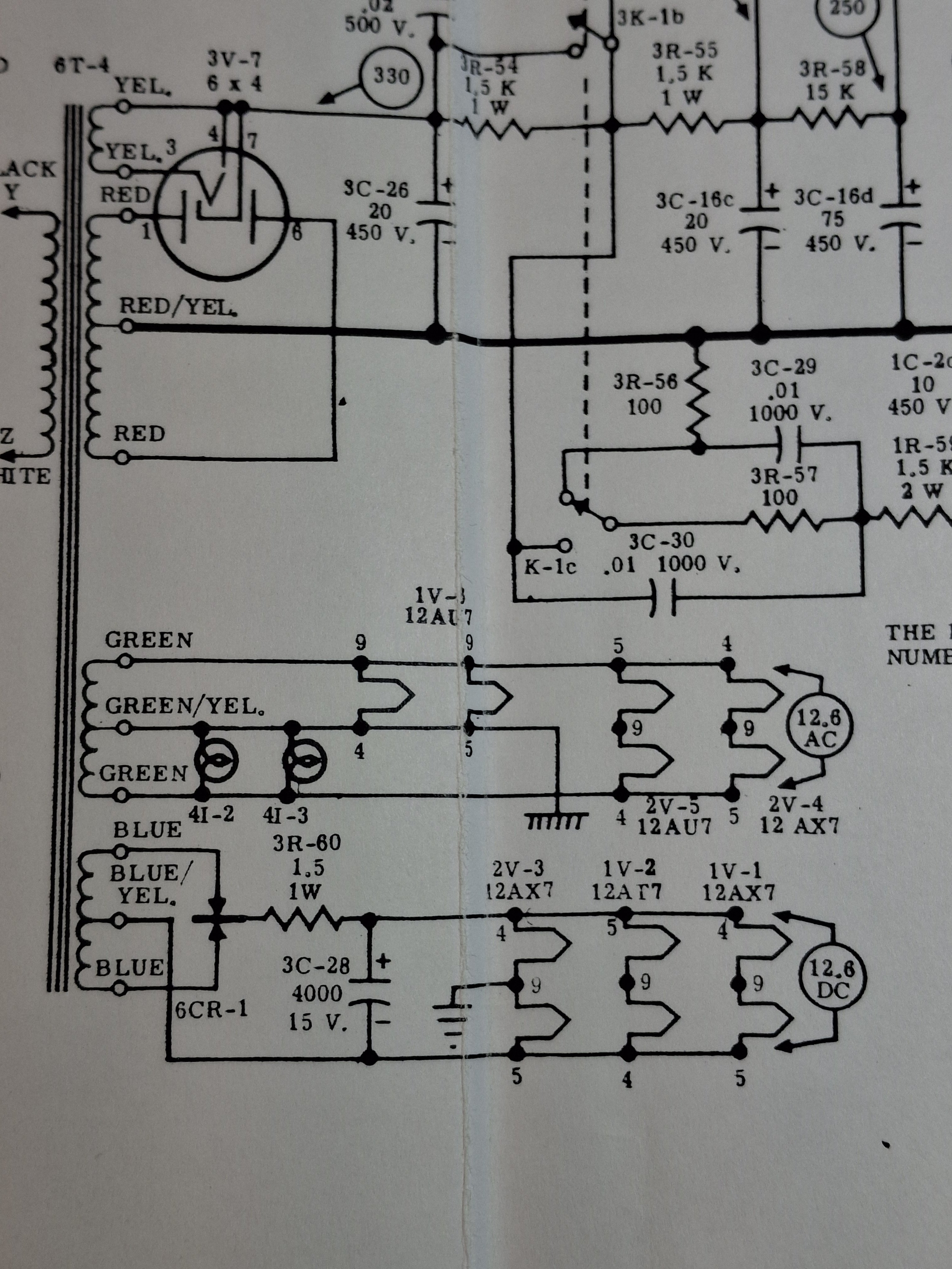
To compensate for this 3R-60 will have to be increased to give the same 12.6vdc to the tubes. Is your unit functioning? If so place a DC voltmeter across 3R-60 and measure the voltage drop across this resistor. Then with the unit switched off remove one leg of 3R-60 and measure its actual resistance. Then take the voltage drop you measured and divide it by the resistance you measured. This will give the amount of the current flow drawn by the tubes. Then go ahead and change out 6CR-1 selenium bridge for your chosen silicon version and replace 3R-60 and measure the DC voltage at the point shown on the schematic. Let me know what you find.
Cheers!
![[Deleted User]](https://w8.vanillicon.com/83b82048d67877ca27bbc25d5d38f9d3_100.png)