Handy guide to the "proper" juxtaposition of inductors in crossovers
Options

mhardy6647
Posts: 35,458
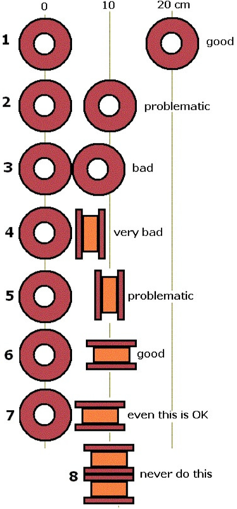
Saw this uploaded to Flikr & thought it was a simple and handy guide for anyone who's wondering about how to arrange inductors in a circuit to minimize any deleterious cross-coupling between inductors. ")
source: https://flic.kr/p/Mo3DfH
source: https://flic.kr/p/Mo3DfH
Comments
-
Good post Mark. I saw someone's crossover upgrade recently that could have used that info.Political Correctness'.........defined
"A doctrine fostered by a delusional, illogical minority and rabidly promoted by an unscrupulous mainstream media, which holds forth the proposition that it is entirely possible to pick up a t-u-r-d by the clean end."
President of Club Polk -
@mhardy6647 Thanks for sharing that.
So does this put the setup for some of our inductors in the "very bad" category? Or does the plastic framework reduce this cross-coupling?
Web pic of 2.3TL factory inductor layout.
-
Any normal plastic should be invisibile to the electromagnetic fields around the inductors. Those two are at right angles, which is good -- their physical proximity is less good, but we're still not lookin' at a worst case scenario -- so all is probably fine.
-
mhardy6647 wrote: »Any normal plastic should be invisibile to the electromagnetic fields around the inductors. Those two are at right angles, which is good -- their physical proximity is less good, but we're still not lookin' at a worst case scenario -- so all is probably fine.
Unless I am seeing it wrong it looks like number 4.............Very bad and worse case scenario -
That is proper placement, no worries
That placement is not even on the chart and it is fine- Not Tom ::::::: Any system can play Diana Krall. Only the best can play Limp Bizkit. -
That placement is not even on the chart and it is fine
Unless I'm seeing incorrectly...looks just like fig 4 when rotated 90 deg.
-
Some info from Pat McGinty (the "Meadolark" guy) on empirically testing for inductive coupling here:
http://www.hifihaven.org/index.php?threads/a-little-pictorial-guide-on-the-juxtaposition-of-inductors-in-a-crossover-for-diy-or-refreshing.4024/#post-76833
The problem with the juxtaposition shown in the photo a few posts back is the physical proximity of the coils. It's certainly not optimal, but it is probably, empirically, fine.
-
My experience with measuring inductors says that it makes such a small difference that it won't matter- Not Tom ::::::: Any system can play Diana Krall. Only the best can play Limp Bizkit.
-
I've found 2, 3 and 8 to be the worst- Not Tom ::::::: Any system can play Diana Krall. Only the best can play Limp Bizkit.
-
No, not like #4. His 2 are sitting on edge, neither is sitting flat.Source: Bluesound Node 2i - Preamp/DAC: Benchmark DAC2 DX - Amp: Parasound Halo A21 - Speakers: MartinLogan Motion 60XTi - Shop Rig: Yamaha A-S501 Integrated - Source: Rotel CD14MkII CD Player - Speakers: Elac Debut 2.0 B5.2
-
For the record, I'm not doubting how well the crossovers work, and they do with the orientation in my pic..just comparing to the diagram.No, not like #4. His 2 are sitting on edge, neither is sitting flat.
What if we take the pic and rotate 90 deg, then instead of looking at the top, imagine looking at the side...nearest the bottom of this pic.
-
The point is, they are 90* orientation from each other which helps reduce the inductive interference.
Greater distance = OK solution
90* = better solution
90* + greater distance = best solution
egg-zack-a-tack-ly.
-
The point is, they are 90* orientation from each other which helps reduce the inductive interference.
Greater distance = OK solution
90* = better solution
90* + greater distance = best solution
I agree.
This is also 90 deg. I want to say that #4 is not referring to this, but the 1st pic.
And again, just curious if either way will make a larger difference, especially in our crossovers.
I'm not complaining....speakers sound great.")
-
as a truism -- a little more space between inductors is better if circumstances permit. I like to give my DIY XOs room to breathe In fact -- why put 'em in the box at all? No real value added (especially if one wishes to... umm... experiment.
-
Interesting lesson professor. I found this. Right hand rule. Explains why the orientation and 90 angles can be placed closer together.

Basement: Polk SDA SRS 1.2tl's, Cary SLP-05 Pre with ultimate upgrade,McIntosh MCD301 CD/SACD player, Northstar Designs Excelsio DAC, Cambridge 851N streamer, McIntosh MC300 Amp, Silnote Morpheus Ref2, Series2 Digital Cables, Silnote Morpheus Ref2 Series2 XLR's, Furman 15PFi Power Conditioner, Pangea Power Cables, MIT Shotgun S3 IC's, MIT Shotgun S1 Bi-Wire speaker cables
Office: PC, EAR Acute CD Player, EAR 834L Pre, Northstar Designs Intenso DAC, Antique Sound Labs AV8 Monoblocks, Denon UDR-F10 Cassette, Acoustic Technologies Classic FR Speakers, SVS SB12 Plus sub, MIT AVt2 speaker cables, IFI Purifier2, AQ Cinnamon USB cable, Groneberg Quatro Reference IC's
Spare Room: Dayens Ampino Integrated Amp, Tjoeb 99 tube CD player (modified Marantz CD-38), Analysis Plus Oval 9's, Zu Jumpers, AudioEngine B1 Streamer, Klipsch RB-61 v2, SVS PB1000 sub, Blue Jeans RCA IC's, Shunyata Hydra 8 Power Conditioner
Living Room: Peachtree Nova Integrated, Cambridge CXN v2 Streamer, Rotel RCD-1072 CD player, Furman 15PFi Power Conditioner, Polk RT265 In Wall Speakers, Polk DSW Pro 660wi sub
Garage #1: Cambridge Audio 640A Integrated Amp, Project Box-E BT Streamer, Polk Tsi200 Bookies, Douglas Speaker Cables, Shunyata Power Conditioner
Garage #2: Cambridge Audio EVO150 Integrated Amplifier, Polk L200's, Analysis Plus Silver Oval 2 Speaker Cables, IC's TBD. -
Interesting lesson professor. I found this. Right hand rule. Explains why the orientation and 90 angles can be placed closer together.
What is this about again? -
All of the inductor photos are the same as what is shown in figure 4. And if the table is correct it is the worse setup. It doesn't matter if the inductors are placed flat side by side, tilted side by side or even on top of each other on a board. The only thing that matters is the orientation of the copper windings. It is number 4.
You can se it easier if you put your pointer finger on each hand thru the hole in each inductor. Your fingers will be pointing in a T. No other orientation in the table will do that.
But is this table correct?
-
My experience with measuring inductors says that it makes such a small difference that it won't matter
Do you take the measurement when BOTH inductors are hooked up, charged and have a current? Testing one inductor at a time won't show much of an effect. And if the neighboring inductor is not hooked up to anything it will have zero effect (no circuit for the coil to do anything). But when both inductors are charged and acting like a magnet thats when you will have a big effect.
-
I just want to eat doughnuts.
-
I just want to eat doughnuts.
Put a doughnut on each pointer finger, look at the chart, play around a little, then eat them!
If you still don't see it get the next two doughnuts............... -
Put a doughnut on each pointer finger, look at the chart, play around a little, then eat them!
If you still don't see it get the next two doughnuts...............
Or maybe an electrolytic cannoli? -
The point is, they are 90* orientation from each other which helps reduce the inductive interference.
Greater distance = OK solution
90* = better solution
90* + greater distance = best solution
I agree.
This is also 90 deg. I want to say that #4 is not referring to this, but the 1st pic.
And again, just curious if either way will make a larger difference, especially in our crossovers.
I'm not complaining....speakers sound great.
That is the same as #4 because the coils are going in the same direction. That is, if you stood up the one laying down it would be parallel to the one on end. Now, if the one laying down was stood up on end and turned 90 degrees that would be good.Political Correctness'.........defined
"A doctrine fostered by a delusional, illogical minority and rabidly promoted by an unscrupulous mainstream media, which holds forth the proposition that it is entirely possible to pick up a t-u-r-d by the clean end."
President of Club Polk -
All of the inductor photos are the same as what is shown in figure 4. And if the table is correct it is the worse setup. It doesn't matter if the inductors are placed flat side by side, tilted side by side or even on top of each other on a board. The only thing that matters is the orientation of the copper windings. It is number 4.
You can se it easier if you put your pointer finger on each hand thru the hole in each inductor. Your fingers will be pointing in a T. No other orientation in the table will do that.
But is this table correct?
In gmcman's photo the coils are in a "T" configuration, which is ok.Political Correctness'.........defined
"A doctrine fostered by a delusional, illogical minority and rabidly promoted by an unscrupulous mainstream media, which holds forth the proposition that it is entirely possible to pick up a t-u-r-d by the clean end."
President of Club Polk -
gmcman's picture is "none of the above" when looking at the original diagrams. The SDA inductors are placed like this:

Jay
SDA 2BTL * McCormack DNA 0.5 amp * Oppo BDP-93 * Modded Adcom GDA-600 DAC * Rythmik F8 (x2)
Micro Seiki DQ-50 * Mitsubishi LT-30 * Hagerman Cornet 2 Phono
Preamp rotation: Krell KSL (SCompRacer recapped) * Manley Shrimp * PS Audio 5.0 -
Lets just say this is not a handy guide. It is either wrong with number 4 being very bad or that a lot of people can't understand the difference between number 4 and number 6.
-
I've been up all night testing these various examples and I still haven't been able to sew the ripped 3/4 sleeve of my Captain and Tennille baseball shirt. :'(

-
Lets just say this is not a handy guide. It is either wrong with number 4 being very bad or that a lot of people can't understand the difference between number 4 and number 6.
Care to illuminate us as to who comprises "a lot of people?"Jay
SDA 2BTL * McCormack DNA 0.5 amp * Oppo BDP-93 * Modded Adcom GDA-600 DAC * Rythmik F8 (x2)
Micro Seiki DQ-50 * Mitsubishi LT-30 * Hagerman Cornet 2 Phono
Preamp rotation: Krell KSL (SCompRacer recapped) * Manley Shrimp * PS Audio 5.0 -
...I'll follow up my previous diagram with this one, which I posit is the same as number 4 (and different from the first one I posted). In essence an "L" instead of a "T".

Not an electrical engineer nor a crossover designer, so I can't wax poetic as to why/how these are different, but my visual-spatial skills tell me there's a difference.Jay
SDA 2BTL * McCormack DNA 0.5 amp * Oppo BDP-93 * Modded Adcom GDA-600 DAC * Rythmik F8 (x2)
Micro Seiki DQ-50 * Mitsubishi LT-30 * Hagerman Cornet 2 Phono
Preamp rotation: Krell KSL (SCompRacer recapped) * Manley Shrimp * PS Audio 5.0 -
What is "bad" might be somewhat nebulous, but this document agrees that arrangements 6 & 7 are "good".Jay
SDA 2BTL * McCormack DNA 0.5 amp * Oppo BDP-93 * Modded Adcom GDA-600 DAC * Rythmik F8 (x2)
Micro Seiki DQ-50 * Mitsubishi LT-30 * Hagerman Cornet 2 Phono
Preamp rotation: Krell KSL (SCompRacer recapped) * Manley Shrimp * PS Audio 5.0 -
so... listen... I would still argue the JPG's handy in that it is small and has a lot of info on it. As to how accurate it may (or may not be) -- note that I did put "proper" in double quotes, folks!
Just think before you stack inductors, 'K?
And avoid them iron/ferrite/etc. core jobbies like the plague.
sheesh, tough crowd. I'm tellin' ya...
")


