My First Douglas Connection DIY Kits - Cable Building Solder Question

msg
Posts: 10,472
Hey guys, just ordered some cable building materials for speaker cables and IC's from the very excellent Mr. Doug himself. What a fantastic experience so far in working with Doug. I've read great reviews and testimonials over the past year, all highly recommending Douglas Connection. None - mine included - can really do justice to the level of service you will experience in working with Doug. It's been absolute top notch so far, every step of the way. Doug is extremely friendly, responsive, and unexpectedly and pleasantly (thankfully) forthcoming with information to ensure a successful DIY build. Really, I thought I'd be completely on my own in the build stage by ordering a DIY kit, which was fair, and I was willing to accept that, but imagine my surprise when I received by email sets of instructions and techniques and tips for getting my cables built. I could probably have muddled through it - horribly - but I'd have messed up a bunch of stuff, for sure. Even with good instructions this is still hard!!!
This is my first cable building project, and I'm not a great solderer, so when all my stuff arrived (fast shipping, I might add) I thought to myself, WOOHOO!!! Look at all this cool audio making stuff!!! This quickly subsided to a slighly lesser excitement at the realization that I had to figure out how to make all this stuff into cables.
(Speaker Cable Kit Pictured)


Even now that I'm into it a bit with some great instructions at my side, and it seems like I'm getting the hang of a few things, it's still a little nerve racking, and I have to say, I very quickly learned the utmost respect for Doug and the custom cable builders. Cable building really seems simple enough when you first think about it, but there's a good bit of stuff one can screw up in cable building, so it takes quite the combination of knowledge, EXPERIENCE, art and technique to get these designs together. I have none of these at the moment and am just doing my best to get a clean end result and not have any cold solder joints where soldering is required. There are a few tips for steps that I simply would not have known to take had I not received instructions. I think it's really cool that Doug offers his designs and build info as DIY projects complete with instructions for those who want turn-key kits. Trust me when I say, if you do buy directly from Doug, and you opt for the custom ready-made cables, you are getting your money's worth. I think I spent at least 8 hours messing around yesterday and only got 2 IC's out of it. (They do work, in case you're wondering. I'm running today on the 4.x hours of sleep I got last night, because I was up past 2am last night enjoying music on them across the Onix, in fact. It was one of those "... and I wonder what this sounds like..." sessions, where I just kept listening to all kinds of different stuff. Initial impressions, pretty smooth sweet response. I'll get a proper review together when I get all the cables together)
==============================
So I'm on my way here with these builds, but thought I'd throw up this question. I'd be asking Doug himself - tremendously patient, friendly and helpful - but don't want to bug him on the weekend.
I'm using Cardas quad eutectic, and a WES51 iron, both recommended by a trusted member. I couldn't solder for crap for years. a nice iron/tip and some good solder (Kester works well, too, but I went with the recommended Cardas for my audio connectors) make a game changing combination. I'm actually getting the hang of it, and haven't even burned myself yet.
Okay, so I've got a couple of these IC's made already, and I soldered to the solder band, but not sure exactly how this is supposed to work. is one supposed to solder through this gap? or is the gap just there creating the band to make for easier heating and soldering of the band for proper joint, as opposed to trying to heat the sleeve itself and possibly resulting in a cold solder joint? The first connector was a complete hack job. it's a strong bond. I know this because the wires were sticking up and I couldn't thread the sleeve over and had to bend and then snip the excess. It was laughably sloppy at first, but I managed to neaten it up and get it working. they got progressively better. I've soldered to the band itself, and not filled solder in this gap there between the band and body. Is this correct?
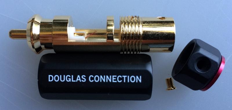
and how about on this Vampire connector? this is going to be for a digital coax. I'm to solder the core to the inside sleeve there. should I tin the core, and then add some solder to the sleeve, and then try to heat the sleeve/wire while sliding the wire in? or do I fill the sleeve, and then heat it from the pin side while fitting the wire? This is kind of hard to describe.

I'll post up with some more photos of the progress and finished cables as move through the builds. Some of them will be hacky and embarrassing but screw it, I'll post them anyway. I'm determined to learn how to do this with some measure of quality, so feel free to post up comments and suggestions. Corrections, even")
This is my first cable building project, and I'm not a great solderer, so when all my stuff arrived (fast shipping, I might add) I thought to myself, WOOHOO!!! Look at all this cool audio making stuff!!! This quickly subsided to a slighly lesser excitement at the realization that I had to figure out how to make all this stuff into cables.
(Speaker Cable Kit Pictured)
Even now that I'm into it a bit with some great instructions at my side, and it seems like I'm getting the hang of a few things, it's still a little nerve racking, and I have to say, I very quickly learned the utmost respect for Doug and the custom cable builders. Cable building really seems simple enough when you first think about it, but there's a good bit of stuff one can screw up in cable building, so it takes quite the combination of knowledge, EXPERIENCE, art and technique to get these designs together. I have none of these at the moment and am just doing my best to get a clean end result and not have any cold solder joints where soldering is required. There are a few tips for steps that I simply would not have known to take had I not received instructions. I think it's really cool that Doug offers his designs and build info as DIY projects complete with instructions for those who want turn-key kits. Trust me when I say, if you do buy directly from Doug, and you opt for the custom ready-made cables, you are getting your money's worth. I think I spent at least 8 hours messing around yesterday and only got 2 IC's out of it. (They do work, in case you're wondering. I'm running today on the 4.x hours of sleep I got last night, because I was up past 2am last night enjoying music on them across the Onix, in fact. It was one of those "... and I wonder what this sounds like..." sessions, where I just kept listening to all kinds of different stuff. Initial impressions, pretty smooth sweet response. I'll get a proper review together when I get all the cables together)
==============================
So I'm on my way here with these builds, but thought I'd throw up this question. I'd be asking Doug himself - tremendously patient, friendly and helpful - but don't want to bug him on the weekend.
I'm using Cardas quad eutectic, and a WES51 iron, both recommended by a trusted member. I couldn't solder for crap for years. a nice iron/tip and some good solder (Kester works well, too, but I went with the recommended Cardas for my audio connectors) make a game changing combination. I'm actually getting the hang of it, and haven't even burned myself yet.
Okay, so I've got a couple of these IC's made already, and I soldered to the solder band, but not sure exactly how this is supposed to work. is one supposed to solder through this gap? or is the gap just there creating the band to make for easier heating and soldering of the band for proper joint, as opposed to trying to heat the sleeve itself and possibly resulting in a cold solder joint? The first connector was a complete hack job. it's a strong bond. I know this because the wires were sticking up and I couldn't thread the sleeve over and had to bend and then snip the excess. It was laughably sloppy at first, but I managed to neaten it up and get it working. they got progressively better. I've soldered to the band itself, and not filled solder in this gap there between the band and body. Is this correct?
and how about on this Vampire connector? this is going to be for a digital coax. I'm to solder the core to the inside sleeve there. should I tin the core, and then add some solder to the sleeve, and then try to heat the sleeve/wire while sliding the wire in? or do I fill the sleeve, and then heat it from the pin side while fitting the wire? This is kind of hard to describe.
I'll post up with some more photos of the progress and finished cables as move through the builds. Some of them will be hacky and embarrassing but screw it, I'll post them anyway. I'm determined to learn how to do this with some measure of quality, so feel free to post up comments and suggestions. Corrections, even
I disabled signatures.
Comments
-
The Vampire site has instructions with amount to cut/strip. If dimensions are not adhered to, particularly with braid, by tightening the compression nut you can cause excess strain on soldered center conductor which can cause it to stretch/break, creating an open. Seen that happen before.
"For 5-5.7mm dia. cables. Uses compression to insure proper RF shielding and strain relief. Slide nut on cable. Strip 3/4” of jacket, cut shield to 1/4”, strip tip 1/2” of center conductor, fold shield back on jacket. Place compression collar over shield, solder center conductor to center pin, slide on ground crown, tighten outer barrel."
I like to tin (thin coat of solder) the wires I solder. Once inserted into RCA pin, apply heat below opening in RCA pin (opening just beyond insulator). See pic below) Feed solder in as it melts. You don't want solder on outside of RCA pin that extends into connectors on your gear. You don't have to fill that entire RCA pin with solder for a good joint. Even though insulator is durable, I like to get in and out as quick as possible while insuring a good joint. I don't like to overheat solder joints.")
Not exact same connector, but it shows slot in RC pin where to solder. If you put tip of iron in hole and apply solder to iron, your solder will melt quickly but if pin/wire not hot enough, you'll get a poor joint. If the tip is small enough, you can insert and apply heat to one side of hole and feed solder from other side. Heat draws solder. It all depends on your level of experience and iron you have.
Yes, that narrow band on the RCA in upper pic is a solder point. When you apply heat from your iron, that entire hunk of metal becomes a heat sink, drawing heat away. Not enough heat, you get a poor solder joint.
Wire should be soldered to inside of that ring. (Don't wrap wire around that ring). If your ground is a stiff wire, the bond should be good or moving the RCA around will dislodge a poor solder joint and you'll get a hummmmmmmmmmmmm.
Not my pic, snagged from internet. You can see they used coax and soldered braid to slotted ring. They might have even used a large wattage soldering gun that will apply a lot of heat quickly to that small area. Post edited by SCompRacer onSalk SoundScape 8's * Audio Research Reference 3 * Bottlehead Eros Phono * Park's Audio Budgie SUT * Krell KSA-250 * Harmonic Technology Pro 9+ * Signature Series Sonore Music Server w/Deux PS * Roon * Gustard R26 DAC / Singxer SU-6 DDC * Heavy Plinth Lenco L75 Idler Drive * AA MG-1 Linear Air Bearing Arm * AT33PTG/II & Denon 103R * Richard Gray 600S * NHT B-12d subs * GIK Acoustic Treatments * Sennheiser HD650 *
 -
ah, I see on the Vampire, I didn't realize the tip could be disassembled further. the one I have looks just like the one you posted. indeed, I did receive instructions from Doug on how much to strip for the cable provided in the kit, similar to what you've provided above. I just wasn't quite sure how to solder the core to the tip, and now I do after learning that it should be disassembled further.
agreed on the tinning - good tip there.
I've found that tinning seems to be the trick to getting in and out quickly with strong shiny joints.
very helpful info, thank you. yes, I was wondering about how to work with the solder band. good point about not wrapping the wire, hehe. it did occur to me. were it not for the locking sleeve, that might have been something I'd do. or fill that gap. neat design idea to get proper joint.I disabled signatures. -
I installed some Vampire coax ends on a Yamaha YP-D10 I had. Good stuff! This was a Siamesed cable (R and L channel cables bonded together). I was either lucky or good as the ends were exactly terminated for length...
 Salk SoundScape 8's * Audio Research Reference 3 * Bottlehead Eros Phono * Park's Audio Budgie SUT * Krell KSA-250 * Harmonic Technology Pro 9+ * Signature Series Sonore Music Server w/Deux PS * Roon * Gustard R26 DAC / Singxer SU-6 DDC * Heavy Plinth Lenco L75 Idler Drive * AA MG-1 Linear Air Bearing Arm * AT33PTG/II & Denon 103R * Richard Gray 600S * NHT B-12d subs * GIK Acoustic Treatments * Sennheiser HD650 *
 -
haha, cool!
yeah, I want to add new connections to everything I have that has garbage wires on them now!
so this originally had a single plug?I disabled signatures. -
The Yamaha had them cheap plated RCA's. There was just a thin rib of material holding the two lengths of coax together. The ground wire was attached also. Kept it neater to route.
Doug has supplied me with material for power cables. High marks for your DIY approach!
Salk SoundScape 8's * Audio Research Reference 3 * Bottlehead Eros Phono * Park's Audio Budgie SUT * Krell KSA-250 * Harmonic Technology Pro 9+ * Signature Series Sonore Music Server w/Deux PS * Roon * Gustard R26 DAC / Singxer SU-6 DDC * Heavy Plinth Lenco L75 Idler Drive * AA MG-1 Linear Air Bearing Arm * AT33PTG/II & Denon 103R * Richard Gray 600S * NHT B-12d subs * GIK Acoustic Treatments * Sennheiser HD650 * -
some more photos...
Douglas Connection Locking RCA Plug, gold plated brass. These are quite nice to work with. That solder band is a neat idea for heavy brass connectors.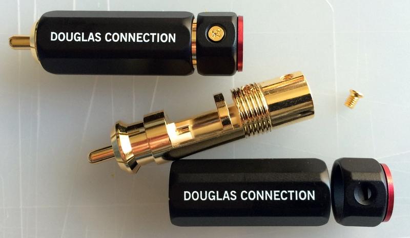
Two Raw Furez FZ162AA Analog Interconnect Cable; one sleeved (not an abandoned snakeskin)
Once I get the cable sleeved, I slide the rest of the connector hardware up onto the center of the cable, and secure out of the way with some tape. This is so I don't solder and then realize I can't get my connector hardware on after the fact! (I've done this with heat shrink more times than I care to admit)
Sleeving slid up onto the cable and secured out of the way temporarily.
Trimming the jacket.
Conductors trimmed, shielding twisted; all ready for tinning
== I do have a question here - I'm not really sure which way the wire is twisted under the conductor insulation, so it's quite possible that I've twisted it in the opposite direction? ==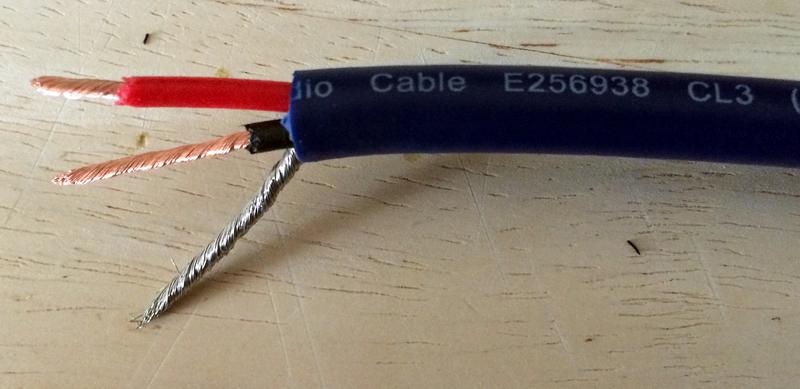
Side Note: All of these photos are from building the "In" side of the cable. This next shot is from a jump to the "Out" side of the cable build. Note the absence of the shielding. Here, we cut off the shielding and stuff it back down inside the jacket a bit. The shielding is terminated on one side only in this design.
Back to the "In" side...
Conductors tinned. Noting the melting insulation where I got a little hot on the tinning. Oops.
Double-sided tape placed to hold sleeving in place (paper still in place). Trying something a little different on this set. On the first set, I had the double-sided tape all the way to the end of the jacket, and even a little over, to try to hold stray sleeving strands down to make it easier to insert into the connector bore, but once you slide the sleeving back down over the end and get it trimmed, it's a little tight getting it inside the connector with the double-sided tape beneath it. Another suggested trick was to use a little teflon plumber's tape to corral the stray sleeving strands that stick out. It can be a little easier with this, but still tighter since there's also double-sided tape underneath. It's a lot to squeeze in there. Doable, but takes some working of the sleeving.
View of soldered connection.
I got a little sloppy on this one, and had to use a little fine emery cloth to remove the solder I wasn't able to smooth/remove with heat (It's important to not get solder on the outside of the connector, because it can interfere with the locking barrel action) It may be detrimental doing this as I may have exposed some of the base brass, possibly removing some of the plating.
I don't have a photo of it, but one of the things I read in Doug's instructions was to make sure you get the conductors pressed against the solder band. I just wedged a small flat blade screwdriver in there to push them against, the heated the band and fed some solder. That Cardas is really nice stuff, and I've been very pleased with the WES51. I couldn't solder for crap before. (Now at least I can solder for crap. I think.)
== Any better ways to remove stuff like this? I have a couple of bobo solder suckers, but it seemed too fine an amount of over-solder for that to work. Solder wick? ==
Again, I like that solder band on the body. I've pressed pretty hard on the the tips of the conductors after soldering, as sometimes I have to bend them down a little bit so they don't interfere with the barrel. It's on there - gutentite! Then I nip the ends off for neatness.
Connector with soldered conductors.
After the emery cloth treatment and ready to be buttoned up.
Getting ready to thread down the lock barrel and fasten the lock nut.
Finished Connector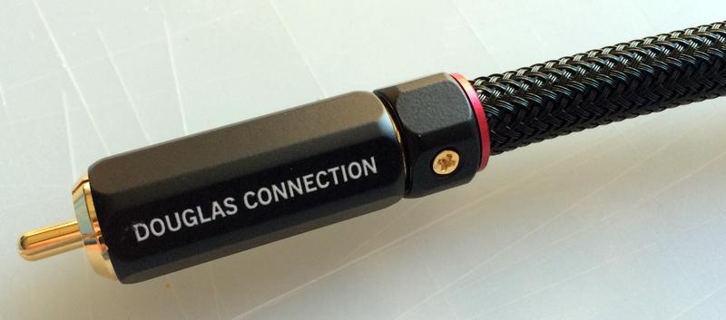
Finished DIY Douglas Connection Design Analog IC, hacked by msg!
All in all, I really like these so far! though I feel like I'd like the connector to lock a smidge tighter. It's not going to come off from a casual reposition of the equipment, but you can still twist it off in the locked position with a little work. I think you'd be hard pressed to beat these connectors, and even the cable overall, in this price range. Very, very pleased with these. Many thanks Doug!
Speaker cables and digital coax up next this week or next.
Depending on when my fingers stop hurting.
Now, to go squeeze in a little listening time... Post edited by msg onI disabled signatures.
 -
Thanks!SCompRacer wrote: »The Yamaha had them cheap plated RCA's. There was just a thin rib of material holding the two lengths of coax together. The ground wire was attached also. Kept it neater to route.
Doug has supplied me with material for power cables. High marks for your DIY approach!
And I'd like to try these power cables next, myself!
Have you started them yet?
Funny to think that four months ago I was a cable skeptic...I disabled signatures. -
Nice professional looking IC's!
== I do have a question here - I'm not really sure which way the wire is twisted under the conductor insulation, so it's quite possible that I've twisted it in the opposite direction? ==
== Any better ways to remove stuff like this? I have a couple of bobo solder suckers, but it seemed too fine an amount of over-solder for that to work. Solder wick? ==
If wire starts to unravel when twisting, then reverse the twist direction. Usually you can tell by looking at the strand orientation.
Emery cloth, sand paper, small file are ways to remove excess solder from that ring so you can thread the barrel on. Reheating and wiping can disturb the joint.
One helpful thing with soldering is apply solder 180 degrees opposite of where the iron is placed. Like iron against one side of slotted ring, apply solder on the opposite side of ring. Iron against one side of RCA pin, apply solder to opposite side against wire. This applies to boards, point to point, etc. Heat draws solder and it will melt and pull into the joint. Once it flows and you have a good build up, you can remove solder and then remove heat. There are videos on youtube to help you out.
Solder suckers are a handy thing to have around. Spring loaded with trigger. You **** it, get the joint hot and press the button. They won't work the best on rounded surfaces like RCA's but they will remove quite a bit of solder.
You can get them in various sizes. You can also buy powered solder sucker guns but they are pricey. Real handy when re-capping amps or pre amps though.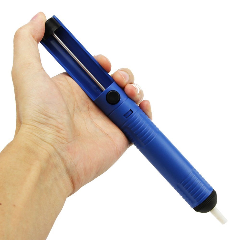
My two twenty amp outlets are near a corner of room. My amp is between speakers a few feet away. I needed a nice heavy duty power strip and wiring for amp and my two subs. I got the wire, plugs (including IEC) and outlets from Doug. The aluminum box with IEC cutout I found on ebay.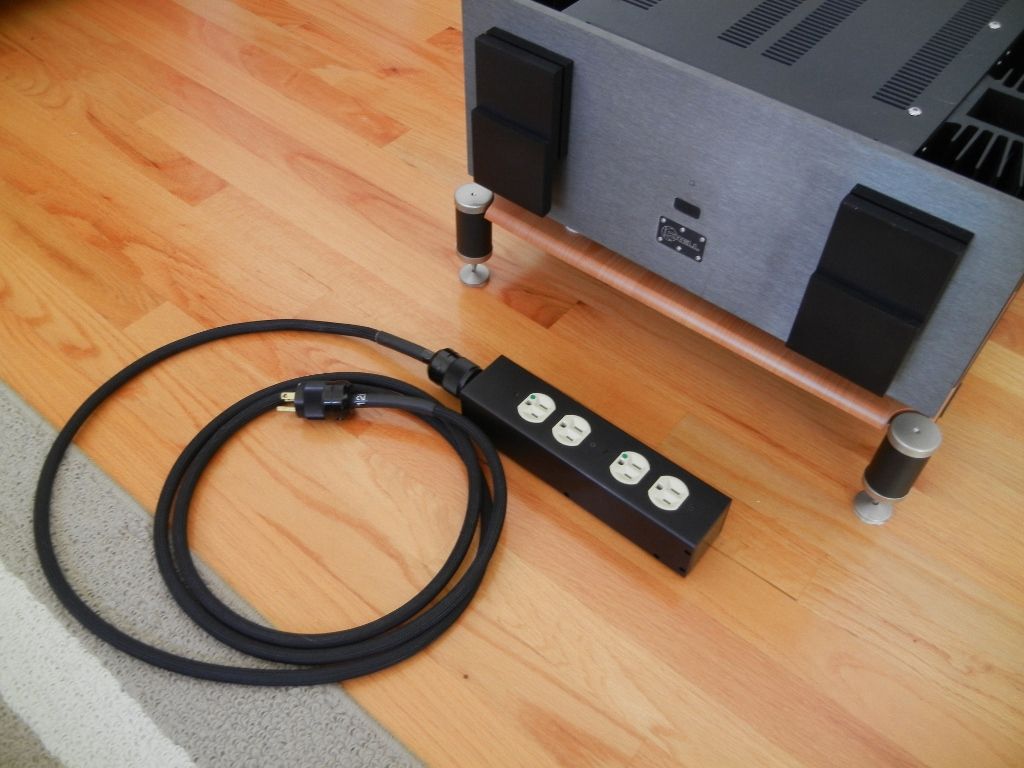 Salk SoundScape 8's * Audio Research Reference 3 * Bottlehead Eros Phono * Park's Audio Budgie SUT * Krell KSA-250 * Harmonic Technology Pro 9+ * Signature Series Sonore Music Server w/Deux PS * Roon * Gustard R26 DAC / Singxer SU-6 DDC * Heavy Plinth Lenco L75 Idler Drive * AA MG-1 Linear Air Bearing Arm * AT33PTG/II & Denon 103R * Richard Gray 600S * NHT B-12d subs * GIK Acoustic Treatments * Sennheiser HD650 *
 -
Thanks! This is fun stuff.SCompRacer wrote: »Nice professional looking IC's!
If wire starts to unravel when twisting, then reverse the twist direction. Usually you can tell by looking at the strand orientation.== I do have a question here - I'm not really sure which way the wire is twisted under the conductor insulation, so it's quite possible that I've twisted it in the opposite direction? ==
== Any better ways to remove stuff like this? I have a couple of bobo solder suckers, but it seemed too fine an amount of over-solder for that to work. Solder wick? ==
Emery cloth, sand paper, small file are ways to remove excess solder from that ring so you can thread the barrel on. Reheating and wiping can disturb the joint.
One helpful thing with soldering is apply solder 180 degrees opposite of where the iron is placed. Like iron against one side of slotted ring, apply solder on the opposite side of ring. Iron against one side of RCA pin, apply solder to opposite side against wire. This applies to boards, point to point, etc. Heat draws solder and it will melt and pull into the joint. Once it flows and you have a good build up, you can remove solder and then remove heat. There are videos on youtube to help you out.
Okay that makes sense on the wire unraveling. That didn't happen so pretty sure it's twisted correctly.
Ah man, that's a great soldering tip, the 180 degree thing. I wouldn't have known to do that. I'll try that on the next IC. That makes sense, but I didn't know heat drew solder. Same thing for tinning the wires too? I've been sort of angling the wires downward, and then adding some solder to the tip, and beginning near the insulation, running the iron and solder down and off the wire? With using two hands, I guess that 180 thing just sort of happens.
Thanks for the tips on removal. I have a similar solder sucker and I did notice, like you mentioned, that it didn't work as well on the curved surface as a small bulb one worked on a flat, board project the last time I tried one. I thought I remembered reading something a while back where a member mentioned filing the nozzle of the SS for better mating to a solder joint?
And also good info on not reheating to remove solder so as not to disturb the joint. See, that's something I'd have learned the hard way, so these are helpful tips, thanks.
fantastic power strip! very clean.My two twenty amp outlets are near a corner of room. My amp is between speakers a few feet away. I needed a nice heavy duty power strip and wiring for amp and my two subs. I got the wire, plugs (including IEC) and outlets from Doug. The aluminum box with IEC cutout I found on ebay.
I don't know enough about power to know how that should be wired up inside the box. Parallel? From my circuits class, about all I remember is "SSC" - series same current, so parallel same voltage?
That cable looks pretty stout. Which "model" was that that you built? I think I was looking at Select or Elite 12.
Have you detailed this power strip build? I'd be interested to see how you made this, wiring, outlets used, etc.
I can see this DIY stuff becoming addicting. I'm finding it very rewarding so far.I disabled signatures. -
That makes sense, but I didn't know heat drew solder. Same thing for tinning the wires too?
Yes. A little solder on the iron tip helps to conduct heat into the wire/joint. If you apply solder directly to hot iron, it will melt and flow, but you may not get a good solid joint if the work isn't hot enough. If the work melts solder, you know it's hot enough. I love Cardas Quad Eutectic. If you ever get into modding gear, RoHS gear uses lead free solder and it is harder to remove.I thought I remembered reading something a while back where a member mentioned filing the nozzle of the SS for better mating to a solder joint?
Might be me I did that and mentioned it here. A small round file conformed the sucker tip around iron tip. Some suckers do have replacement tips available.And also good info on not reheating to remove solder so as not to disturb the joint. See, that's something I'd have learned the hard way, so these are helpful tips, thanks.
If I have to re-do, I'll remove and resolder. If you just want to resolder a joint, have some flux around (not acid core of course, rosin core).fantastic power strip! very clean.
I don't know enough about power to know how that should be wired up inside the box. Parallel? From my circuits class, about all I remember is "SSC" - series same current, so parallel same voltage?
That cable looks pretty stout. Which "model" was that that you built? I think I was looking at Select or Elite 12.
Have you detailed this power strip build? I'd be interested to see how you made this, wiring, outlets used, etc.
Thanks! Both outlets wired in parallel off the IEC. I don't have inside pics. It is 12/3 wire with Doug's hospital grade outlets. That amp pulls around 10 amps at idle and it has never choked when asked to deliver hearing loss sound levels through the extension/power strip. The anodized aluminum box was from China. They sold them in various outlet configurations and in natural aluminum or black.
DIY can look good, work without problems and allow you to reach past your budget for retail items.Salk SoundScape 8's * Audio Research Reference 3 * Bottlehead Eros Phono * Park's Audio Budgie SUT * Krell KSA-250 * Harmonic Technology Pro 9+ * Signature Series Sonore Music Server w/Deux PS * Roon * Gustard R26 DAC / Singxer SU-6 DDC * Heavy Plinth Lenco L75 Idler Drive * AA MG-1 Linear Air Bearing Arm * AT33PTG/II & Denon 103R * Richard Gray 600S * NHT B-12d subs * GIK Acoustic Treatments * Sennheiser HD650 * -
Very very nice. I think I would surely screw it up.
Maybe I should look online in the future for by cables
By MSG. 
Because I am The Pumpkinking
A Kind Word Is An Easy Gift To Give -
haha, maaaaan, at the rate of two IC's per day, I'd bankrupt myself at best! -- I'll leave it to the pros like Dougpumpkinman wrote: »Very very nice. I think I would surely screw it up.
Maybe I should look online in the future for by cables
By MSG.
and thanks. this is fun stuff! you might be surprised at the result if you give it a shot. Doug's kits take a lot of the runaround and guesswork out of the design.
Woh, 10A at idle?!? which amp is that?SCompRacer wrote: »Thanks! Both outlets wired in parallel off the IEC. I don't have inside pics. It is 12/3 wire with Doug's hospital grade outlets. That amp pulls around 10 amps at idle and it has never choked when asked to deliver hearing loss sound levels through the extension/power strip. The anodized aluminum box was from China. They sold them in various outlet configurations and in natural aluminum or black.
DIY can look good, work without problems and allow you to reach past your budget for retail items.
I might give something like this a shot for places where I need good clean extension. That seems like a great idea. Now if I can just line up my electrician friend for a 20A...I disabled signatures. -
Nice job Scott! Looks like you caught on quickly as those IC's are looking really nice Bother!
And this is a great Thread you got going and it helps others see how it is done as you did a nice job documenting it!
And Rich's help is always excellent!
2 ch- Polk CRS+ * Vincent SA-31MK Preamp * Vincent Sp-331 Amp * Marantz SA8005 SACD * Project Xperience Classic TT * Sumiko Blue Point #2 MC cartridge
HT - Polk 703's * NAD T-758 * Adcom 5503 * Oppo 103 * Samsung 60" series 8 LCD -
Hey, thanks a lot Darryl!
I was inspired by your DIY SC's, man!
Indeed, great tips there from SCR! - answered all my questions!
I think I'm becoming obsessed. I keep thinking about what else I can cable and solder, haha
This has been a lot of fun so far. Doug said the DIY route could be tremendously rewarding, and he's right.
I'm excited to get the set of the digital coax, IC's and SC's completed, get them on a system and burned in, and to see how they all sound together. PC's would be nice, too; maybe later.I disabled signatures. -
Glad you are having so much fun Scott! Looking very nice! Thanks for doing this thread. It's a good one for guys to refer to when doing DIY interconnects and speaker cables. Sunfire Theater Grand IV
Sunfire Cinema Grand Signature
SRS 2.1TL
SDA 2BTL's
CSiA6
FXiA4
FXiA6
SDA 2A's
Monitor 10A's
http://www.douglasconnection.com -
Woh, 10A at idle?!? which amp is that?
It's an old re-capped Krell KSA-250. 250Wpc into 8 ohms, 500Wpc into 4 ohms, 1kWpc into 2 ohms, 2kWpc into 1 ohm, 4kWpc into 0.5 ohm. It's an amp that never has to say I'm sorry to your speakers demands... Salk SoundScape 8's * Audio Research Reference 3 * Bottlehead Eros Phono * Park's Audio Budgie SUT * Krell KSA-250 * Harmonic Technology Pro 9+ * Signature Series Sonore Music Server w/Deux PS * Roon * Gustard R26 DAC / Singxer SU-6 DDC * Heavy Plinth Lenco L75 Idler Drive * AA MG-1 Linear Air Bearing Arm * AT33PTG/II & Denon 103R * Richard Gray 600S * NHT B-12d subs * GIK Acoustic Treatments * Sennheiser HD650 * -
-
SCompRacer wrote: »
Just wow, that's awesome power.Pio Elete Pro 520
Panamax 5400-EX
Sunfire TGP 5
Micro Seiki DD-40 - Lyra-Dorian and Denon DL-160
PS Audio GCPH phono pre
Sunfire CG 200 X 5
Sunfire CG Sig 405 X 5
OPPO BDP-83 SE
SDA SRS 1.2TL Sonicaps and Mills
Ctr CS1000p
Sur - FX1000 x 4
SUB - SVS PB2-Plus
Workkout room:
Sony Bravia XBR- 32-Inch 1080p
Onkyo TX-DS898
GFA 555
Yamaha DVD-S1800BL/SACD
Ft - SDA 1C
Not being used:
RTi 38's -4
RT55i's - 2
RT25i's -2, using other 2 in shop
LSI 15's
CSi40
PSW 404 -
"....not everything that can be counted counts, and not everything that counts can be counted." William Bruce Cameron, Informal Sociology: A Casual Introduction to Sociological Thinking (1963)
-
HT SYSTEM-
Sony 850c 4k
Pioneer elite vhx 21
Sony 4k BRP
SVS SB-2000
Polk Sig. 20's
Polk FX500 surrounds
Cables-
Acoustic zen Satori speaker cables
Acoustic zen Matrix 2 IC's
Wireworld eclipse 7 ic's
Audio metallurgy ga-o digital cable
Kitchen
Sonos zp90
Grant Fidelity tube dac
B&k 1420
lsi 9's -
I think it powers right through that conversation.
Not with my wife it wouldn't. lolHT SYSTEM-
Sony 850c 4k
Pioneer elite vhx 21
Sony 4k BRP
SVS SB-2000
Polk Sig. 20's
Polk FX500 surrounds
Cables-
Acoustic zen Satori speaker cables
Acoustic zen Matrix 2 IC's
Wireworld eclipse 7 ic's
Audio metallurgy ga-o digital cable
Kitchen
Sonos zp90
Grant Fidelity tube dac
B&k 1420
lsi 9's -
Yeah but does it apologize when you get the electric bill ?
Some things are worth the cost. Besides, she has 300 watts of garden lights from the public sidewalk to the back of house, so if she wants them to work.....
Forgot to add we got a variable speed furnace now. Converts AC to DC for motor. That has provided some savings power wise.Salk SoundScape 8's * Audio Research Reference 3 * Bottlehead Eros Phono * Park's Audio Budgie SUT * Krell KSA-250 * Harmonic Technology Pro 9+ * Signature Series Sonore Music Server w/Deux PS * Roon * Gustard R26 DAC / Singxer SU-6 DDC * Heavy Plinth Lenco L75 Idler Drive * AA MG-1 Linear Air Bearing Arm * AT33PTG/II & Denon 103R * Richard Gray 600S * NHT B-12d subs * GIK Acoustic Treatments * Sennheiser HD650 *


