My FrankenPolk... PSW650
I have three Polk PSW650 subwoofers. The amplifier on one of them unfortunately died (which seems common with subwoofers) and I was left with a deadweight with a couple of decent drivers. After contacting Polk, I was dismayed that the amplifier was not repairable and that it was not available anymore. I tried to replace the amplifier with a third party alternative but could not find one that fit because the Power Port vents were too large on the rear panel, limiting the area for the plate amplifier.
During the Christmas holidays, I decided to do something about it. I tore apart the old cabinet, keeping the vent tubes, the Power Ports, the grills and the rubber grommets for the grills. I picked up the Dayton Audio Speaker Analyzer (DATS) and the speaker cabinet software from Parts Express. Unfortunately, the software could not come up with a viable solution for a new design (I was really hoping for an isobaric design). Since I could not come up with a suitable alternative, I decided to rebuild the PSW650. I bought their Dayton SA250 250-watt (into 4-ohms) subwoofer plate amplifier. The original Polk amplifier was 165 watts and I did not want to go overboard and drive the speakers beyond the excursion limits. The speaker themselves were measured at 2-ohms each and were wired in series giving a nominal value of 4-ohms.
To keep the speakers within design specs, I kept the same dimensions...I measured the original cabinet at 16"x17x18" with 1" driver baffles and 3/4" baffles for the other. I bought some 3/4" and 1/2" MDF boards for the build. It was fairly obvious that the layout had to be rearranged. The amplifier was 10"x10"x4", so it occupied the rear panel. That meant the vents had to go somewhere else. Looking at some vintage Polk subwoofers, I decided to mount the vents on the bottom. I designed the cabinet to be 18" deep, 17" wide and 16" deep. I also had to decide how to finish the cabinet. I was thinking of piano gloss black but thought that my skills and tools would not make an even finish so decided on a walnut veneer.
Let me be up front, I am not a carpenter and I did not have the proper tools for the build. I used a circular saw with a old RotoZip and a cheap sander. The side panels were made of two 1/2" panels glued together to make a 1" thick panel. The outer panel was cut with a 10" circle to fit the driver. The inner panel was cut to 9" for the driver to rest on, making it somewhat flush with the outer panel. The RotoZip can cut decent circles but it was very hard to get them the exact size as the tool kept on shifting in diameter. It would have been better to get a decent router and a Jasco circle cutter guide but i wanted to keep expenses to a minimum. The rear 3/4" panel was cut with 8x8" opening and countersunked with a 10"x10" 1/4" area to flush mount the amplifier.
The bottom panel posed a problem. The sub cabinet was 18" long. The two Power Ports were 7"x8". Mounting them next to each other would take 14". The 18" minus the 1.5" for the front and rear panel left me with 16.5" inside. The amplifier had an internal depth of 4". The vent tubes were 3" in diameter but had large flared ends on the inside. I could not get the entire design to fit within the 18" without some compromise. My decision was to trim 1" off the edge of the Power Port. So the side panels were 18" long and 16" wide. The top and bottom panels were 18" long and 15" wide. The front and back panels were 15" by 14.5". The Power Ports were screwed in a bit and I drew a line across the screw holes to find the center point to cut out the vent holes. I then cut the power ports vents in the bottom panel and rounded the edges on the bottom like the original.. I also added two vertical 18" braces to stiffen the cabinet.
I then started assembly. Bit of advice. You really need a good table saw. Even with a good table saw, you cannot cut the wood perfectly. Doing a test fit showed that there was an awful lot of raised joints. I glued and screwed the whole cabinet together. I got out a belt sander and ground down the raised edges but got a bit overly aggressive on the top (there is a slight depression) and under aggressive on the front, but it came out decently.
I had some unused walnut veneer and applied it to the cabinet. I ran the grain from the front, over the top and on the back with one long piece so that the grain matched at the edges. The sides had the grain running vertically. I then sanded the veneer with 180-grit paper, then 220 and finally 320-grit, being careful not to cut through the thin veneer. I applied three coats of oil based Oak stain (I did not want the cabinets to be too dark). After that, I applied three coats of Danish Oil. After that dried, I then wet sanded (with thinned Danish Oil) it with 0000 grade steel wool to even out the luster and applying satin wax over the finish. I then had to drill in the holes for the grill grommets. I was kind of stumped with this for a bit but got an idea. I drew a line horizontally along the top edge of the cutout and repeated it with a vertical line that intersected the horizontal line. I repeated this process at all four corners. I used a long ruler and measured diagonally a 13" (the grill pins were 13" in diameter across the grill) point equidistant (i.e. 1.5" from the circle). I made sure that the marks were all the same distance diagonally as well as adjacently. I used an ice pick for a starter hole and drilled a 3/8" bore to fit the grommets. It came out perfectly.
I stuffed the cabinet with the original filling from the PSW650 and added a bit more of dacron fill. I then screwed the Power Ports into the bottom of the cabinet. The ports had a depth of 1-3/8" so I got a dowel and cut four pieces in that length. I then attached a 17"x18" MDF board on the bottom mounted to the dowels. I then screwed the cabinet to the dowels. I screwed in the drivers, wired the amp in series and screwed the amp in.
I took the sub (which by this time was awfully heavy) into my house and connected it to my system. i was at first sorely disappointed by the weak bass until I realized I had the system playing stereo with no sub signal. I changed it back to 7.1 and got the sub working.
The sub was a bit more powerful than the original and had a bit more dynamic punch. My guess is that it bottoms out at 30-35Hz (like the original). In retrospect, I should have made the cabinet an inch or two larger, because the interior volume is a bit smaller than the original, because of the added vertical braces and that the amp was a bit larger inside the cabinet. I am pretty happy with the end result and must admit the final finish looks really nice.
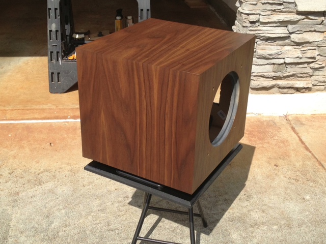
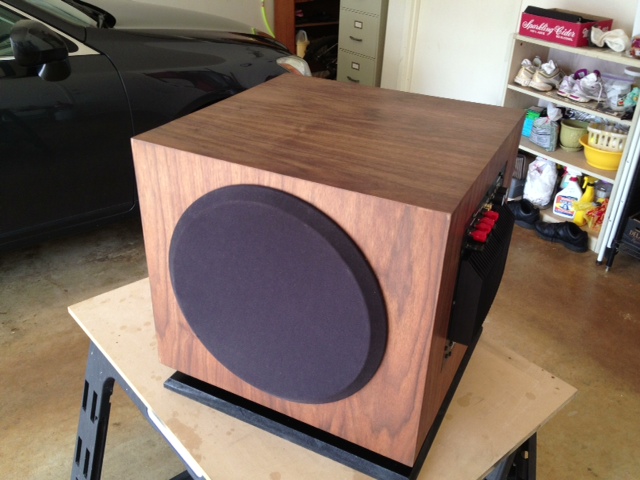
The attached pictures are of the cabinet before staining but after wood conditioner was applied.
Post edited by jon s on
Comments
-
More pictures... These pictures show a more accurate color on the sub...

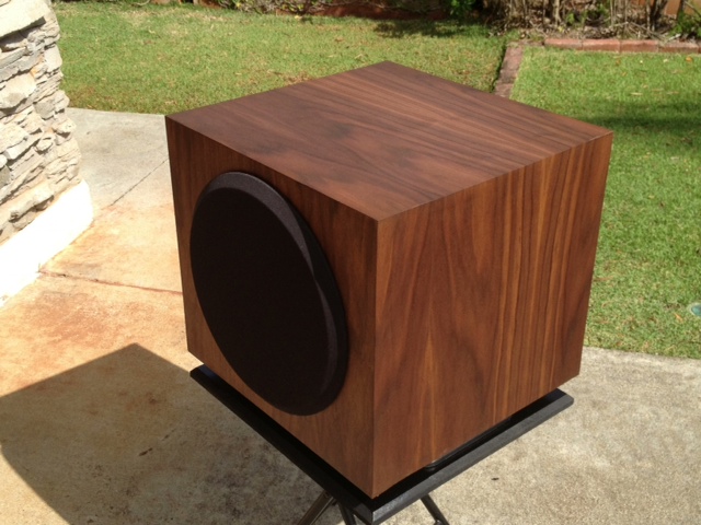

-
These are of the sub after final assembly... The fluorescent lighting makes the color look really drab...
Sorry but I did not have any pictures of the cabinet before veneering... Did not think about that... Doh!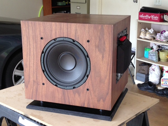

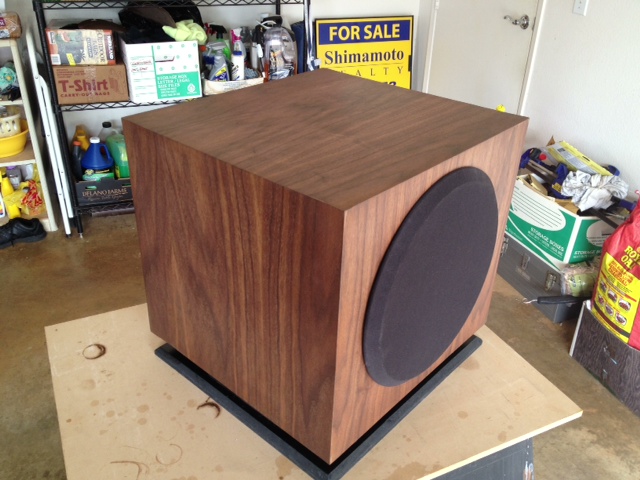
-
Very nice work! You underestimate your carpentry skills IMO...
-
Nice job!"He who fights with monsters should look to it that he himself does not become a monster. And when you gaze long into an abyss the abyss also gazes into you." Friedrich Nietzsche
-
Very nice work.Main Family Room: Sony 46 LCD, Sony Blue Ray, Sony DVD/VCR combo,Onkyo TXNR 708, Parasound 5250,
Polk SDS-SRS with mods, CSI 5 center + Klipsch SC2, Polk RT2000P rears, Klipsch KG 1.5's sides, Polk Micro Pro 1000, Polk Micro Pro 2000, Polk SW505, Belkin PF60, Signal Cable Classics,Monster IC's, 2 15 amp circuits & 1 20 amp circuit.
Living Room: Belkin PF60, Parasound HCA2200, MIT ProlineEXP balanced IC's,Emotiva XDA-1 DAC/Pre,Emotiva ERC2 transport,MIT AVT2, Polk LSI 9's. -
Nice job!
-
Nice job, and i must say, as an old landscaper/horticulturist, pretty nice turf also.humpty dumpty was pushed
-
Looks great!- Not Tom ::::::: Any system can play Diana Krall. Only the best can play Limp Bizkit.
-
Very nice looking!--Gary--
Onkyo Integra M504, Bottlehead Foreplay III, Denon SACD, Thiel CS2.3, NHT VT-2, VT-3 and Evolution T6, Infinity RSIIIa, SDA1C and a few dozen other speakers around the house I change in and out. -
I was contemplating using Polk's DB1040 drivers for this but they would not fit... The drivers were too deep and would hit the vent flared ends before seating... Another consideration was to make the rear plate removable, in case I have to replace the amp down the road. I would just have to cut out another 15" x 14.5" board and cut out the required size for the amplifier board.
Right now, I am listening to the sub as I write and it pumps out a lot of bass... I does not seem as tight as the original but it does move more air. -
Looks nice, if it sounds half and good as it looks your doing pretty good. haha.

-
Nice Job!Samsung UN55C6500 55" LED
Onkyo TX-NR3007
Polk Audio RT5000
-RT3000 front
-CS1000 center
-FX1000 dipole
Polk Audio PSW1000 5.1 sub
Polk Audio microPRO 4000 x2 5.2 subs:biggrin: -
Looks great!TV - LG 42" LED
Receiver - Pioneer VSX-521
Front speakers - Polk Monitor 40's Series II
Center - Polk Monitor CS1 Series II
Surround - Polk Audio OWM3
Subwoofer - JBL L8400P
"I was born with music inside me. Music was one of my parts. Like my ribs, my kidneys, my liver, my heart. Like my blood. It was a force already within me when I arrived on the scene. It was a necessity for me-like food or water."
~Ray Charles~ -
I applied Watco satin wax on it... It did not do anything to the finish... I then bought BriWax (a mixture of carnauba and beeswax) from Woodcraft. It left a nice satin finish on the veneer. It has to be left in a well ventilated area for a bit as the wax has an extremely strong petroleum odor (it has toulene) when applying.
I am considering building another subwoofer from scratch using two 12" drivers and a 500-watt amp... Unfortunately, if I used a vented box design, the cabinet will be pretty huge, about 22" each side, internally or about 24" externally using 1" MDF. Otherwise the frequency response will be pretty bad... -
Nice job, don't be hard on yourself, remember *most* people can't do what you just did.
-
Very nice to look at, I only wish I could have a listen! :sad:Family Room, Innuos Statement streamer (Roon Core) with Morrow Audio USB cable to McIntosh MC 2700 pre with DC2 Digital Audio Module; AQ Sky XLRs to CAT 600.2 dualmono amp, Morrow Elite Speaker Cables to NOLA Baby Grand Reference Gold 3 speakers. Power source for all components: Silver Circle Audio Pure Power One with dedicated 20 amp circuit to main panel.
Exercise Room, Innuos Streamer via Cat 6 cable connection to PS Audio PerfectWave MkII DAC w/Bridge II, AQ King Cobra RCAs to Perreaux PMF3150 amp (fully restored and upgraded by Jeffrey Jackson, Precision Audio Labs), Supra Rondo 4x2.5 Speaker Cables to SDA 1Cs (Vr3 Mods Xovers and other mods.), Dreadnaught with Supra Rondo 4x2.5 interconnect cables by Vr3 Mods. Power for each component from dedicated 20 amp circuit to main panel, except Innuos Statement powered from Silver Circle Audio Pure Power One. -
Here is something of interest... Below is a graph of the PSW650 response as graphed with Bass Box Pro...
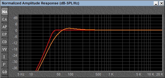
The orange line is the frequency response of the PSW650 in the original cabinet specifications. The red line is when the cabinet is optimized for the driver. The frequency response is a lot more linear if the cabinet was about 6.2 cubic feet or a 24" cube which is pretty massive. The -3dB point is 34.5Hz. The original design is down 3 dB at 50Hz. The optimal design uses two 4" ports 3.7" long.
So if someone wanted to really design a PSW650 with optimal parameters, the cabinet would be pretty massive. With a 250-watt amplifier, the output would be 117dB max for both designs.
If anyone is interested in the TS parameters, here they are...
Fs: 50.47 Hz
Qms: 6.04
Vas: 0.913 cu ft
Cms: 0.0245 in/lb
Mms: 2.506 oz
Rms: 8.222 lb/s
Dia: 8.435 in
sd: 55.88 sq in
Qes: 0.582
Re: 2.06 ohms
z: 2.472 ohms
BL: 2.007 lb/a
Pe: 250Watts
Qts: 0.531
1-w SPL: 89.5 dB
2.8V SPL: 95.44 db -
With a larger cabinet and lower extension you also have to worry about bottoming out the woofer."He who fights with monsters should look to it that he himself does not become a monster. And when you gaze long into an abyss the abyss also gazes into you." Friedrich Nietzsche
-
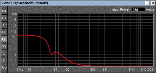
Yes... Unfortunately, there is no way of determining the xMax (maximum cone excursion) on the speaker. Looking at 250-watts input, the maximum excursion for the driver would be just under 11mm or .4207 inches. I doubt if anyone would really drive the sub to maximum power anyway so it should be safe as 11mm is rather a small number for xMax. Plus the xMax is at very low frequencies which the sub would never reach. For example, at 30Hz, the cone displacement is only 8mm or 1/4-inch at 250-watts input. At that point, the optimal curve is already down more than 6dB from flat.
-
sounds like you should start your own garage mod business.
-
I have redesigned the subs into an isobaric design. An isobaric design has the two drivers facing each other in a sealed chamber between them. One driver will be on the bottom of the vented cabinet facing down. The second driver will be facing up against the downward facing driver and the air chamber between the two must be airtight. The frequency response will be flat to 40Hz and will be -6dB @ 33.5Hz, exactly like the ideal graph shown above.
Advantage is that the cabinet size is down to a 16" cube, an isobaric design reduces bass distortion and if the drivers are right, the bass becomes tighter.. Disadvantage is that the output drops from 114dB to 111dB (there was an error earlier, it showed 500 watts amplification when it should only be 250... The actual size of the cabinet has to be increased a bit for the volume the amplifier will occupy, but it should not be more than an inch on one side. I will post specs later on and construction as it goes. -
Nice job on the build!
The -3dB point is 34.5Hz. The original design is down 3 dB at 50Hz. .
Fs: 50.47 Hz
Polk calls this a subwoofer?!?


