What effect would having the bias off have?
PreCd
Posts: 786
I have a GFA-555 that I have went through and replaced all caps, even the large filter caps. DC offset is very good sitting at 9mv per channel.
I would like to check the bias, have never done that, and was wondering what effect would it have on the sound if the bias were off?
I would like to check the bias, have never done that, and was wondering what effect would it have on the sound if the bias were off?
SDA2BTL
Marantz CD5004
Adcom GFA-545
Bottlehead Quickie Tube Preamp
Marantz CD5004
Adcom GFA-545
Bottlehead Quickie Tube Preamp
Post edited by PreCd on
Comments
-
http://en.wikipedia.org/wiki/Biasing
http://www.tnt-audio.com/clinica/bias_e.html
Couple of good readings to expand on it a bit.
Correct bias allows the transistors to operate in their intended "sweet spot". The short answer is amp that has extreme bias issues will have more distortion and it's most likely to be audible. It can also sound lean and closed in. Over bias can cause the transistors to saturate and again audible distortion and in extreme cases, especially with bi-polar transistors they can go into thermal runaway and eventually burn out.
I'm sure Fred will correct me if I'm wrong and hopefully he will add more info.
H9"Appreciation of audio is a completely subjective human experience. Measurements can provide a measure of insight, but are no substitute for human judgment. Why are we looking to reduce a subjective experience to objective criteria anyway? The subtleties of music and audio reproduction are for those who appreciate it. Differentiation by numbers is for those who do not".--Nelson Pass Pass Labs XA25 | EE Avant Pre | EE Mini Max Supreme DAC | MIT Shotgun S1 | Puritan Audio PSM136 Pwr Condtioner & Classic PC's | Legend L600 | Roon Nucleus 1 w/LPS - Tubes add soul! -
It keeps the transistors in their linear range, giving the best possible sound.
The amp can sound hazy, closed in, lean, compressed, etc if the bias is not set properly. It is a good idea to check it.
H9"Appreciation of audio is a completely subjective human experience. Measurements can provide a measure of insight, but are no substitute for human judgment. Why are we looking to reduce a subjective experience to objective criteria anyway? The subtleties of music and audio reproduction are for those who appreciate it. Differentiation by numbers is for those who do not".--Nelson Pass Pass Labs XA25 | EE Avant Pre | EE Mini Max Supreme DAC | MIT Shotgun S1 | Puritan Audio PSM136 Pwr Condtioner & Classic PC's | Legend L600 | Roon Nucleus 1 w/LPS - Tubes add soul! -
Since it's a push pull output stage crossover distortion will rear it's ugly head if bias is set less than optimum,likely giving it a hard / sterile flavour.If set too high while it may sound good will eventually lead to a failure of the output devices.I think I read in another thread that you have a service manual so it should indicate the proper level (measured in millivolts)and the correct test points at which to take the reading ie.such as across an emitter resistor.Be careful here as a slipped meter probe can cause a lot of grief in the form of blown unobtanium output tranasistors.I would like to check the bias, have never done that, and was wondering what effect would it have on the sound if the bias were off? -
Since it's a push pull output stage crossover distortion will rear it's ugly head if bias is set less than optimum,likely giving it a hard / sterile flavour.If set too high while it may sound good will eventually lead to a failure of the output devices.I think I read in another thread that you have a service manual so it should indicate the proper level (measured in millivolts)and the correct test points at which to take the reading ie.such as across an emitter resistor.Be careful here as a slipped meter probe can cause a lot of grief in the form of blown unobtanium output tranasistors.
I do have a service manual however it is not for my flavor of version 1 555 but a later version of the GFA-555 version 1. I am going to follow the warm up procedures in the manual but the designations are different in that manual from the board I have. Here is what I plan on doing, taking into consideration I follow the warmup/cool down procedures:
Place my VM on each side of the emitter resistor pictured below: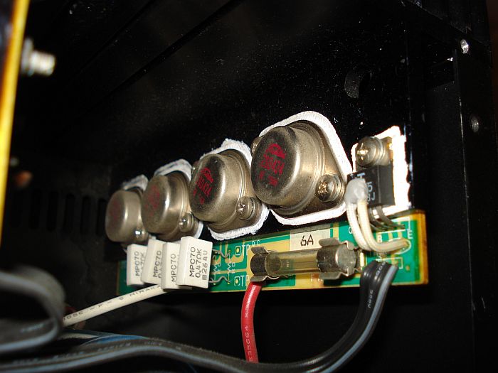
Then the adjustments will be made via the pots on each side of the board below allowing me to adjust for bias on the left and right channel.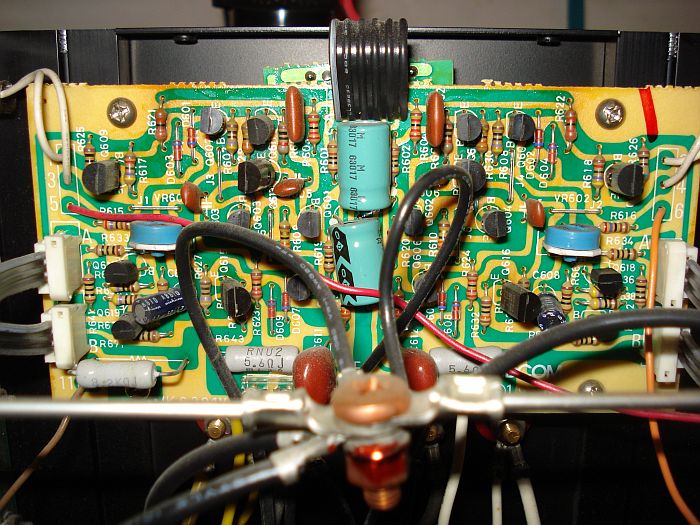
I will repeat this procedure for each channel following the warmup/cool down procedures in the manual. Sound about right?SDA2BTL
Marantz CD5004
Adcom GFA-545
Bottlehead Quickie Tube Preamp -
If you go over to DIYAUDIO.com there are several long, detailed threads on the 555. It should give you a step by step with proper bias voltage. The 555 II is biased quite a bit higher because it has larger heat sinks and different output configuration, so I wouldn't trust that value for the series I amps.
H9"Appreciation of audio is a completely subjective human experience. Measurements can provide a measure of insight, but are no substitute for human judgment. Why are we looking to reduce a subjective experience to objective criteria anyway? The subtleties of music and audio reproduction are for those who appreciate it. Differentiation by numbers is for those who do not".--Nelson Pass Pass Labs XA25 | EE Avant Pre | EE Mini Max Supreme DAC | MIT Shotgun S1 | Puritan Audio PSM136 Pwr Condtioner & Classic PC's | Legend L600 | Roon Nucleus 1 w/LPS - Tubes add soul! -
If you go over to DIYAUDIO.com there are several long, detailed threads on the 555. It should give you a step by step with proper bias voltage. The 555 II is biased quite a bit higher because it has larger heat sinks and different output configuration, so I wouldn't trust that value for the series I amps.
H9
I tell you it is a challenge to get where you want to go over there at DIYAudio. Great bunch but the threads get so long.
Thank you for your responses. The manual I have is for the GFA-555 Version 1 which is what I have but there are more than one flavor of that version 1. Just so happens I have the service manual for the other flavor which is not a great deal different but it is different. Here is the bias adjustment procedures for the GFA-555 Version 1 but a little different flavor than mine. I assume I can just run the amp a about 1/3rd volume to achieve the correct temp instead of the 66W into 8ohms: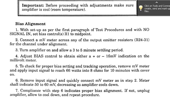 SDA2BTL
Marantz CD5004
Adcom GFA-545
Bottlehead Quickie Tube Preamp -
I got the amp all put together over the holidays. Changing those 26 year old filter capacitors significantly changed the sound. More musical. Less muddy. Greater detail.
The amp could use a bias checkup but I am having a terrible time finding documentation on adjusting it. I have a GFA-555 service manual but it contains the procedure for a PS board unlike mine. They may be similar enough that the procedure also pertains to it but I would like to run it by the forum. Hopefully some of the past Adcom techs will chime in or others who have the same board as mine.
Here is my board along with the link to the schematic:
Link to schematic: ftp://www.civilwarmedicalbooks.com/b...schematics.pdf
My GFA-555 PS board: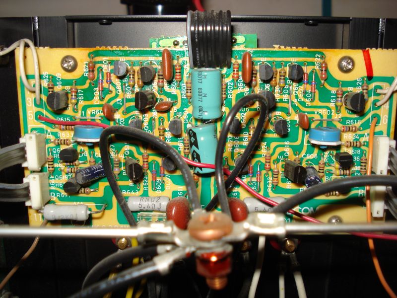
Here is the link to the only GFA-555 service manual I can find which has the bias alignment procedure in it. Remember the board in this manual differs from mine:
ftp://www.civilwarmedicalbooks.com/bias/Adcom_GFA-555_service_manual(1).pdf
Here is board the top link refers to: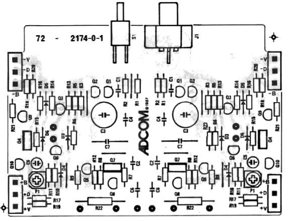 SDA2BTL
Marantz CD5004
Adcom GFA-545
Bottlehead Quickie Tube Preamp -
Got the links to the schematic and service manual screwed up in the previous post. Here are the corrected versions:
Here is my board along with the link to the schematic:
Link to schematic: www.civilwarmedicalbooks.com/bias/hfe_adcom_gfa-555_schematics.pdf
Here is the link to the only GFA-555 service manual I can find which has the bias alignment procedure in it. Remember the board in this manual differs from mine:
www.civilwarmedicalbooks.com/bias/Adcom_GFA-555_service_manual(1).pdfSDA2BTL
Marantz CD5004
Adcom GFA-545
Bottlehead Quickie Tube Preamp
