Monitor 11: Obsessing over foam placement
Options

motorcityguy
Posts: 70
I am working on my Monitor 11 speakers. These are the original version of the Monitor 11, with the 12" PR and the Sonex acoustic foam under the inboard mid-woofers. Mine are dated 1983.
I am in the process of replacing the old foam, and am obsessing over the correct size and position of the foam. I've searched the forum extensively, and found a surprising amount of pictures and info from other owners. With this post, I'm hoping to get confirmation that I'm on the right track, and (hopefully) document the adventure for future reference to others.
So, I understand that the acoustic foam goes “BELOW” the inboard driver, from the center support to the side of the cabinet. However, based on the size of my original foam pieces (6” x 7”) and location of glue residue, it’s clear that the foam does NOT extend all the way forward to the front baffle, or to the rear of the cabinet. Specifically, it is about 1” shy of the rear panel of cabinet, and ~2” shy of the front baffle. In other words, it doesn’t really extend further forward than the magnet itself.
As evidence, on both of my speakers, there is a magnet imprint on the forward face of the foam confirming it extends no further forward than the magnet. Thus, the foam is not fully “under” the inboard driver. Review of photos from original foam on other M11 speakers, verifies a similar gap at both front and rear of foam. Some examples show the foam LOWER than mine, such that the driver magnet is not contacting the foam. I suspect contacting the magnet is the result of production variation in the foam placement, which was likely done by hand.
In any case, these gaps strike me as odd, because I thought the idea of the foam was to “isolate” the sound waves of the inboard driver. As such, I would have expected foam to extend forward and under the open basket of the driver (i.e. to the front of the cabinet.)
Below is a sketch I made showing the location of my original foam, including the gaps at front and rear.
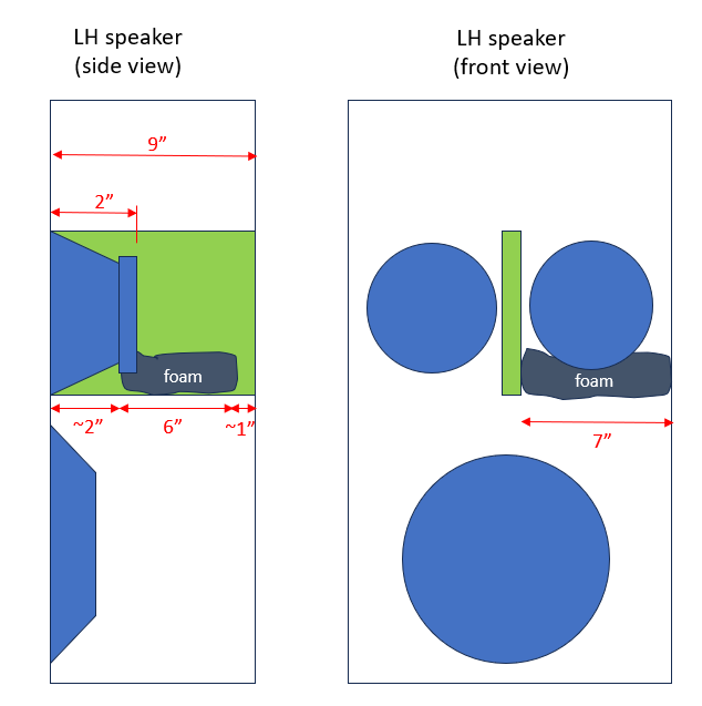
I am in the process of replacing the old foam, and am obsessing over the correct size and position of the foam. I've searched the forum extensively, and found a surprising amount of pictures and info from other owners. With this post, I'm hoping to get confirmation that I'm on the right track, and (hopefully) document the adventure for future reference to others.
So, I understand that the acoustic foam goes “BELOW” the inboard driver, from the center support to the side of the cabinet. However, based on the size of my original foam pieces (6” x 7”) and location of glue residue, it’s clear that the foam does NOT extend all the way forward to the front baffle, or to the rear of the cabinet. Specifically, it is about 1” shy of the rear panel of cabinet, and ~2” shy of the front baffle. In other words, it doesn’t really extend further forward than the magnet itself.
As evidence, on both of my speakers, there is a magnet imprint on the forward face of the foam confirming it extends no further forward than the magnet. Thus, the foam is not fully “under” the inboard driver. Review of photos from original foam on other M11 speakers, verifies a similar gap at both front and rear of foam. Some examples show the foam LOWER than mine, such that the driver magnet is not contacting the foam. I suspect contacting the magnet is the result of production variation in the foam placement, which was likely done by hand.
In any case, these gaps strike me as odd, because I thought the idea of the foam was to “isolate” the sound waves of the inboard driver. As such, I would have expected foam to extend forward and under the open basket of the driver (i.e. to the front of the cabinet.)
Below is a sketch I made showing the location of my original foam, including the gaps at front and rear.
Comments
-
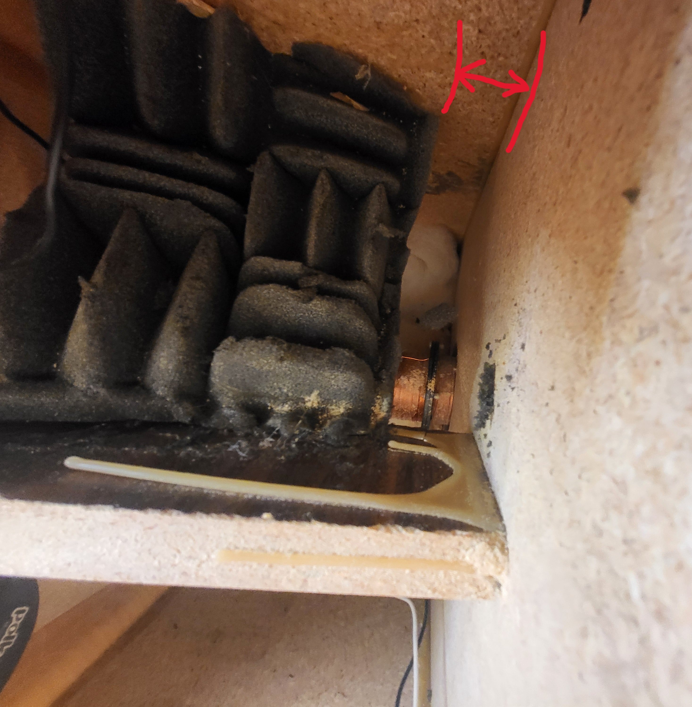
Here are some photos illustrating my observations.
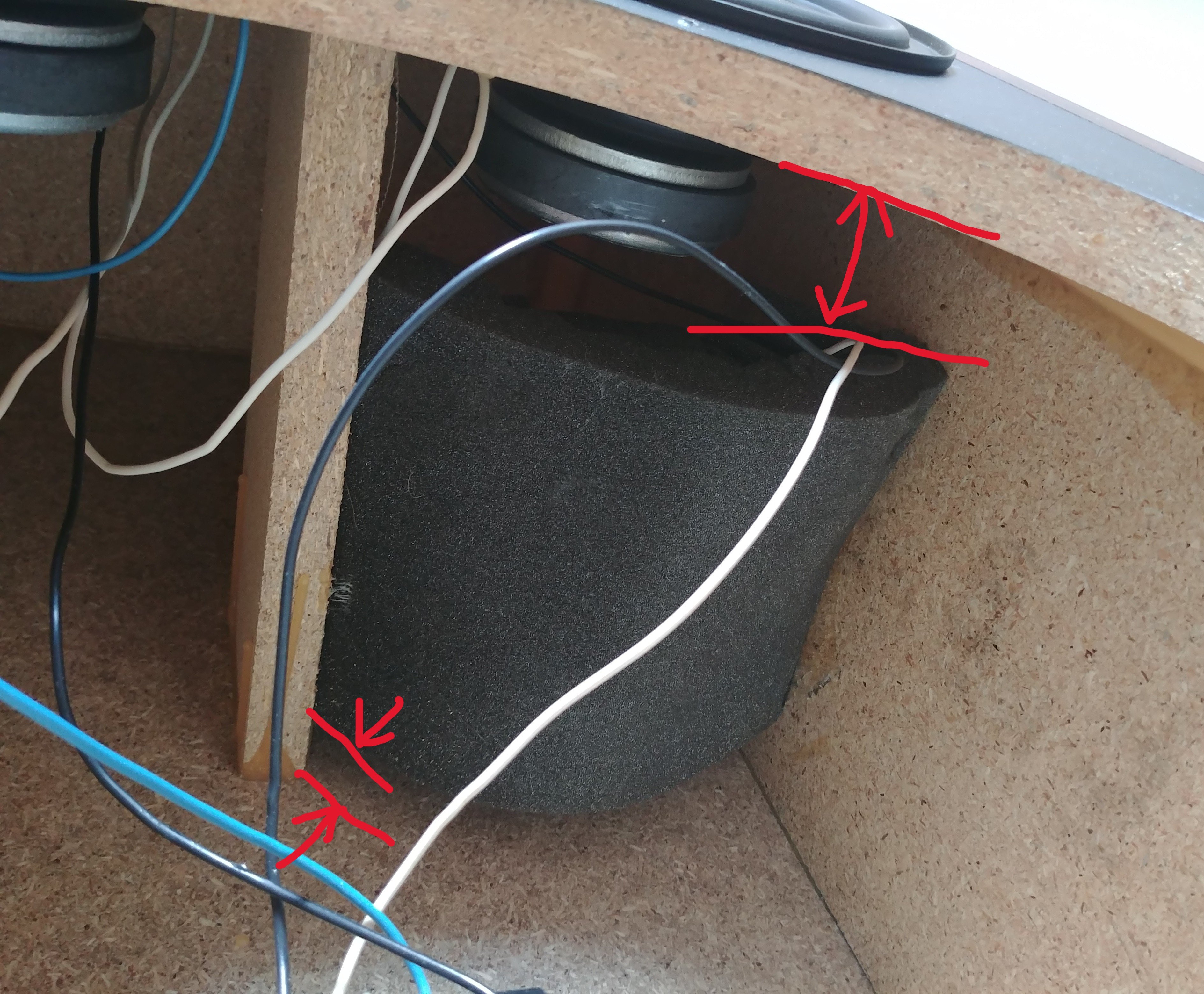
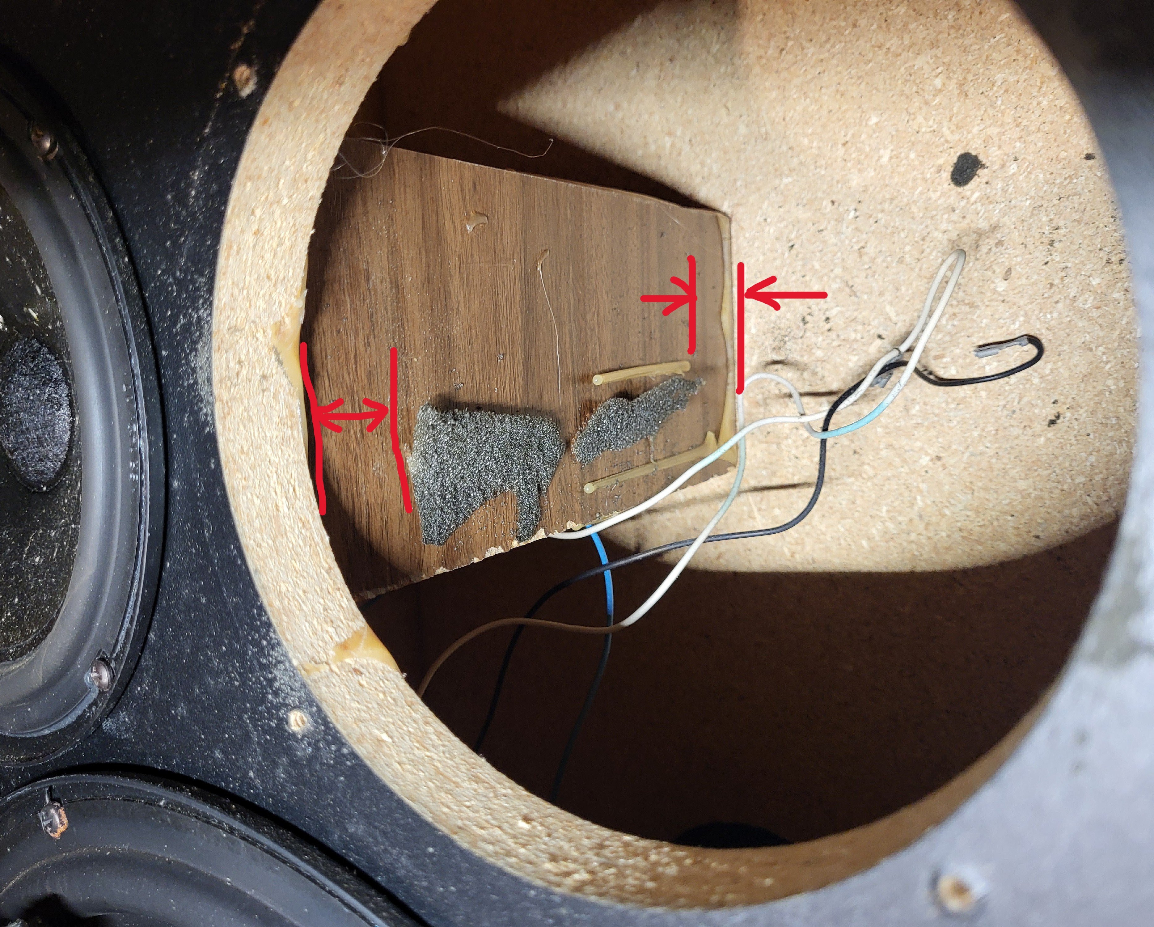
First pic shows front view of the intact original foam on my RH speaker. Notice the gap to the front baffle, as well as a magnet imprint, that shows approximate position of front edge of foam. The magnet imprint identifies the front gap as ~2” back from inside of baffle, which was confirmed by measurement.
Second pic is of same speaker, showing the gap to the rear panel, which I measured at approximately 1”.
Third pic is from another member, showing a view from below, of their original foam. Notice the gap is about twice as large at front of foam, as it is at the back. Note also, that this foam is slightly lower than mine and thus has no interference with the magnet.
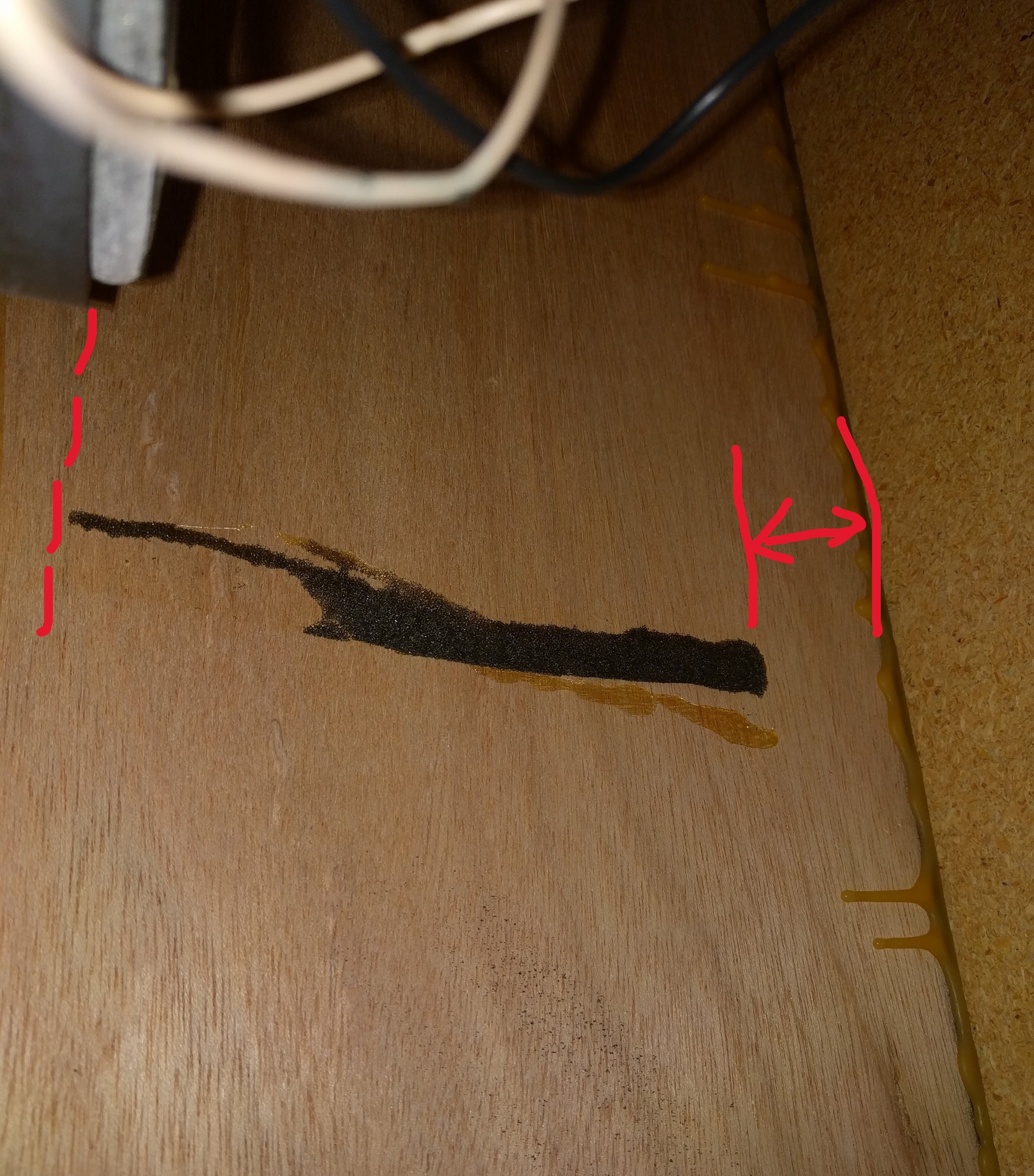
Fourth pic is the foam’s glue residue in my LH speaker. Again, notice the apparent end of both the foam and the glue, indicating a gap at the front and rear of the foam. The front gap is about twice the width of the rear gap.
Fifth pic is foam glue residue from another member’s M11. This also shows similar gaps at front and rear of foam. Note that the front edge of the foam is approximately in line with the rear edge of the driver magnet.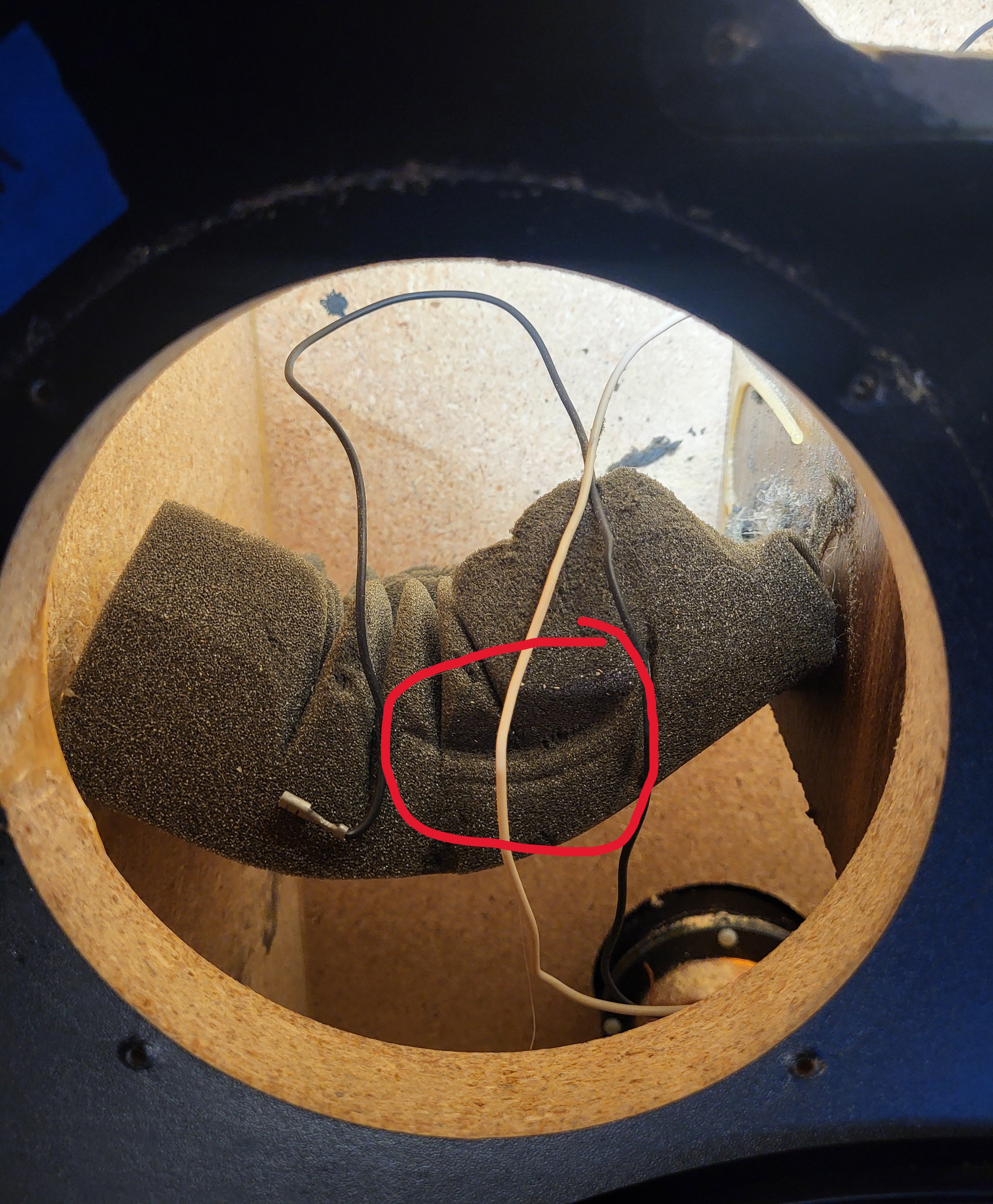
-
I seem to recall the foam in my father's covered the entire space, but it's been so many years my memory could be off.
Political Correctness'.........defined
"A doctrine fostered by a delusional, illogical minority and rabidly promoted by an unscrupulous mainstream media, which holds forth the proposition that it is entirely possible to pick up a t-u-r-d by the clean end."
President of Club Polk -
I would think that there need to be a bit of space between the foam and cabinet to allow enough back pressure for the passive to work correctly. It doesn't take much foam to dampen the driver a bit but not so much to leave the passive dependent on just one of the two drivers in the cabinet.
I'm probably way off and talking out of my rear end, that's my take anyways.
😜 -
Yeah I think the space at the baffle is definitely to not interfere with the passive radiator interaction and the foam is to help with dampening a standing wave on the vertical dimension of the speaker enclosure. Is it pretty much centered on the vertical internal dimension? The standing wave is probably at a frequency that only affects the sound of the midrange driver and therefore no need for foam on the other side.George / NJ
Polk 7B main speakers, std. mods+ (1979, orig owner)
Martin Logan Dynamo sub w/6ft 14awg Power Cord
Onkyo A-8017 integrated
Logitech Squeezebox Touch Streamer w/EDO applet
iFi nano iDSD DAC
iPurifier3
iDefender w/ iPower PS
Custom Steve Wilson 1m UPOCC Interconnect
iFi Mercury 0.5m OFHC continuous cast copper USB cable
Custom Ribbon Speaker Cables, 5ft long, 4N Copper, 14awg, ultra low inductance
Custom Vibration Isolation Speaker Stands and Sub Platform -
It's to reduce the sound waves reaching the PR in order to reduce the bass output as they are bass heavy speakers already.Political Correctness'.........defined
"A doctrine fostered by a delusional, illogical minority and rabidly promoted by an unscrupulous mainstream media, which holds forth the proposition that it is entirely possible to pick up a t-u-r-d by the clean end."
President of Club Polk -
I seem to recall the foam in my father's covered the entire space, but it's been so many years my memory could be off.
Couldn't have been memory foam then.Don't take experimental gene therapies from known eugenicists. -
I think this foam could do multiple things, suppress the base response from being too strong and suppress a standing wave. Maybe Polk played with the size of the foam and either went from full blockage to a reduced size or vice versa.George / NJ
Polk 7B main speakers, std. mods+ (1979, orig owner)
Martin Logan Dynamo sub w/6ft 14awg Power Cord
Onkyo A-8017 integrated
Logitech Squeezebox Touch Streamer w/EDO applet
iFi nano iDSD DAC
iPurifier3
iDefender w/ iPower PS
Custom Steve Wilson 1m UPOCC Interconnect
iFi Mercury 0.5m OFHC continuous cast copper USB cable
Custom Ribbon Speaker Cables, 5ft long, 4N Copper, 14awg, ultra low inductance
Custom Vibration Isolation Speaker Stands and Sub Platform -
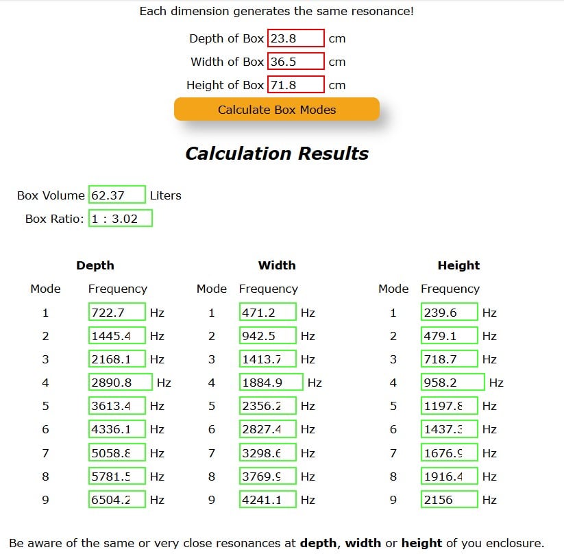
Ignoring the partition and assuming a 2 in. tall toe kick and 3/4" particle board, this would be the standing wave modes:
George / NJ
Polk 7B main speakers, std. mods+ (1979, orig owner)
Martin Logan Dynamo sub w/6ft 14awg Power Cord
Onkyo A-8017 integrated
Logitech Squeezebox Touch Streamer w/EDO applet
iFi nano iDSD DAC
iPurifier3
iDefender w/ iPower PS
Custom Steve Wilson 1m UPOCC Interconnect
iFi Mercury 0.5m OFHC continuous cast copper USB cable
Custom Ribbon Speaker Cables, 5ft long, 4N Copper, 14awg, ultra low inductance
Custom Vibration Isolation Speaker Stands and Sub Platform -
Thanks, all, for the input. Just to be safe, I'm thinking I'll just replicate the original foam size and location (albeit a tad "lower" so the MW magnet is no longer smashing into the foam).Gardenstater wrote: »Is it pretty much centered on the vertical internal dimension?
That's a good question. I didn't measure the vertical height of the foam, relative to the internal cabinet dimension. I'm not at my storage location so I can't measure mine, but "visually" this picture (not mine) suggests the foam is close to mid-cabinet but maybe slightly higher than than mid-point.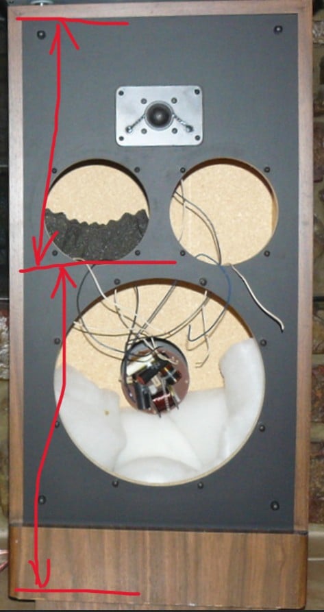
-
Attach the foam using 2-piece adhesive velcro so you can adjust location if needed.
-
It looks like open cell and clearly has the one side sawtoothed. How thick is the foam......about 2 in.? Any idea on the density in lb/ cu. ft?George / NJ
Polk 7B main speakers, std. mods+ (1979, orig owner)
Martin Logan Dynamo sub w/6ft 14awg Power Cord
Onkyo A-8017 integrated
Logitech Squeezebox Touch Streamer w/EDO applet
iFi nano iDSD DAC
iPurifier3
iDefender w/ iPower PS
Custom Steve Wilson 1m UPOCC Interconnect
iFi Mercury 0.5m OFHC continuous cast copper USB cable
Custom Ribbon Speaker Cables, 5ft long, 4N Copper, 14awg, ultra low inductance
Custom Vibration Isolation Speaker Stands and Sub Platform -
slow_polk7 wrote: »Attach the foam using 2-piece adhesive velcro so you can adjust location if needed.
And that will also let you remove it and hear the difference. I’m betting that at around 60 Hz (wavelength ~19 ft) that 2–3″ thick foam won’t have much impact on passive radiator output at all. What you should hear is clearer midrange — vocals especially — with the foam installed.
Cool little experiment: play a pure 60 Hz test tone and compare the inner midwoofer’s excursion with the foam in place versus removed. If the foam were really isolating that driver from the PR, you’d expect to see a bit more excursion on the inner driver with the foam installed (less acoustic loading). I’m betting you won’t see any meaningful difference between the two conditions. The outer driver can serve as a handy control.George / NJ
Polk 7B main speakers, std. mods+ (1979, orig owner)
Martin Logan Dynamo sub w/6ft 14awg Power Cord
Onkyo A-8017 integrated
Logitech Squeezebox Touch Streamer w/EDO applet
iFi nano iDSD DAC
iPurifier3
iDefender w/ iPower PS
Custom Steve Wilson 1m UPOCC Interconnect
iFi Mercury 0.5m OFHC continuous cast copper USB cable
Custom Ribbon Speaker Cables, 5ft long, 4N Copper, 14awg, ultra low inductance
Custom Vibration Isolation Speaker Stands and Sub Platform -
Gardenstater wrote: »slow_polk7 wrote: »Attach the foam using 2-piece adhesive velcro so you can adjust location if needed.
And that will also let you remove it and hear the difference. I’m betting that at around 60 Hz (wavelength ~19 ft) that 2–3″ thick foam won’t have much impact on passive radiator output at all. What you should hear is clearer midrange — vocals especially — with the foam installed.
Cool little experiment: play a pure 60 Hz test tone and compare the inner midwoofer’s excursion with the foam in place versus removed. If the foam were really isolating that driver from the PR, you’d expect to see a bit more excursion on the inner driver with the foam installed (less acoustic loading). I’m betting you won’t see any meaningful difference between the two conditions. The outer driver can serve as a handy control.
One thing I'm 110% about, is the CRS+ driver suspended foam mod I've done twice now, DOES NOT affect bass response, only cleans up the midrange backwaves.Don't take experimental gene therapies from known eugenicists. -
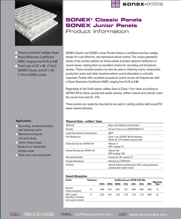
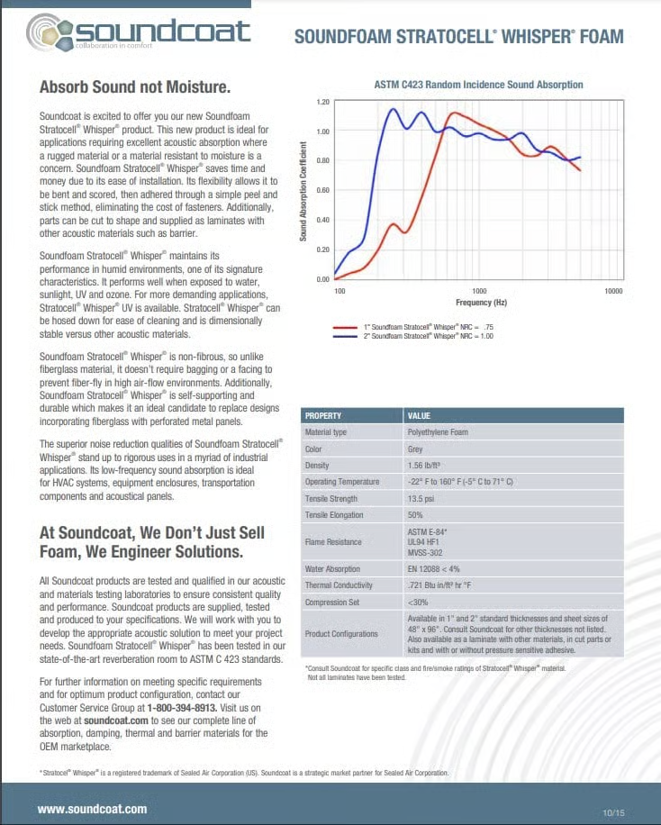
You can see from the data below that the absorption coefficient for open cell acoustical foam 2 in. thick is 0.05 at 125 Hz. for the Sonex open cell melamine which is less dense, and about 0.05 at 100 Hz for the Soundcoat Stratocell Polyurethane, which is denser than the Sonex. That's where the material is mounted on a plywood backing and the sound passes through twice. In this case the sound only passes through once in going from the driver to the passive so the transmissibility loss from absorption is maybe half. Also only 2/3 of the cross sectional area in the speaker has the foam.
George / NJ
Polk 7B main speakers, std. mods+ (1979, orig owner)
Martin Logan Dynamo sub w/6ft 14awg Power Cord
Onkyo A-8017 integrated
Logitech Squeezebox Touch Streamer w/EDO applet
iFi nano iDSD DAC
iPurifier3
iDefender w/ iPower PS
Custom Steve Wilson 1m UPOCC Interconnect
iFi Mercury 0.5m OFHC continuous cast copper USB cable
Custom Ribbon Speaker Cables, 5ft long, 4N Copper, 14awg, ultra low inductance
Custom Vibration Isolation Speaker Stands and Sub Platform -
I'd lean towards Gardenstater's math here, though lower frequencies coming from the bass driver are going to cut through the foam regardless, it may dampen a little going up to the midrange with it's standing frequencies but even then, those frequencies should have no trouble exiting the enclosure and the back reflections would be minimally perceived if at all. Back in the 80s and before, designs assumed that foam did help a lot more than they actually do, it wouldn't hurt to add it to the enclosure as described but given what we know how about how sound travels, you'll have more optimization spending sometime with speaker placement and adjusting the room acoustics in your listening area than you would adding foam to the interior of the speaker. Isolation/dampening of the drivers would require dense materials to help reject external frequencies from conflicting from other drivers but then you would want to run the math to figure out the foam to place within those areas to help which might end up being more work than it's worth IMO.
Furthermore, those OG drivers extend down to 19hz iirc. Going up to around 250hz, those waves are so long that it will still cut through foam composites, even ranging up to 500hz to be honest. In past studio treatments I've done, we found that building bass traps was more effective for the room to help with nodes and anti-nodes but you can't really build a bass trap inside a speaker. It just goes back to treating the room and speaker placement ultimately.
It would be worth trying that experiment posed above to see if your ears can hear any meaningful difference, even when my ears were at their prime in my late teens/early twenties, I could barely hear differences in the enclosures themselves and the room treatments did a whole lot more. Of course, due to psychoacoustic phenomenon, YMMV so it's always worth just trusting what you hear yourself and going off of that. I often find the experimentation to be a good bit of fun anyways.
-
That info came from Matt Polk.It's to reduce the sound waves reaching the PR in order to reduce the bass output as they are bass heavy speakers already.Political Correctness'.........defined
"A doctrine fostered by a delusional, illogical minority and rabidly promoted by an unscrupulous mainstream media, which holds forth the proposition that it is entirely possible to pick up a t-u-r-d by the clean end."
President of Club Polk -
I wouldn't doubt that it would attenuate the upper bass and lower midrange noticeably (maybe subtle though) to the ear, even with only 2/3 of the midrange side of the speaker's cross sectional area spanned. Also, in his diagram and photo you can see that they didn't even put the foam under the downward facing basket window with part of it even behind the magnet. I wouldn't doubt that they were fiddling with the opening sizes and the foam locations over the run of the speaker.
There is a 250 Hz standing wave in the vertical direction that may have been annoying and it would affect a lot of important instruments and even male vocals, but that's the lowest freq. standing wave and the other ones would be more effectively taken out by the foam.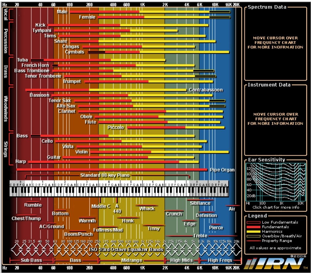
George / NJ
Polk 7B main speakers, std. mods+ (1979, orig owner)
Martin Logan Dynamo sub w/6ft 14awg Power Cord
Onkyo A-8017 integrated
Logitech Squeezebox Touch Streamer w/EDO applet
iFi nano iDSD DAC
iPurifier3
iDefender w/ iPower PS
Custom Steve Wilson 1m UPOCC Interconnect
iFi Mercury 0.5m OFHC continuous cast copper USB cable
Custom Ribbon Speaker Cables, 5ft long, 4N Copper, 14awg, ultra low inductance
Custom Vibration Isolation Speaker Stands and Sub Platform -
That info came from Matt Polk.It's to reduce the sound waves reaching the PR in order to reduce the bass output as they are bass heavy speakers already.
Don't take experimental gene therapies from known eugenicists. -

George / NJ
Polk 7B main speakers, std. mods+ (1979, orig owner)
Martin Logan Dynamo sub w/6ft 14awg Power Cord
Onkyo A-8017 integrated
Logitech Squeezebox Touch Streamer w/EDO applet
iFi nano iDSD DAC
iPurifier3
iDefender w/ iPower PS
Custom Steve Wilson 1m UPOCC Interconnect
iFi Mercury 0.5m OFHC continuous cast copper USB cable
Custom Ribbon Speaker Cables, 5ft long, 4N Copper, 14awg, ultra low inductance
Custom Vibration Isolation Speaker Stands and Sub Platform -
Gardenstater wrote: »It looks like open cell and clearly has the one side sawtoothed. How thick is the foam......about 2 in.? Any idea on the density in lb/ cu. ft?
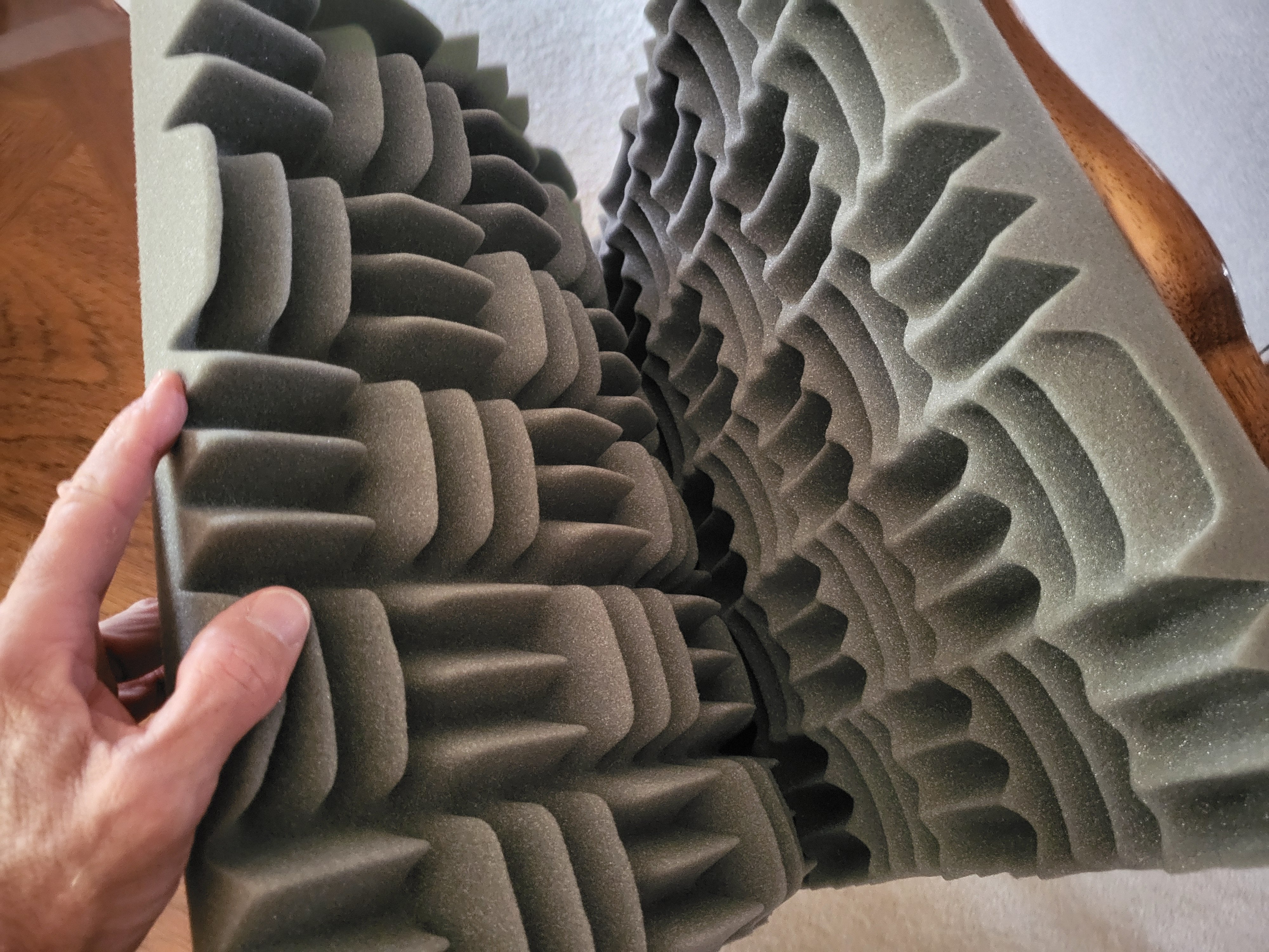
The replacement foam I have sourced is "Sonex Classic," a longtime product, and one of their most popular. It uses Willtec (brand) melamine foam. As near as I can tell, it's identical in thickness and pattern to the original foam, so I suspect it's what Polk used.
As to the actual thickness, I measured both the original and new foam to be about 3.5". However, note that Sonex advertises this as "2-inch" because apparently they go by the thickness of the uncontoured part of the foam.
Here's a picture of the new foam, prior to cutting and installing.